+86 13638632902
 Jason@cleanroomequips.com


 MENU
MENU
Getting process cooling water specifICations right is critical for Semiconductor, electronICs, and cleanroom facilities. This guide by the Deiiang™ team, led by Jason Peng, offers sample data, design formulas, and ready-to-use specification clauses for your process cooling water system procurement.
What Is a Process Cooling Water (PCW) System?
Process cooling water systems are used to cool manufacturing equipment such as tools, air compressors and precision plant equipment by circulating a temperature controlled water stream. The system requires a tightly controlled temperature and high quality water. Proper PCW specifications define supply temperature (often 15–22°C), pressure, and material Requirements to ensure production uptime.
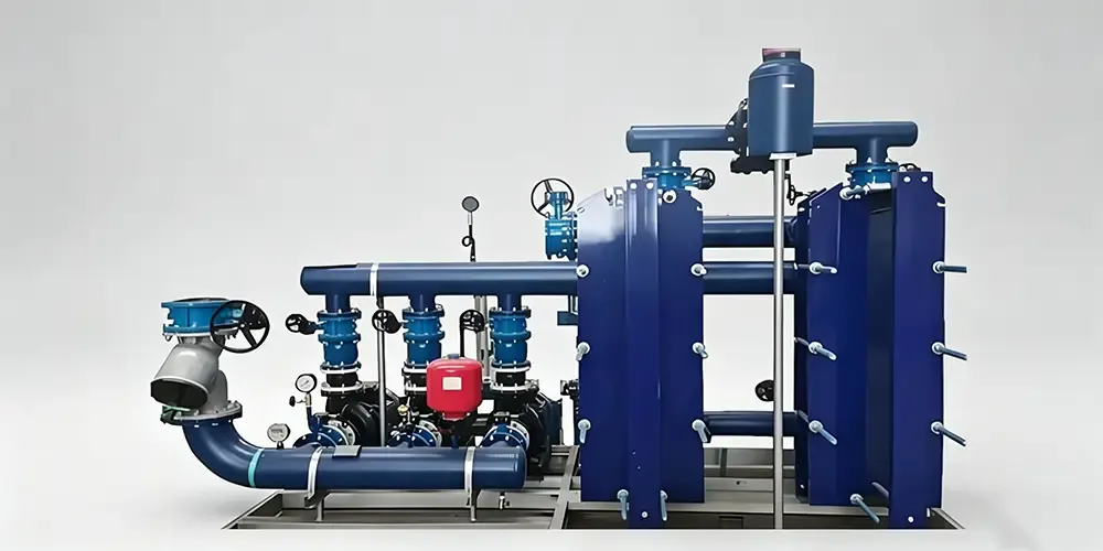
Key Insight: A typical Process Cooling Water system is designed to be a standalone system that is typically separated from the chiller plant by a plate heat exchanger. This allows for the best protection of tools and the ability to maintain independent water chemistry.
Typical PCW System Configuration (With Deiiang Sample Data)
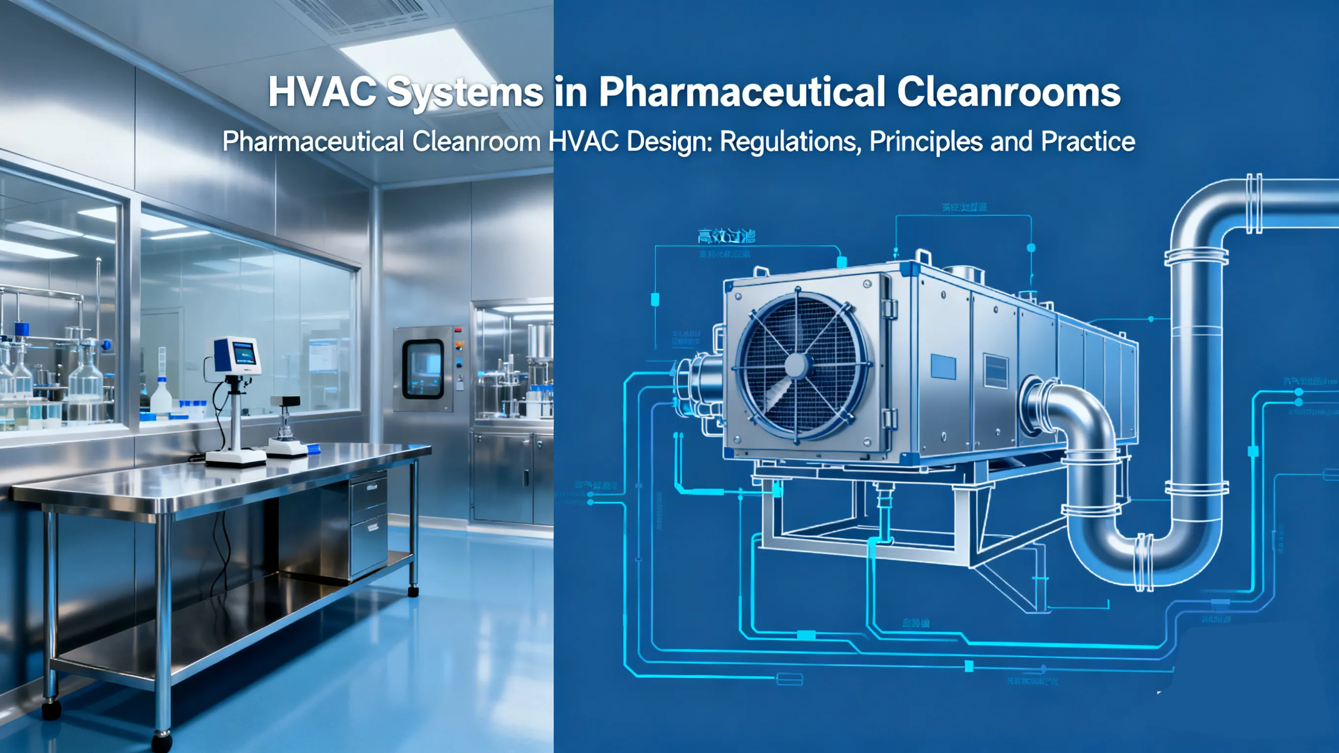
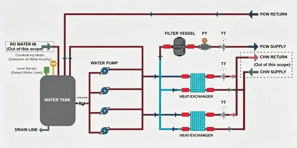
A typical process cooling water system is composed of a number of major components including a plate heat exchanger, a SS304 storage tank, VFD pumps, bag filters and automatic dosing equipment. The following are two typical process cooling water system specifications from past Deiiang™ projects which have been properly scaled to meet the design requirements for eACH job.
EodxiQ7HaQI
Deiiang Standard PCW Module – Sample Specification
The main loop provides 2,500 kW of cooling to an Electronics cleanroom operating between 15°C and 22°C with N+1 pumps for redundancy.
| Parameter | Specification |
|---|---|
| Supply Temperature | 15–22 ℃ |
| Cooling Capacity | 2,500 kW |
| Flow Rate | 300 m³/h |
| Supply Pressure | 0.8 MPa |
| Heat Exchanger | SS304 Plate, ΔP ≤ 5 m |
| Tank | 5.0×4.0×3.0 m, SS304, 50mm insulation |
| Pumps | 4×100 m³/h @ 80 m, 55 kW (3 duty+1 standby) |
| Bag Filter | 300 m³/h, 50 μm, SS304 |
| Water Treatment | Auto dosing + conductivity blowdown |
Supply Temp.15–22℃
Capacity2,500 kW
Flow300 m³/h
Pressure0.8 MPa
Heat ExchangerSS304, ΔP≤5m
Tank5×4×3m, SS304
Pumps4×100m³/h, 80m
Filter300m³/h, 50μm
Additional PCW Loop for Air Compressors
A dedicated 350 kW loop serves air compressors, decoupled to avoid disturbing the main process loop.
| Parameter | Specification |
|---|---|
| Cooling Capacity | 350 kW |
| Flow Rate | 60 m³/h |
| Supply Pressure | 0.4 MPa |
| Heat Exchanger | SS304 Plate |
| Pumps | 2×60 m³/h @ 40 m, 11 kW (1+1) |
| Bag Filter | 55 m³/h, 50 μm, SS304 |
Capacity350 kW
Flow60 m³/h
Pressure0.4 MPa
Pumps2×60m³/h, 40m
Filter55m³/h, 50μm
Key Technical Parameters for PCW Specifications
Every PCW specification must address thermal and hydraulic design. Use the formula Q = m × Cp × ΔT : for 2,500 kW and ΔT=7°C, the required flow is about 307 m³/h, matching the sample 300 m³/h with a safety margin.
Thermal Design Parameters
Supply/Return: 15°C / 22°C (Electronics), 7°C/12°C chilled water side.
Cooling capacity: Include 10–15% safety factor above total tool load.
Temperature fluctuation: ±0.5°C for sensitive tools.
Hydraulic Design Parameters
Flow rates: 300 m³/h (main), 60 m³/h (compressor).
Pump head: 80 m for 0.8 MPa delivery; 40 m for 0.4 MPa.
Redundancy: N+1 (3 duty+1 standby / 1+1).
Pressure rating: 1.0 MPa, with heat exchanger ΔP ≤ 5 m.
materials & Water Quality
Wetted parts: Wetted components of contact with cooling water are made of SS304 for the tank, heat exchanger, filter cases and pump cases.
Tank insulation:50mm elastomeric foam + 0.5mm aluminum cladding.
Water quality: Conductivity<100 μS/cm, is controlled by automatic blowdown and softened makeup water.
Control & Instrumentation
VFD control: VFD is controlled by differential pressure (ΔP) between supply and return headers.
Monitoring: Supply/return temperature, ΔP, pump status, faults, return water conductivity.
Panel: External E-Stop, properly earthed, dual power auto transfer switch.
Sample PCW Technical Requirement Template (Ready-to-Use)
Copy these process cooling water specifications directly into your RFQ. They reflect Deiiang™ field experience and reduce post-award change orders.
General Scope
The integrated PCW package will consist of Plate Heat Exchangers, SS304 storage tank, VFD driven pumps, Bag Filters, necessary valves, instruments etc along with control panel for complete package. It will be pre-piped and pre-tested.
Factory-assembled skid with interconnecting piping and wiring.Control panel equipped with VFDs for pumps, PLC/HMI for process control and field I/O terminals.FAT documentation and on-site commissioning support.
Equipment Requirements (Example Items)
Plate heat exchanger: SS304, 2,500 kW, 300 m³/h, ΔP ≤5 m.
PCW tank: 5.0×4.0×3.0 m, SS304, 3mm wall, 50mm insulation.
VFD pumps: 4×100 m³/h @ 80 m, 55 kW, with soft connections and vibration isolation.
Bag filter: 300 m³/h, 50 μm, SS304 housing.
Dosing system: Indoor, 1.0 MPa, 220V/50Hz, ~200W.
Quality & Standards
Manufacturing under ISO 9001. Welders certified. Hydrostatic test at 0.8 MPa for 2 hours, zero leakage. Pipeline flushing before commissioning.
Control Strategy & Automation for PCW Systems
The process cooling water system uses ΔP-based VFD pump control. As demand drops, pump speed reduces, saving 40–60% energy (affinity laws: P₂/P₁ = (N₂/N₁)³). A conductivity controller opens a blowdown valve when levels exceed ~100 μS/cm, while the dosing system injects chemicals proportionally.
Deiiang Project Case Studies
Deiiang™ and Jason Peng have deployed these PCW specifications in real facilities. Two examples follow.
Electronics Cleanroom Main Loop (2,500 kW)
Challenge: A 24/7 cleanroom needed stable cooling for multiple tools with fluctuating demand. Solution: ΔP-controlled VFD pumps (3+1) maintained pressure within ±2%; prefabricated skid cut installation time by 40%. The SS304 tank and automatic dosing kept conductivity below 80 μS/cm.

Persona: Li, Facility Manager
PERSONA
Facility manager Li from an electronics plant wanted reliable process cooling water specs for a tender. He can rely on the Template from Section 4 plus the respective case studies as he e.g. specifies SS304 materials, N+1 pumps plus conductivity control without any risk of future downtime.
Installation, Commissioning and After-Sales Requirements
Send all PCW drawings to client for approval before fabrication.
On-site commissioning by experienced engineers until system meets specs.
12-month warranty with free parts; pre-expiry inspection and report.
24h phone support, 2h response, on-site 24/7 service for critical issues.
One week of on-site operator training.
How to Use This Specification in Your Own PCW Projects
Adapt these process cooling water specifications in five steps:
Copy template clauses from Section 4 of the document and reduce down to your specific project scale.
Re-calculate the flow and head based off the actual loads for Section 3 testing as well.
Add Pharmaceutical or semiconductor-specific cleanliness requirements if needed.
Include the hydrostatic test and flushing clauses universally.
Share the guide with your mechanical and controls teams.
Pro Tip from Jason Peng: "When designing pumps always account for the pressure drop of the heat exchanger (3–5m), the filters (1–3m) and the piping friction before applying a safety factor. A 10m shortage in head will not translate into sufficient flow for a pump designed for that condition.."
Micro-Glossary – Key PCW Terms Explained
TERM
Process Cooling Water (PCW): A closed loop system that is isolated from the rest of the plant by a heat exchanger. It supplies a constant temperature of water to the process tools.
TERM
Plate Heat Exchanger (PHE): A compact unit made of SS304 which transfers heat from PCW to chilled water without mixing of the two fluids.
TERM
VFD Pump: A centrifugal pump that is equipped with a variable speed drive. The VFD allows the pump to run at the exact speed to maintain a constant ΔP.
TERM
Conductivity Control: On-line conductivity analyser continuously monitors the concentration of dissolved solids in solution and triggers a blowdown and/or makeup as required.
TERM
SS304 Combination Tank: This is a SS304, modular, combination of a tank and thermal buffer and chemical injection point.
References
ISO 9001:2015 — Quality Management Systems. View: https://www.iso.org/standard/62085.html
ASME B31.3 — Process Piping. View: https://www.asme.org/codes-standards/find-codes-standards/b31-3-process-piping
ASHRAE Handbook — Water Treatment. View: https://www.ashrae.org/technical-resources/ashrae-handbook
SEMI S2 — Semiconductor Equipment Safety. View: https://www.semi.org/en/standards