+86 13638632902
 Jason@cleanroomequips.com


 MENU
MENU
In high-tech manufacturing processes it is necessary to keep the working environment in ultra-clean condition and use fan-powered filter module to achieve this goal. Deiiang™ ffu are made of galvanized enclosure and equipped with AC motor to provide stable average wind speed of 0.3-0.5m/s. This technical FFU guide to FFU goes into the details of fan filter unit, their roles in cleanrooms, advantages, airflow distribution, installation methods, and also introduces into the customized ffu solutions provided by Deiiang™.
In order to provide the best solutions to customers, each installation of Fan filter unit must balance several factors including filtration efficiency, electricity consumption and available space. According to Jason Peng, product designer of Deiiang™, the current FFU on the market can reach 99.99%@0.3μm efficiency with the initial pressure loss of 110Pa@0.45m/s, which is the industry benchmark for FFU.
What is an FFU?
FFU (Fan Filter Unit) are motorized ceiling mounted air supply units that can supply clean air to micro-environments. Each clean air delivery unit contains a fan and terminal HEPA filter. Air is drawn into the fan-powered filter module from the ambient and forced through the media. Deiiang FFU models offer standard air flow rates from 500m³/h to 2,000m³/h using 99.99%@0.3μm efficient filters. Our FFU’s are used in a wide variety of environments including pharmaceuticals and semiconductor fabrication.
Deiiang Fan filter unit Core Specs • Air volume range: 500m³/h – 2,000m³/h • Various form factors • 99.99%@0.3μm HEPA filter media • Initial pressure loss: 110Pa@0.45m/s
FFU’s enable to dispense with HVAC-based ductwork systems, because the Fan filter unit operates as a self-contained air cleaning unit as a “micro-environmental air cleaning module”. Because there is no need for large HVAC systems and corresponding risk of failure, single fan-powered filter module failures do not put the entire cleanroom at risk. Additional FFUs are simply mounted into the air distribution grid as needed to meet the required cleanroom classification as required.
New generation clean air delivery units from Deiiang™ for example are designed for easy filter replacement (tool-free) and for hot-swapping of the Fan filter unit motor. This results in reduced maintenance downtime of up to 60% as compared to first generation air handling FFU’s.
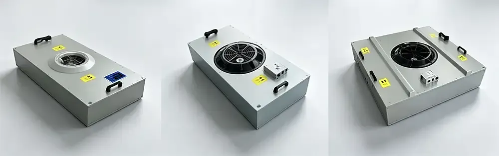
Deiiang™ FFU technical documentation and selection tools
The FFU's Role in Cleanrooms
FFUs are typically used to localize air cleaning in rooms. By providing individual workstations with air cleaning, fan-powered filter module allow for redundant contamination control as well as targeted cleaning. FFUs generate an external static pressure of approximately 190Pa (10mmAq) which is greater than the downward airflow can withstand when it meets with any form of resistance. As a result, clean air is continually directed down towards the floor of the room and washed down over the work surface to pick up any airborne contaminants. When used in semiconductor installations for photolithography, Deiiang™’s FFU’s are specifically designed and configured to keep FFU fan vibration coefficients at ultra-low values of 0.2–0.5. These critical vibration values are measured using laser interferometry as part of the FFU’s factory acceptance testing.
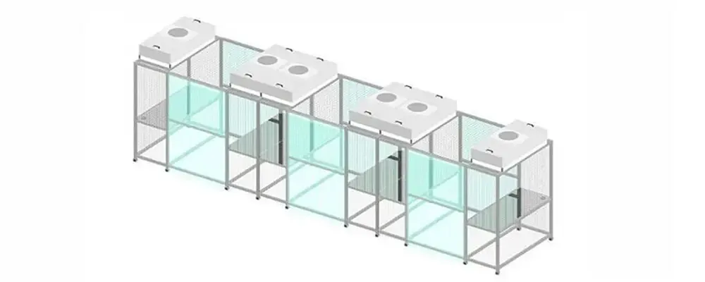
Particle Elimination
Deiiang™ FFU systems utilize high-capacity filters (up to 1220×610×69mm) to physically trap sub-micron particles, achieving strict ISO classifications through each Fan filter unit module.
Plenum Pressurization
By generating 190Pa static pressure, the Fan filter unit ensures consistent downward airflow that overcomes filter resistance—a hallmark of well-engineered FFU design.
FFU Fundamentals
FFU (Fan Filter Unit) integrates a fan and HEPA/ULPA filter. It draws air from ceiling plenums, pushes air through high-efficiency filters, and supplies purified air evenly to cleanrooms without central ductwork. Highly modular, clean air delivery unit arrays allow flexible scaling to meet varying cleanroom grades. Designed by Jason Peng, Deiiang™Fan filter units support tool-less filter change and hot-swappable motors for convenient operation.
Common Specifications and Parameters
Selecting the right FFU starts with understanding the three dominant form factors available on the market today. Each FFU size corresponds to specific airflow capacities and is suited to different cleanroom geometries. The table below summarizes the mainstream fan-powered filter module specifications that Deiiang™ and other leading manufacturers offer.
| FFU Type | Dimensions (mm) | Rated Airflow (m³/h) | Typical Application |
|---|---|---|---|
| Standard | 1175 × 575 × 320 | 1,400 | Large-area Class 100 workshops |
| Large | 1175 × 1175 × 350 | 2,800 | Open-bay halls, high-ceiling facilities |
| Compact | 575 × 575 × 320 | 700 | Small-area or localized Class 100 zones |
Filter Efficiency Grades for FFU Applications:
HEPA H14: ≥99.995% efficiency @ MPPS (~0.1–0.2 μm) — the standard choice for Class 100 FFU deployments
ULPA U15: ≥99.9995% efficiency @ 0.1 μm — required for Class 10 and semiconductor-grade FFU installations
For most pharmaceutical and electronics assembly fan-powered filter module projects, HEPA H14 filters strike the optimal balance between filtration performance and total cost of ownership. Deiiang™ supplies both H14 and U15 FFU configurations, with filter media sourced from certified ISO 29463-compliant manufacturers.
AC vs EC Motors: Which to Choose in 2026?
Selection of the Fan filter unit motor is probably the single most important decision when choosing FFUs. The type of motor used in fan-powered filter module determines their initial price as well as their operating expenses (in terms of energy and maintenance) throughout their lifetime. For very large FFU projects with more than 100 FFUs, the cost of EC motors becomes very reasonable and typical payback for electricity savings is within 12 to 24 months of continuous FFU operation. Below are typical values for key parameters for typical EC and induction motors. Note that typical noise figures for FFUs are based on measurements at a face velocity of 0.45 m/s. Of course, performance of actual FFUs on the market can vary greatly between manufacturers and even between models from a single manufacturer. And performance at different face velocities.
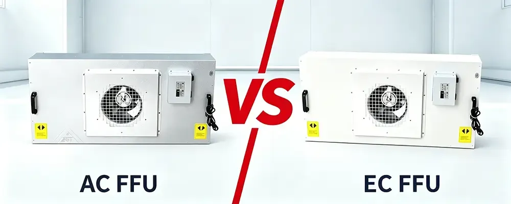
| Parameter | AC Induction Motor | EC Brushless DC Motor |
|---|---|---|
| Power Consumption | 180–250 W | 80–120 W |
| Speed Control | 3–5 fixed steps | Continuous (stepless) modulation |
| Noise Level | ≤55 dB(A) | ≤48 dB(A) |
| Group Control | Requires external monitoring add-on | Native intelligent group control support |
| Unit Price | Lower baseline | 30%–50% premium |
| Long-Term Energy Cost | Higher | ~50% lower electricity consumption |
Note: Noise values are typical; actual Fan filter unit performance depends on model and operating speed. Always consult manufacturer datasheets for project-specific FFU specifications.
EC motors are basically mandatory for FFU’s any more – ~50% energy savings to pay back the extra cost of an EC motor within 1-2 years of FFU’s runtime • 50-100 FFU’s: EC against AC – budget against group control functionality / need for energy monitoring. AC cheap for now, EC as normal for now – for now. Also, for any Fan filter unit project where monitoring from a remote location is required then EC is by far the simplest option. AC fan-powered filter module would require a full supervisory overlay system.
As of 2026, new fan-powered filter module installations will comprise more than 50% EC motor shipments compared to AC shipments. Deiiang™ strategy for new FFU projects is to design with EC first and AC as an alternative should cost be a major factor. Jason Peng, Deiiang™ Design Manager Jason Peng, noted that current FFU EC controllers have progressed to the point where they support a number of predictive maintenance algorithms, some of which can predict bearing wear and tear up to 600 hours in advance of actual failure. Jason is FFU Product Designer.
FFU Quantity Calculation
The number of Fan filter unit required for a Class 100 (iso 5) cleanroom using unidirectional airflow is determined from the face velocity supplied over the entire area of the supply. The FFU quantity supplied is critical. If too few are supplied the area will not meet the required cleanliness, and too many supplied will use unnecessary capital and consume excess amounts of energy. The standard FFU calculation formula is::
Worked Example — 100 m² class 100 cleanroom:
Face velocity v = 0.45 m/s (electronics industry standard for clean air delivery unit design)
Total required airflow = 0.45 × 100 × 3,600 = 162,000 m³/h
Using standard FFU units rated at 1,400 m³/h each: 162,000 ÷ 1,400 ≈ 116 ffu units
Add 10%–15% redundancy for operational flexibility: final FFU count ≈ 128–133 units
Fan filter unit Coverage Ratio (Full-Spread Rate): fan-powered filter module Coverage Ratio is a metric to determine the percentage of cleanroom ceiling area covered by FFU outlets. For Class 100 cleanrooms, the minimum coverage ratio is typically specified to be greater than or equal to 70%, while Front-end semiconductor processes require greater than or equal to 85% coverage ratio. Deiiang™ design team uses CFD simulation to model out the FFU coverage and subsequently design out the FFU grids.
Intelligent Group Control System
Standard clean air delivery unit arrays that are equipped with EC motors are combined with an intelligent group control system, thus turning the single fan-powered filter module into a clean air delivery system which is managed as a group from a central location by the respective control system. Managing single FFU’s without a group control system, that are installed in the ceiling, is usually very time consuming and can be very disruptive. Modern FFU group control systems manage to work with multiple FFU’s at the same time.
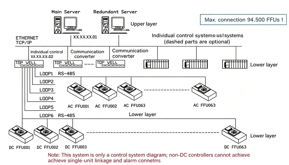
The Deiiang™ group control architecture, refined by Jason Peng through multiple product iterations, supports up to 2,000 Fan filter unit nodes on a single Ethernet backbone. Key capabilities include:
Centralized Speed Regulation — Adjust all FFU speeds from the control room; no need to access individual fan-powered filter module units on the ceiling
Fault Alarm & Diagnostics — Automatic alerts when any Fan filter unit fan stops or deviates from target RPM
Real-Time Energy Monitoring — Track per-fan-powered filter module power consumption and aggregate total Fan filter unit fleet energy usage
Zone-Based Partitioning — Assign different FFU speed profiles to different areas (e.g., high speed in active work zones, reduced speed in idle zones for energy savings)
Scheduled Strategies — Automatically reduce fan-powered filter module speed during non-production hours for significant energy conservation
FFU group control can use RS485, Ethernet or wireless protocols for communication. For new fan-powered filter module projects, Ethernet is recommended for better transmission reliability, easier commissioning and direct interface with BMS/BAS platforms. A 200-unit FFU system controlled by Ethernet can be fully commissioned within 4 hours, while a similar RS485 FFU network would take approximately 2-3 days to be fully commissioned.
FFU Maintenance Essentials
fan-powered filter module maintenance is critical to the cleanroom, to energy efficiency and to extending the life of your equipment. A well maintained FFU can last over a decade. A neglected FFU can develop filter bypass leakage or motor bearing failure within 3-4 years. The following FFU maintenance schedule is typical for the industry. FFU Filter Replacement Cycles:

HEPA H14 Fan filter unit filters: Typically 2–3 years (heavily dependent on pre-filtration quality and outdoor air conditions at the FFU intake)
ULPA U15 Fan filter unit filters: Typically 1.5–2 years due to tighter media and faster loading characteristics
When to replace Your FFU Filter:
Pressure drop across the fan-powered filter module filter reaches 1.5× to 2× the initial pressure drop
Airflow output from the fan-powered filter module drops by more than 20% (readily monitored via the group control system)
Routine FFU Inspection Protocol:
Monthly: Verify Fan filter unit operation indicators (or group control system status) for all units
Quarterly: Spot-check 10% of fan-powered filter module units with an anemometer to assess face velocity uniformity
Annually: Perform HEPA integrity testing on all clean air delivery unit filters (PAO or DOP challenge method per iso 14644-3)
Common FFU Troubleshooting Scenarios:
Individual Fan filter unit not running: Check the power connector and group control signal wiring at the fan-powered filter module terminal
Low FFU airflow: Likely a clogged filter or aging motor; verify with differential pressure measurement across the FFU
Abnormal Fan filter unit noise: Inspect for bearing wear or impeller looseness within the fan-powered filter module fan assembly
For FFU units in excess of 50 units Deiiang™ recommends the implementation of a digital maintenance log as part of the group control system. The filter loading rates of FFU filters can be analyzed in trends, and the replacement of clean air delivery unit filters can be scheduled in advance of airflow dropping to critical levels.
Advantages of Deiiang FFU Systems
Deiiang FFU modules can be easily integrated into your existing setup to improve its performance. With over 500 fan-powered filter module systems installed across the globe in the last 4 years (2023 – 2026), we at Deiiang FFU have come a long way. The knowledge we have gained, especially from our founder Jason Peng and the rest of the team designing Deiiang fan-powered filter module, have been encapsulated in the many updates of our FFU modules that we have released to date. Here are the areas where our FFU systems score in terms of improving overall performance of your setup:
Controlled Noise
Our optimized AC motor fan-powered filter module keeps operational noise between 55–63 dB, preventing operator fatigue in extended FFU runtime scenarios.
Compact Footprint
With heights as low as 230mm and 260mm, a Deiiang™ FFU fits into restricted ceiling plenums where standard fan-powered filter module cannot.
Robust Power
Running on 220V/50Hz, our fan-powered filter module models offer efficient power draws of 120W, 200W, or 230W.
Modularity
Need higher ISO classes? Simply drop an additional FFU into the ceiling grid—no HVAC duct redesign required.
FFU Airflow Dynamics
FFUs installed edge-to-edge of walls generate laminar airflow down through the cleanroom. This airflow is a uniform 0.45 m/s “air curtain” down through the space. For cleanroom classification levels of ISO 5 and below (less than 3520 particles/ft³ @ 0.5 μm), this type of airflow is critical in order to maintain particle counts at or below 3520 particles/m³ @ 0.5 μm. In non-critical areas of a cleanroom, Fan filter units are typically installed in a staggered pattern in order to create mixed/turbulent flow. This type of airflow injects high velocity clean air into the space that then dilutes the overall concentration of particles in the room prior to extraction by return FFUs. FFUs must be matched with the appropriate fan model for the required volume of airflow. Each FFU must be installed in the precisely correct location in order to meet the requirements of international cleanroom standards such as those found in iso 14644-1.
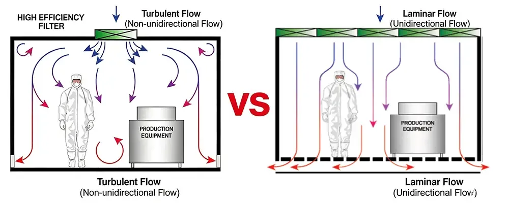
100% FFU CoverageMinimal turbulence Uniform 0.45 m/s descent
Partial FFU CoverageBetter mixing Dilution-based particle control
FFU Installation Locations
The spatial efficiency of an FFU is determined by how it is mounted. Most Fan filter units are installed into modular suspended ceilings. They come in standard sizes that match the T-grid dimensions found in ceiling grids all around the world. The smaller 575mm square FFUs are designed for wall mounting or for mounting on top of enclosed machinery to create an iso class 3 clean environment within a localized area. Deiiang™ supplies both T-grid ceiling FFUs and equipment mounted FFUs and the method of FFU mounting is determined by the depth of the plenum, the load on the structure and the required clean area dimensions.
T-Grid Ceiling FFU
Standard FFU sizes fit global T-grid ceilings. Ideal for whole-room FFU coverage.
View Fan filter units Ceiling Diagram →Equipment FFU Mounts
Compact FFU (575×575mm) for machinery integration and localized clean air delivery unit zones.
View Fan filter units Wall Diagram →Deiiang FFU Technical Specifications
Every process demands a specific Fan filter unit setup. Deiiang™ manufactures highly customizable fan-powered filter module solutions constructed with durable galvanized steel boxes to withstand continuous fan-powered filter module operation. Whether your FFU requires an ultra-thin 230mm profile or needs to push 2,000 m³/h, we deliver precision-engineered fan-powered filter module modules that integrate seamlessly into any cleanroom grid. The table below summarizes the key FFU parameters available across the Deiiang™ product line, designed under the supervision of Jason Peng:
| Parameter | Specification Range | Notes |
|---|---|---|
| Dimensions (W×L) | 575/615/920/1175/1225mm × 575/615/1175mm | Multiple FFU form factors available |
| Height Options | 230mm, 260mm | Ultra-thin FFU for tight plenums |
| Air Volume | 500, 600, 900, 1000, 1200, 2000 m³/h | Fan-dependent FFU output |
| Fan Models | #315, #400, #470 | AC current, matched to FFU size |
| Power Consumption | 120W, 200W, 230W | 220V/50Hz standard FFU supply |
| Noise Level | 55–63 dB | Measured at 0.45 m/s FFU face velocity |
| Vibration Coefficient | 0.2–0.5 | Critical for lithography-grade FFU |
| Static Pressure | 190Pa (10mmAq) | External FFU pressure rating |
| Filter Efficiency | 99.99%@0.3μm | HEPA-grade FFU media |
| Initial Pressure Loss | 110Pa@0.45m/s | Benchmark FFU filter spec |
Deiiang FFU Case Study: Electronics Cleanroom
A leading maker of microelectronics required the supply of an ISO class 5 cleanroom Fan filter unit array to be installed into a ceiling plenum of only 250mm in height. This required strict limits to be placed upon both vibration and noise to protect the lithography equipment. Deiiang supplied 500 no. of fan-powered filter module (so called ‘Ultra-thin’ style) of 1175mmw x 575mmd x 230mmb, all of which were customized to exacting client specified requirements. The key performances achieved by the FFUs were filtration to 99.99% @ 0.3μm and vibration coefficients of 0.2-0.5 or better.
FFU Case Study Summary:• Total cleanroom ffu units: 500 (‘ultra-thin’) fan-powered filter module models • Specific dimensions for each fan-powered filter module model: Length x Width x Height: 1175mm x 575mm x 230mm • FFU Model detailed specs: 120W, AC fan (#315), fan balancers, very low vibration, and very low noise • Filter: 1170mm x 570mm x 69mm and delivers 99.99% @ 0.3 microns efficiency • Cleanroom Class: Achieved verification of iso class 5 for all cleanroom FFU zones.
Project Site Documentation:
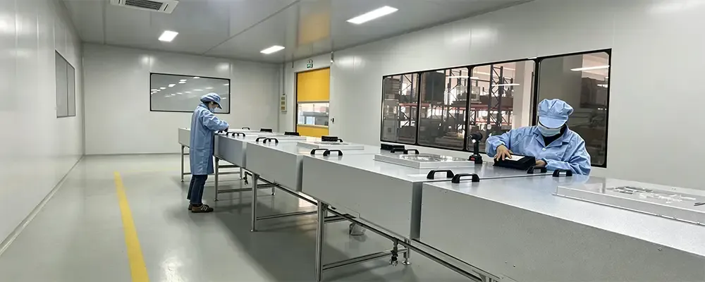
FFU Box Manufacturing
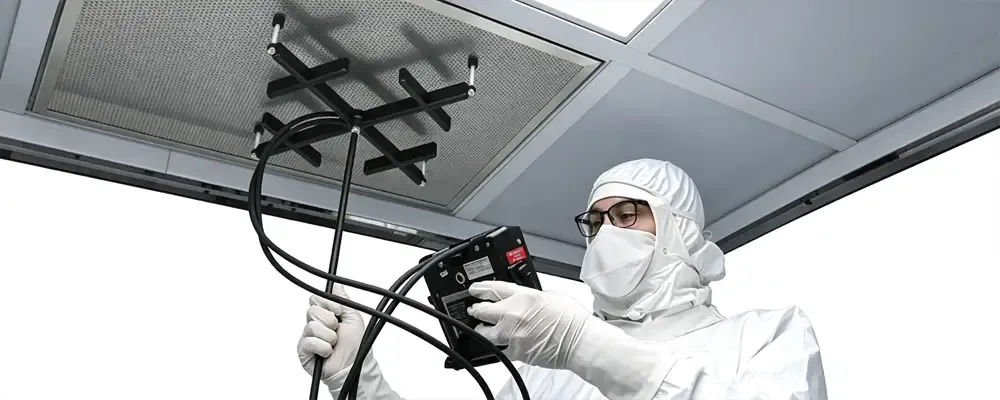
110Pa Drop FFU Testing

Grid FFU Installation
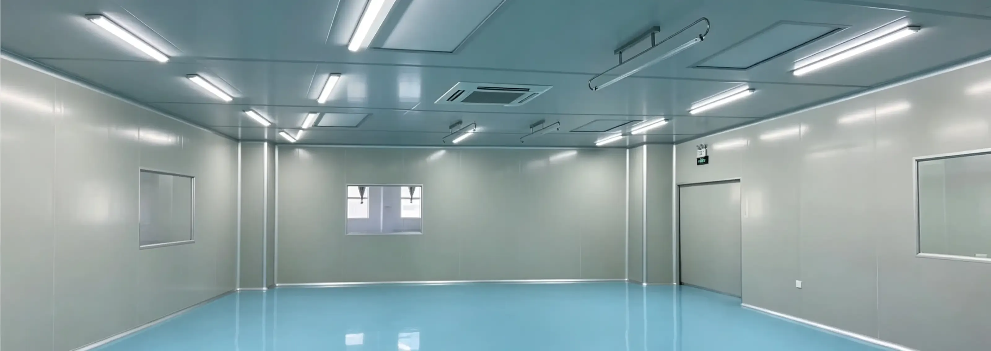
Finished FFU Cleanroom
We engineered this Deiiang Fan filter unit case study under Jason Peng, solving the typical cleanroom constraints of physical space and performance. Here 500 fan-powered filter module have been in continuous operation for 18+ months with 100% filter use and 0.45 m/s face velocity held constant.
FFUs by Deiiang have been qualified to deliver 99.99%@0.3μm clean air, 2000 m³/h airflow, and low vibration. Learn to select correct fan-powered filter module parameters to meet your cleanroom needs at www.cleanroomequips.com.
References
iso 14644-1:2015 — Cleanrooms and associated controlled environments — Part 1: Classification of air cleanliness by particle concentration. ISO Standards
iso 14644-3:2019 — Cleanrooms and associated controlled environments — Part 3: Test methods. ISO Standards
EN 1822-1:2019 — High efficiency air filters (EPA, HEPA and ULPA) — Part 1: Classification, performance testing, marking. CEN-CENELEC
IEST-RP-CC001.6 — HEPA and ULPA Filters. IEST Publications
Deiiang™ FFU Technical Documentation & Selection Resources. Deiiang™ Official
© 2026 Deiiang™ | Product Designer: Jason Peng | Fan filter unit Advanced Guide — 2026 Edition