+86 13638632902
 Jason@cleanroomequips.com


 MENU
MENU
Dampers and valves may both be found in HVAC applICations, but these two devices are different and should not be confused with eACH other. Dampers are used to control the flow of air in a duct while valves typically control the flow of water or some other fluid in a pipe. By understanding the differences between dampers and valves, one can better understand the drawings, specifications, and purchasing Requirements.
The major difference between dampers and valves is that dampers use blades to control the flow of air while valves use rotary devices to control the flow of fluids. The differences between dampers and vents, dampers and actuators, and dampers and louvers are similarly based upon the purpose of each device.
This discussion focuses on the types of dampers available, manufacturers of dampers, sizing dampers, actuation of dampers, and installation of dampers. One should always review the damper vs valve chart with the controls contractor to verify the intended application prior to making a purchase.
The short answer: a damper controls air inside ducts, a valve controls water or refrigerant inside pipes. Medium, mounting position and moving part all differ, and neither device can substitute for the other.
The Direct Answer in One Sentence
In a nutshell, the old rule applies: A damper allows for air control in ducts; a valve allows for water control in pipes.
The meaning is as simple as that – there are different medium, other types of devices, etc. This is how a valve vs damper comparison is presented – based on the used medium but not on the physical structure of the device.
Why This Distinction Matters on Site
Using the wrong device may result in pressure imbalance, commissioning problems, high costs and legal violations. Water valve in duct will not balance air properly; air damper in chilled water pipe will not be able to regulate the flow of water properly.
This is why any damper vs valve decision must start from the medium, not from the shape of the body or the flange pattern.
What a Damper Is and What It Does
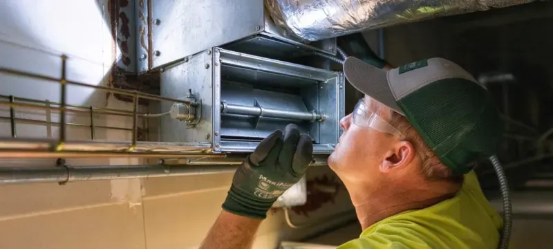
Damper refers to a structure installed within ductwork and performing tasks of airflow regulation through the rotation of blades in the duct's cross-section. A damper is always installed within the duct, in the upstream section before a device used for final air distribution.
The rotation of blades changes the size of the cross-section, resulting in a different pressure drop. A partially closed damper creates resistance that hampers airflow through the branch. Therefore, we can say that the main difference between damper and valve lies in their structure.
The density of air is approximately 1.2 kg/m³. At the same time, density of water equals 1000 kg/m³. Such a 800:1 ratio explains why damper actuators are expressed in Nm in relation to blade area and pressure drop, not pipe size.
Typical tasks performed by duct dampers:
- Carry out balancing of airflows to the branches
- Shut down or throttle the duct run
- Prevent reverse flow
- Control the pressure
- Close upon reception of fire or smoke signal
Damper Anatomy and Working Principle
The frame of a damper is responsible for carrying blades, the shaft, bearings, and seals. The shaft passes through the frame and connects to the actuator.
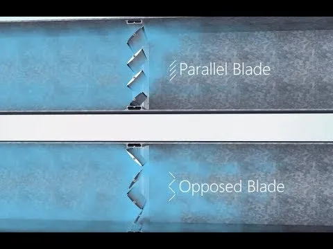
Blades rotate together using a linkage system. Opposed blades are rotated opposite to each other, and parallel blades rotate synchronically.
The edge of the blades seals the frame. When blades are closed, the cross-section drops to almost 0, but there is still a small gap left.
The Deiiang catalog indicates that the non-sealing gap between blades and frame is less than 2 mm. In case of a multi-leaf damper bigger than 1.2 m² in size, it is delivered either assembled or in segments so that the blades don't twist.
Frame, blade, shaft, bearing, seal, and linkage form a single mechanical chain. If any link is broken, it leads to leakage or jamming.
What a Damper Is Not — Clearing Common Confusions
There is a misconception that damper and vent are synonymous. However, the reality is that damper is present in the duct and is responsible for the control of airflow while a vent is the outlet of the duct. In this context, the difference between damper and vent lies in location and capability.
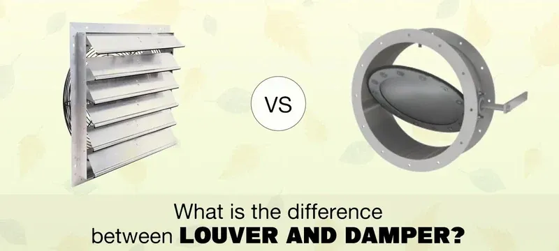
Another misconception is that damper and louver mean the same thing. In reality, a louver has fixed blades to provide protection from weather elements. In this context the difference between damper and louver relates to control vs. protection.
Many people think that damper and actuator are one and the same product. In fact it is a damper that consists of blades. The difference between damper and actuator is that the actuator performs the job of moving the blades.
One more misconception is that damper and the bread are related to each other just because of the spelling. In fact bread is a Food item.
In short, if you search for what is the difference between damper and bread you will see that there is only spelling similarity of these two items, otherwise they are totally different from the functional point of view.
Another aspect of the difference between damper and vent hvac equipment is how they are cleaned. A vent can be accessed easily from the walls of the room, while in case of a damper it is necessary to access it from inside the duct.
Regarding search clarity, the difference between damper and vent hvac damper vs vent question suggests one thing: the damper controls airflow whereas the vent brings it in and/or lets air out.
Damper Types and Where Each One Belongs
The question of valve versus damper is often raised during the purchase process, when a customer looks at the product. There are several types of dampers in terms of classification, which include volume control dampers, fire-dampers, smoke-dampers, backdraft dampers, pressure relief dampers, and zone dampers.
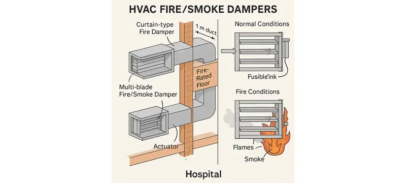
Volume control dampers are the simplest dampers, and they are designed for balancing. Fire-dampers and smoke-dampers are considered life-saving equipment depending on the standards of UL 555 and UL 555S.
Backdraft, pressure relief and zone dampers are more technical dampers, which were created to resolve a particular flow problem rather than for balancing air within the system. Each group of dampers has their own class based on their working duty as well as the classification of leakage and sometimes standards concerning them.
Table 1: Types of Dampers and Their Main Purpose
| Type of Damper | Main Purpose | Where It Is Installed |
|---|---|---|
| Volume Control | Dampers are used for controlling the air flow in the system. | Branch duct |
| Fire | Damper is used to ensure that fire does not spread in the buildings. | Fire compartment wall |
| Smoke | Damper limits smoke movement between compartments. | Smoke compartment |
| Backdraft | Dampers are used to prevent air flow in reverse direction. | Fan outlet |
| Pressure relief | Dampers are used to reduce excessive pressure in the air ducts. | Return or relief path |
| Zone | Dampers are used to control the air flow in each zone. | Zone branch |
| Type of Damper | Main Purpose | Where It Is Installed |
|---|---|---|
| Volume Control | Controls air flow in the system. | Branch duct |
| Fire | Stops fire spreading in buildings. | Fire wall |
| Smoke | Limits smoke movement. | Smoke compartment |
| Backdraft | Prevents reverse air flow. | Fan outlet |
| Pressure relief | Reduces excessive duct pressure. | Return path |
| Zone | Controls air flow per zone. | Zone branch |
Volume Control Dampers (VCDs) — The Workhorses of Air Balancing
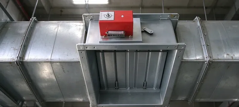
The special dampers that are used for air balancing purposes are called VCDs. There are different designs of dampers. There are single-blade and multi-blade dampers.
If opposed blade dampers are used, the curve will be very smooth and therefore, they can be successfully used in modulating duty. If parallel dampers are used, the curve will be surface visible, and they will be successfully used in on/off duty.
A manual locking quadrant is used to fix the angle of the damper. A clean room balancing team makes use of VCDs to create a trim for air flow in each branch according to the design in use.
Various configurations of VCD can be found:
- Single-blade used for small ducts.
- Multi-blade opposed for stable control.
- Multi-blade parallel used for shutoff bias.
- Manual quadrant – convenient type.
- Motorised – used with BMS system.
Fire, Smoke and Combination Dampers — Life Safety Devices
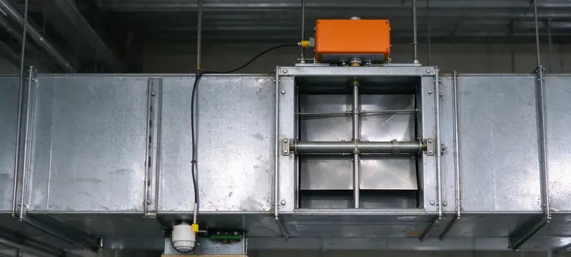
Fire dampers are tested under UL 555 [5] standards and installed according to NFPA 90A [7]. Smoke dampers are tested under UL 555S [6] standards and used according to NFPA 92 [8].
In Europe, fire damper products are covered by EN 15650 [10]. The installation regulations for dampers are issued by the IMC [11] and IBC [12] codes in the USA.
Every standard has its range: UL 555 is for fire dampers, UL 555S is for smoke dampers, NFPA 90A is for HVAC installations, and NFPA 92 is used in smoke control systems.
EN 15650 covers European fire damper products, as IMC and IBC determine the application of US regulations. The contractor has to understand each standard before submitting the document.
A thermal release closes at 72 °C or 165 °F a fire damper, that has combined fire and smoke dampers with a smoke detector signal.
Backdraft, Pressure Relief and Zone Dampers
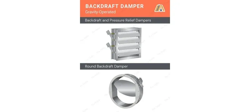
These dampers work according to the pressure differential threshold rather than control signals. The blade moves as soon as the threshold is passed.
Backdraft damper with 50 Pa of cracking pressure opens when the fan's static pressure reaches this value. Pressure relief damper opens in case the pressure in the room goes over its preset level.
- Zone damper is used in case of zoning comfort systems; as a rule, it employs a spring-return actuator.
- Bypass damper works to divert surplus air in DV systems.
- Pressure relief damper helps to protect the cleanroom/lab from pressure levels exceeding their limits.
Damper Type vs Duty and Leakage — Selection Table
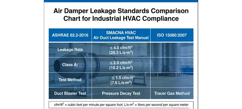
The catalogue of Deiiang has disclosed that the general leak rate is lower than 2% whereas the airtight leak rate is lower than 0.5%, complying with JB/T 7228-94 [15]. It should be noted that these values are entries in the catalogue and hence, not the direct outcome of measurement performed on one damper.
The catalogue of Deiiang states that the leak rate is evaluated according to JB/T 7228-94 at the stipulated reference pressure. In contrast, the AMCA 500-D class 1 and EN 1751 class 4 designate independent third-party methodologies.
These two methodologies do not have the same meaning. The use of the Deiiang percentage does not mean that AMCA or EN class can be chosen.
Table 2: Damper Type Compared to Duty and Leakage
| Damper Type | Duty | Leakage Class | Standards | Common Application |
|---|---|---|---|---|
| General volume controller | Measure | <2% (catalogue) | JB/T 7228-94 | Office branch |
| Airtight volume controller | Measure | <0.5% (catalogue) | JB/T 7228-94 | Cleanroom |
| Fire damper | Measure | According to UL 555 | UL 555 | Wall penetration |
| Smoke damper | Measure | According to UL 555S | UL 555S | Corridor |
| Backdraft | Measure | Not rated | – | Fan outlet |
| Pressure relief | Measure | Application specific | – | Lab |
| Zero leak damper | Measure | ≤0.05 m³/(h·m²) | JG/T 14-2010 [14] | Purification |
| Damper Type | Leakage Class | Standards |
|---|---|---|
| General volume controller | <2% (catalogue) | JB/T 7228-94 |
| Airtight volume controller | <0.5% (catalogue) | JB/T 7228-94 |
| Fire damper | According to UL 555 | UL 555 |
| Smoke damper | According to UL 555S | UL 555S |
| Backdraft | Not rated | – |
| Pressure relief | Application specific | – |
| Zero leak damper | ≤0.05 m³/(h·m²) | JG/T 14-2010 [14] |
How a Damper Actually Controls Airflow
A damper alters airflow through modifying free area and pressure loss. The angle of 0° signifies a complete openness of the blade, while the angle of 90° indicates total closure.
This comparison with valves does not hold any sense here since air is compressible and water is not. As a result, there is a difference in the shape of the control curve, which is a further part of the damper vs valve story.
The functioning of a damper is determined by the angle of the blade, free area, face velocity, system pressure, as well as the degree of leakage, whereas the authority and position are also of great importance.
Table 3: Trends for Blade Angle, Free Area, and Pressure Drop
| Blade Angle | Free Area | Pressure Drop Trend |
|---|---|---|
| 0° open | Maximum | Lowest |
| 30° | Reduced | Rising |
| 60° | Small | High |
| 90° closed | Near zero | Maximum |
| Blade Angle | Free Area | Pressure Drop Trend |
|---|---|---|
| 0° open | Maximum | Lowest |
| 30° | Reduced | Rising |
| 60° | Small | High |
| 90° closed | Near zero | Maximum |
Blade Angle, Free Area and Pressure Drop
Pressure drop increases with the square of velocity. Thus, for a doubling of face velocity from 750 to 1500 fpm, the pressure drop increases by a factor of about four.
A damper with a face velocity of 1500 fpm at a loss coefficient of 2.0 gives a pressure drop of about 0.9 in. w.g., while the same damper operates at about 0.22 in. w.g. at 750 fpm.
The coefficient will depend on the type of blade and, for multi-leaf dampers, should be in reality not less than 1.5-3.0 in the fully open position. The project-oriented value is furnished by the selection tables of the Deiiang catalogue.
It is that squared relationship, that's why the oversized face velocity creates noise and wastage of energy. Always follow the Deiiang catalogue guidance about keeping face velocity under 20 m/s in the fully open position.
Damper Authority and System Balance
Authority is the ratio of the pressure drop across the damper to the total pressure drop across the entire system. Low authority means that a damper does not control flow very well.
A pressure drop of 10 Pa across a 500 Pa system yields an authority of 0.02 and is considered poor. A pressure drop of 150 Pa yields authority of 0.30 with a better chance of it being workable.
Industry guidelines generally recommend a damper authority of at least 0.20 to 0.30, which ensures stable modulating control. Below 0.10, hunting and controllability issues are likely to occur.
Poor authority causes hunting, unstable branch flow and commissioning failures. Valves are sized based on authority as well, albeit with different numbers.
Leakage — The Metric That Separates Good Dampers from Bad Ones
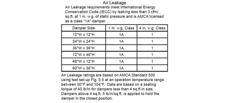
Leakage is measured by reference pressure, typically set at 250 Pa. ASHRAE 90.1 [2] specifies limits to leakage for certain types of dampers.
According to Table 6.4.3.4.3 of ASHRAE 90.1 the maximum permissible leakage is 4 cfm/ft² at 1 in. w.g. This corresponds approximately to 20.3 L/s·m² at the pressure of 249 Pa, as per AMCA 500-D.
The AMCA 500-D [4] and EN 1751 [9] classifications have been made so that there is a common understanding of the leakage values. The definition of zero-leakage is found in JG/T 14-2010 [14] which states this type to be of ≤0.05 m³/(h·m²).
Table 4: Comparison of Leakage Types
| Class of Leakage | Max Leakage at 250 Pa | Standard | Product in Deiiang |
|---|---|---|---|
| Standard duty | <2% (according to catalogue) | JB/T 7228-94 | Multi-leaf VCD |
| Airtight | <0.5% (according to catalogue) | JB/T 7228-94 | Airtight VCD |
| AMCA 500-D Class 1 | According to AMCA | AMCA 500-D | Airtight series |
| EN 1751 Class 4 | According to EN 1751 | EN 1751 | Airtight series |
| Zero-leakage | ≤0.05 m³/(h·m²) | JG/T 14-2010 | Sliding damper |
| Class of Leakage | Max Leakage at 250 Pa | Product in Deiiang |
|---|---|---|
| Standard duty | <2% (catalogue) | Multi-leaf VCD |
| Airtight | <0.5% (catalogue) | Airtight VCD |
| AMCA 500-D Class 1 | According to AMCA | Airtight series |
| EN 1751 Class 4 | According to EN 1751 | Airtight series |
| Zero-leakage | ≤0.05 m³/(h·m²) | Sliding damper |
Automatic vs Manual and Motorised Operation
Manual dampers are controlled with the help of a quadrant handle. Motorised dampers, on the other hand, work with an electric actuator. The difference between damper and actuator becomes apparent if the latter is taken out for servicing while the damper is still in the system.
Choosing between the two types depends on the frequency of changes needed in their position and if it has to be controlled by a BMS.
Table 5: Operation of Manual and Motorised Dampers
| Features | Manual | Motorised |
|---|---|---|
| Control | Quadrant Handle | Actuator |
| Power | None | 24 V and 230 V |
| Signal | None | On/off and modulating |
| Feedback | None | Optional |
| Fail-safe | Not applicable | Spring return |
| Cost | Low | Higher |
| Features | Manual | Motorised |
|---|---|---|
| Control | Quadrant Handle | Actuator |
| Power | None | 24 V and 230 V |
| Signal | None | On/off and modulating |
| Feedback | None | Optional |
| Fail-safe | Not applicable | Spring return |
| Cost | Low | Higher |
Manual Dampers — Set and Forget
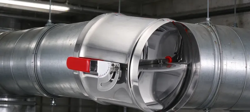
Manual dampers use a locking quadrant that keeps it in a position. There is no power required, and they are cheaper.
The commissioning teams put them in the desired position once. There's a lock present that prevents tampering.
Motorised Dampers — Actuators, Torque and Running Time
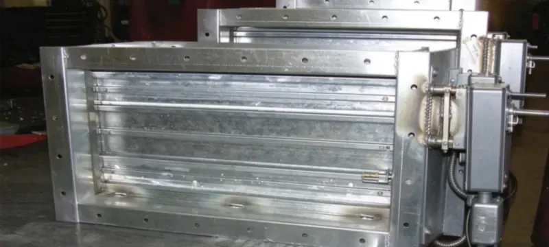
Motorised dampers have actuators that have ratings that vary between 4 Nm and 40 Nm for normal HVAC. The power used is generally 24 V and 230 V.
The spring return actuators move to their fail-safe position in case of failure of power. The running time can vary between 35 s and 150 s.
From the information provided by Deiiang catalogues, we have a standard AC 220 V actuator that operates at 8 W, 0.036 A, 30 N.m, IP67, and the running time is 20 s. Another model that is similar is high-torque DC 24 V that has specifications of 50 W, 3.57 A, and 250 N.m, IP67.
For the face area of the damper, 30 N.m model goes well with a damper size of 2-3 m². The model of 250 N.m would suit large multi-leaf dampers; we can check it against Deiiang torque selection table.
Deiiang Actuator Specifications for Cleanroom Duty
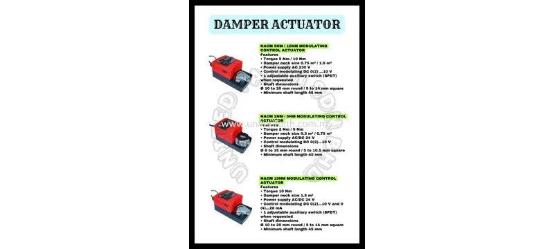
From Deiiang, we can find two models of actuators that exist in both 24 V and 230 V, with and without spring return. The pressure settings in a cleanroom imply that there must be variable control mode with soft closure for the purpose of preventing the disturbance of particles. The IP67 protection ranking is used when there are conditions of an extensive washout or moist air.
The types of control are on/off, passive contact, proportional and intelligent adjustment. The option of connecting BMS and BACnet exists.
The built-in measures of protection consist of limit switches, thermal overload protection, over-torque protection and anti-condensation heating. The running time is selected from the catalog, and the values are 5, 8, 15, 30, 50 or 100 seconds. The data concerning the Deiiang™ actuator has been collected by product designer Jason.peng.
Selecting and Sizing a Damper
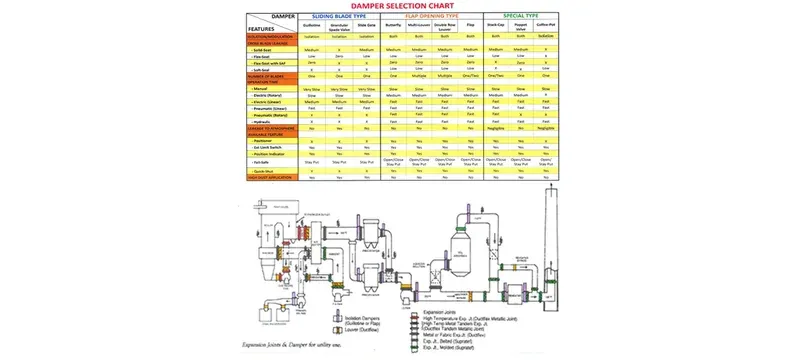
A damper sizing method differs from a valve sizing method, as they deal with different media. The process starts with determining some parameters of ducting: duct width, amount of air, pressure and the degree of leakage. After that, gauge the face velocity, torque and material.
Table 6: The Selection Scheme of Dampers According to Applications
| Application | Type of a Damper | Leakage Class | Actuator | Material |
|---|---|---|---|---|
| gmp cleanroom | Airtight type of a damper | <0.5% | 24 V type of actuator | Steel |
| Hospital | Fire/smoke | According to UL 555S standard | Spring return | Steel |
| Data center | Zone type of damper | Normal use | 24 V type of actuator | Steel |
| Laboratory | Pressure relief | Airtight type | Modulator | Stainless steel |
| Commercial office | VCD | Normal use | Manual or 24 V | Steel |
| Food Processing | Airtight sliding | Zero leakage | 24 V | Stainless steel |
| Application | Type of a Damper | Actuator |
|---|---|---|
| gmp cleanroom | Airtight damper | 24 V actuator |
| Hospital | Fire/smoke | Spring return |
| Data center | Zone damper | 24 V actuator |
| Laboratory | Pressure relief | Modulator |
| Commercial office | VCD | Manual or 24 V |
| Food processing | Airtight sliding | 24 V |
Sizing Procedure Step by Step
Actuator Sizing and Torque Calculation
Excluding unnecessary details, the formula for getting torque is torque = area of the blade * pressure difference * coefficient. The coefficient is defined by blade type and bearing friction.
For opposed blades, the coefficient will usually be from 0.008 to 0.015. Upon calculating and getting torque, select the most suitable Deiiang actuator class, which should be at least 20% above the needed torque.
To illustrate, a damper with an area of 4 m², pressure difference of 500 Pa and coefficient of 0.01 will give a torque of 20 Nm. The next suitable actuator class by Deiiang catalog should be selected after confirming the required dimensions of the actuator.
Damper Selection Matrix by Application
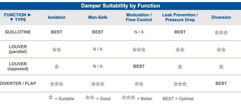
For cleanrooms and laboratory applications, it is required to have zero-leakage products. For commercial application area, standard dampers which can be manual and electrical are used.
The above-matrix can be used as one of the first points of reference. The final verification will include checking the torque and compatibility of the materials for the application.
Installation and Commissioning on Real Sites
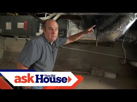
As far as the installation quality is concerned, it is guided by GB 50243-2016 standard. In addition to it, JG/T 14-2010 standard and JB/T 7228-94 standards must be presented in the task. SMACNA [3] rules can also be cited as a supplementary guide.
The difference between valve and damper is quite clear on site. Valves are installed on pipes, whereas dampers are installed in ducts. Knowing the difference between damper and vent hvac damper vs vent terminology will help to avoid mis-specifications.
Installation Requirements from GB 50243-2016
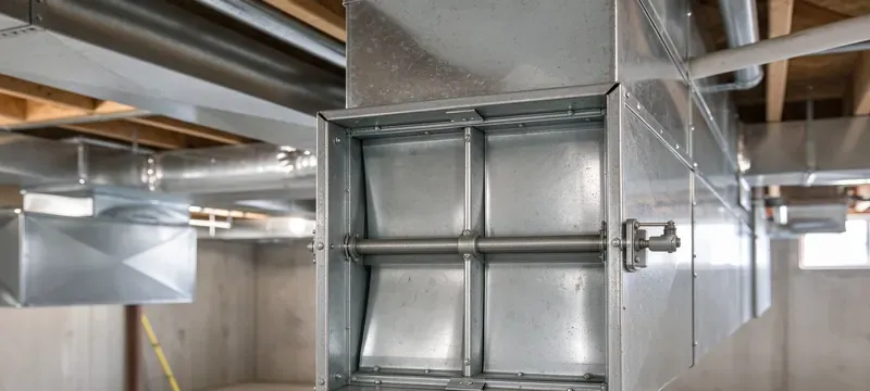
Common traps to avoid:
- Inserting an inclined slide valve against the air flow (Clause 6.3.8).
- Mounting that enables the horizontal sliding damper to operate with its panel open, instead of closing as a sliding damper should (Clause 6.3.8).
- Leaving gap between blade and frame at a distance more than 2 mm (Clause 5.2).
- Preventing access to the working mechanism (Clause 6.3.8).
- Embedding damper in the wall or structural component (Clause 5.2).
In addition to these rules, leave the operational face distance of 200 mm around it, and put the fire damper at a distance of up to 200 mm from the wall.
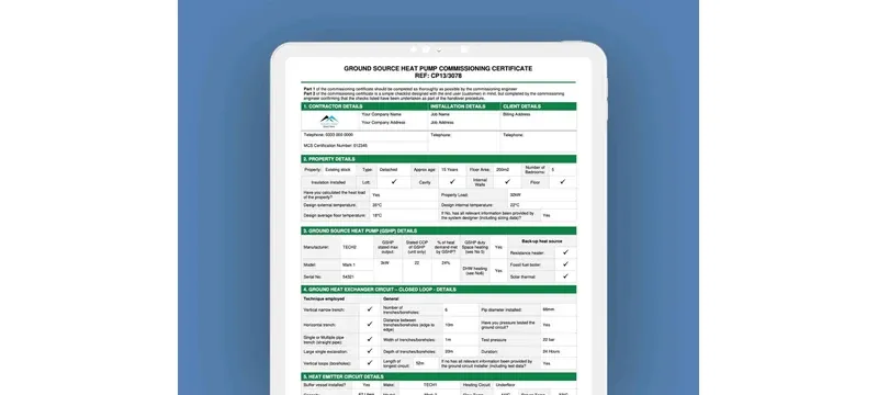
Commissioning Checklist for Dampers
Real-Project Case Study — Deiiang Cleanroom Damper Retrofit
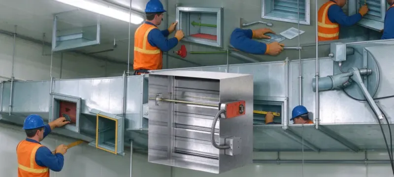
Information from the project: two clean room floors used Deiiang multi-leaf opposed-blade dampers connected to the room control system. Noise was reduced through using soft-close actuators.
Flow deviation in the air stream was measured at the test points and after balancing with a calibrated balometer. Observation period included one commissioning cycle with the logging of flow and pressure level in the system using the BMS.
In turn-down mode, the deviation of air flow was reduced from ±25% to ±10%. Room pressure was reported stable and during part load hours; the air stream operation occurred at lower static pressure level.
Common Faults and Mistakes on Site
In general, the cause of most damper issues is improper sizing, installation, or specification. Comparing the faults of dampers to those of actuators is useful while troubleshooting: dampers function mechanically, while actuators function electrically.
A damper vs valve specification mistake may turn out to be much more costly than a correction on-site.
Actuator and Control Faults
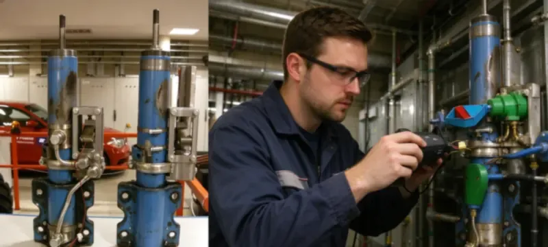
- Insufficient torque leads to incomplete step.
- The wrong fail-safe direction upon losing power.
- No feedback received by the BMS.
- Protocol mismatch with the BMS.
- Installation of actuator upside down or at an unsupported angle.
Installation and Commissioning Faults
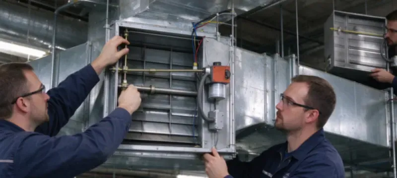
Typical traps on a real site:
- Duct insulation blocking the blade.
- A screw hitting blade during duct assembly.
- A quadrant handle located in an inaccessible position behind the ceiling.
- No airflow measurement holes made in the vicinity of the damper.
- No commissioning record after balancing.
Specification and Procurement Mistakes
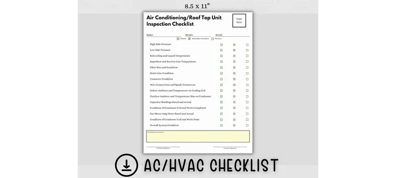
A frequent mistake is specifying standard-duty dampers instead of those requiring airtight performance. Check leakage class against the pressure regime and Contamination Control Requirements of the application.
Neglecting EN 1751 [9] class or not checking AMCA 500-D [4] data creates the risk of problems. It is better to ask for the test report or license number rather than believe in catalog claims.
Purchasing exclusively on the basis of price often results in heavy leakage, insufficient actuators, and repeated callouts. Make sure to calculate life cycle costs, including the costs associated with the energy wasted due to high leakage.
Frequently Asked Questions
These are the questions readers most often raise about damper vs valve selection and about how a damper differs from related duct components.
What is the difference between a damper and a valve in HVAC?
A damper manages airflow in ductworks while a valve manages refrigerants or water within the tubing system; therefore valve and damper cannot be used interchangeably.
What is the difference between a damper and a vent?
The damper is integrated in the duct and directs airflow whereas the vent is the last point of exit or entry at the limits of the room in which it can be a diffuser, a grille that returns the airflow back or can remove it from the space. The damper is always the first that comes in the duct opposite to the vent.
What is the difference between a damper and a louver?
The louver has immobile blades which are meant to stop outside weather from getting into the building. Louver may also use the drainable blade technology which protects it against rain which is impossible with dampers. A damper has moving blades and serves the purpose of airflow regulation.
What is the difference between a damper and an actuator?
The damper is the assembly that stops or allows the airflow while the actuator is the motor that makes the damper move thus providing force.
What is the difference between a damper and bread?
While bread is edible product, a damper is a device used in HVAC. So when telling the difference between damper and bread one must realize that there is only one difference responsible for the time consumption while researching.
What is the difference between damper and vent in HVAC damper vs vent?
The damper is used in the ductwork while the vent removes the air from the room. Therefore, the differences in damper and vent are caused by the functions rather than the products themselves.
References
- [1] ASHRAE 62.1 — Ventilation for Acceptable Indoor Air Quality.
- [2] ASHRAE 90.1 — Energy Standard for Buildings Except Low-Rise Residential Buildings.
- [3] SMACNA HVAC Duct construction Standards.
- [4] AMCA 500-D — Laboratory Methods of Testing Dampers for Rating.
- [5] UL 555 — Fire Dampers.
- [6] UL 555S — Smoke Dampers.
- [7] NFPA 90A — Installation of Air-Conditioning and Ventilating Systems.
- [8] NFPA 92 — Smoke Control Systems.
- [9] EN 1751 — Ventilation for Buildings — Air Terminal Devices.
- [10] EN 15650 — Ventilation for Buildings — Fire Dampers.
- [11] IMC — International Mechanical Code.
- [12] IBC — International Building Code.
- [13] GB 50243-2016 — Construction Quality Acceptance of Ventilation and Air Conditioning Works.
- [14] JG/T 14-2010 — Ventilation and Air Conditioning Air Terminals.
- [15] JB/T 7228-94 — Damper Leakage Test Method.