+86 13638632902
 Jason@cleanroomequips.com


 MENU

There are four steps required for measuring airflow speed and volume and calculating air exchange in clean rooms. The first step is calibrating the anemometer and establishing the sample points according to ISO 14644-3 [5]. The second step is to measure the velocity and calculate the total airflow into the room.
To divide the total airflow into the room to calculate the air exchange rate, you proceed to the third step. The fourth step is to check the compliance using the EU GMP Annex 1 [1].
This guide provides information on how to measure wind speed in clean rooms and how to calculate the total airflow volume for a clean room and pharmaceutical clean rooms. Clean room wind speed measurement, pharmaceutical cleanroom air volume calculation and air change rate calculation procedure are covered end to end.
The regulations used in this guide include EU GMP Annex 1, FDA 21 CFR Part 211, iso 14644 and USP <797> [1][2][3][6][7]. Deiiang field-validated techniques are utilized throughout.
Pharmaceutical Cleanroom Ventilation Standard Regulatory Framework
There are many levels to the pharmaceutical cleanroom ventilation standard, from European to North American to Chinese to the international standards. These standards are laid out in the following table.
Table 1: Cleanroom Ventilation Regulation
| Regulation | Scope | Air Exchange Rate |
|---|---|---|
| EU GMP Annex 1 (2023) | Sterile Medicinal Product | Grade A: 0.36 to 0.54 m/s (unidirectional); Grade B: ≥20 ACH (20–40 ACH typical design range); grade c/D: ≥20 ACH minimum [1] |
| FDA 21 CFR 211.46 | USA Drug Manufacturing | Adequate ventilation; HEPA filtered air in areas of concern at velocities sufficient to carry away particles [2] |
| ISO 14644-2:2015 | Cleanroom testing frequency and methods | iso class 5 and below: maximum of six months; ISO Class 6 and above: maximum of twelve months; requires calibrated instruments and documented methodologies [4] |
| USP <797> | Sterile Compounding | ISO 7 buffer room: ≥30 ACH total, ≥15 ACH from ceiling HEPA; PECs: 0.36–0.54 m/s unidirectional airflow [6] |
| GB 50073-2013 | China cleanroom design | Class 4 to Class 5 should use unidirectional flow; Class 6 to 9 have non-unidirectional flow but adhere to specific ACH range [7] |
| PIC/S GMP PE 009 | International Harmonization | Aligns with EU GMP Annex 1 for cleanroom qualification and airflow [8] |
| Regulation | Air Exchange Rate |
|---|---|
| EU GMP Annex 1 (2023) | Grade A: 0.36–0.54 m/s; Grade B: ≥20 ACH (20–40 typical); Grade C/D: ≥20 ACH [1] |
| FDA 21 CFR 211.46 | HEPA filtered air at velocities sufficient to carry away particles [2] |
| ISO 14644-2:2015 | Class 5 and below: 6 months; Class 6 and above: 12 months [4] |
| USP <797> | ISO 7 buffer: ≥30 ACH total, ≥15 ACH from ceiling HEPA; PECs 0.36–0.54 m/s [6] |
| GB 50073-2013 | Class 4–5 unidirectional; Class 6–9 non-unidirectional with ACH ranges [7] |
| PIC/S GMP PE 009 | Aligns with EU GMP Annex 1 [8] |
PEC velocity is measured using the same grid method as Grade A cleanroom testing. The same cleanroom air flow test method applies to any pharmaceutical cleanroom ventilation standard review.
cleanroom grade-by-Grade Ventilation Rate Requirements
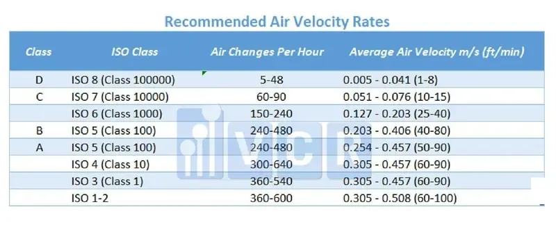
As previously stated, Grade A uses unidirectional flow velocity ranges. Grade B uses turbulent airflow with the primary air exchange rate. Table 2 outlines the Grade requirements.
Table 2: Cleanroom Ventilation Grades and Their Requirement
| Ventilation Grade | ISO Number | Type of Ventilation | Air Flow Rate/AH | Pressure Difference |
|---|---|---|---|---|
| A | iso 5 | Unidirectional | 0.36 to 0.54 m/s at working level | +15 Pa from Grade B |
| B | ISO 5 (static) / ISO 7 (dynamic) | Non-unidirectional | ACH ≥20 (between 20–40 for design purposes) | Between +10 and +15 Pa from Grade C |
| C | ISO 7 | Non-unidirectional | ACH ≥20 | +10 Pa from Grade D |
| D | iso 8 | Non-unidirectional | ACH ≥20 (guidelines) | +5 Pa from unclassified |
| Grade | Type of Ventilation | Air Flow Rate/AH |
|---|---|---|
| A | Unidirectional | 0.36 to 0.54 m/s at working level |
| B | Non-unidirectional | ACH ≥20 (20–40 for design) |
| C | Non-unidirectional | ACH ≥20 |
| D | Non-unidirectional | ACH ≥20 (guidelines) |
Coverage of cleanrooms is not the same during static and dynamic conditions, as Grade B covers ISO 5 in the static state and ISO 7 in dynamic operation.
GMP Mandatory Testing and Validation Frequencies
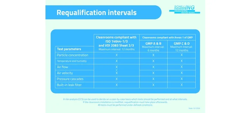
Initial commissioning of every sort includes full velocity of airflow, full volume, full ACH and pressure differential test before certifications of GMP.
Periodic re-validations to be done every six months for Class 5 and lower classes, and twelve months for Class 6 and higher classes [4].
- Regular monitoring to include monthly tests for velocity at critical points of A and quarterly tests for ACH in B and C.
- Retesting is done in case of deviation of filters, replacement of HVAC and out-of-range particle counts.
- Documentation includes raw data of every test file, including both signed and calibrated records.
- All audit trails must be kept for five years or longer.
Clean Room Wind Speed Measurement Full Procedure
The wind speed measurement in a clean room can be carried out according to a pre-determined sequence. Everything written here consists of instrument choice, sampling layout, implementation, and data recording, considering this process is different for one-way and two-way airflow rooms.
The velocity and ACH tests must be conducted in both conditions, resting mode and operating mode, according to the EU GMP Annex 1 [1]. Resting mode is when the unit operates without staff working in the room, while the operating mode simulates real product production.
The test methodology used in Deiiang field testing is based on the usage of a calibrated thermal anemometer having NIST traceable calibration. This cleanroom airflow velocity testing approach is the base of any gmp cleanroom ventilation measurement.
The sampling points layout will be horizontal, using a uniform distance of 15 cm–30 cm below the HEPA filter face according to ISO 14644-3 standard [5]. The grid in the case of a 592 mm × 592 mm diffuser consists of no less than 5 points.
Pre-Test Preparation and Equipment Calibration
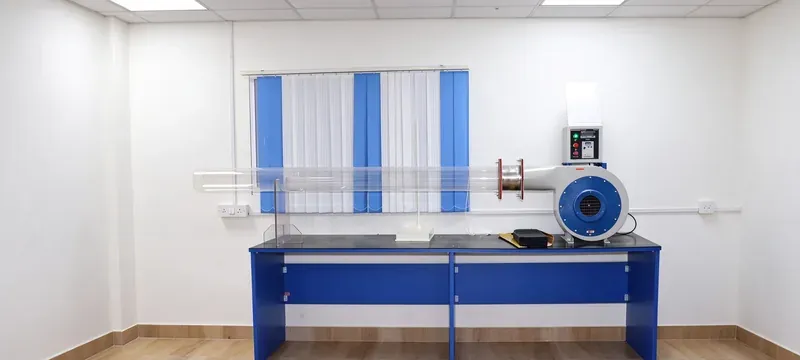
Pre-Testing Field Checklist:
Sampling Point Layout per ISO 14644-3
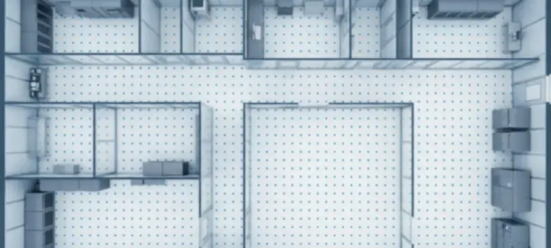
- The sampling points have to be at working height, usually about 0.8 m–1.2 m for non-unidirectional flows.
- In the case of unidirectional, tests have to be conducted at a distance of 15 cm–30 cm from the flow terminal [5].
- Follow the even grid; the number of points is calculated as 10×√S, where S is the net open filter area in m².
For example, if the effective area of the filter is 0.303 m², then 10 × √0.303 ≈ 5.5, rounded up to 6 points. This aligns with the 5-point minimum practice for clean room wind speed measurement.
- For supply diffusers, make sure there is one point in the center of each quadrant and in the geometrical center of the diffuser.
- Add return air grille point to verify the exhaust air flow balance.
- Make sure there is enough data for corner and edge coverage, as often the airflow at the extreme points of the room shows uniformity problems.
- For Deiiang's custom design, place the sampling points at the center of each equal area in the filter.
Table 3: Basic Sampling Points Required by Standard Filter Dimensions (ISO 14644-3)
| Filter Dimensions in mm | Sampling Points Required per ISO 14644-3 |
|---|---|
| 305 × 305 | 4 |
| 592 × 592 | 6 |
| 610 × 610 | 6 |
| 1170 × 570 | 8 |
| Filter Size (mm) | Sampling Points |
|---|---|
| 305 × 305 | 4 |
| 592 × 592 | 6 |
| 610 × 610 | 6 |
| 1170 × 570 | 8 |
Cleanroom Airflow Velocity Testing Execution Steps
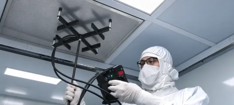
The face area of Deiiang's H14 Air diffuser, 592 × 592 mm, is 0.350 m². The expected face velocity is 2500 ÷ (0.350 × 3600) = 1.98 m/s at the filter face, which reduces to 0.45 m/s at the working position.
Pharmaceutical Cleanroom Air Volume Calculation Methods
There are two methods for pharmaceutical cleanroom air volume calculation: the diffuser velocity method and the duct traverse method. The diffuser method is the fastest and is used for routine GMP testing, while the duct traverse method is more accurate for validation and baseline studies.
Jason Peng, the Lead Product Designer at Deiiang, indicates that 75% of mistakes with on-site air volume calculations arise due to nominal filter sizes, as opposed to measured effective filter face area. This use of nominal measurements can lead to an overestimation of the ACH by as much as 10%.
It is important to always use the following basic formula to determine air volume: Air Volume (m³/h) = Velocity (m/s) × Effective Area (m²) × 3600.
When calculating air volume for multiple diffusers, each diffuser's air volume should be summed during the last stage of the calculation. Additionally, always apply the leakage correction factor of 0.95 to 0.98.
The HEPA module product data from Deiiang contains useful reference data. The combined high-efficiency filter 592 mm × 592 mm × 292 mm is rated at 1900 m³/h, with a media area of 15.03 m² and an initial resistance of ≤200 Pa (H13).
If one selects the 4-pleat version, the air volume will be 2500 m³/h, with an effective media area of 20.04 m². The dust-holding capacity of this unit is about 1200 g for the 2500 m³/h model.
Calculation from HEPA Diffuser Face Velocity
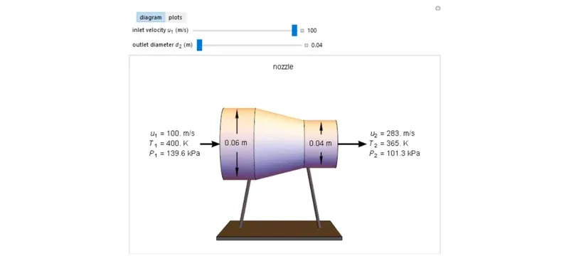
The effective diffuser area is the measurement taken using the filter frame dimensions instead of the nominal grid ceiling. In the case of the 592 × 592 mm filter, the actual face opening is approximately 0.550 × 0.550 m = 0.303 m², which takes into account the frame allowance.
Therefore, the air velocity formula is:
Where Q = air volume (m³/h), V = average face velocity in meters per second (m/s), A = effective area (m²).
For example, if a Deiiang H14 diffuser measures 592 × 592 mm and has an effective area of 0.303 m², and the average face velocity is 1.80 m/s, that leads to an air volume of 1963 m³/h.
Applying the leakage correction factor of 0.97 results in 1904 m³/h, which corresponds to the 1900 m³/h presented in the catalogue.
If the temperature is higher than 25°C or the elevation is more than 1000 meters above sea level, use the density correction factor (293 / T) × (P / 101.3), where T is the air temperature in Kelvin and P is the barometric pressure in kPa.
Deiiang field experience suggests that this density correction is bypassed regularly by many Southeast Asian facilities, which then distorts the finished pharmaceutical cleanroom air volume calculation.
Duct Traverse Air Volume Verification Method
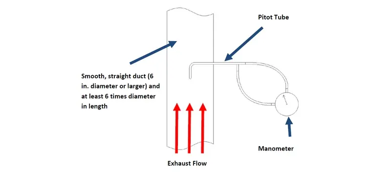
- Make use of a Pitot tube to determine velocity pressure in various places across the duct cross-section.
- Divide the duct into equal-area zones; the number of points is based on duct size.
- Apply air density correction: V = √(2 × ΔP / ρ), where ρ = 1.2 kg/m³ in standard conditions.
- Obtain the average velocity from the average velocity pressure.
- Work out total volume: Q = V_avg × A_duct × 3600.
- Check duct traverse against diffuser face velocity; a difference of ±10% is acceptable.
For example, for a 300 mm × 300 mm duct with an average velocity of 5.75 m/s: Q = 5.75 × 0.09 × 3600 = 1863 m³/h. This matches the same 592 mm diffuser discussed above.
Table 4: Air Volume Calculation Comparison — Diffuser vs. Duct Traverse (Same 592 mm Diffuser Unit)
| Method | Input Data | Calculated Volume | Agreement |
|---|---|---|---|
| Diffuser Face Velocity | V = 1.80 m/s, A = 0.303 m² | 1963 m³/h (raw) | Reference |
| Diffuser Leakage Adjusted | × 0.97 | 1904 m³/h | Reference |
| Duct Traverse | V_avg = 5.75 m/s, A = 0.09 m² | 1863 m³/h | 2.2% vs. adjusted diffuser |
| Method | Calculated Volume | Agreement |
|---|---|---|
| Diffuser Face Velocity | 1963 m³/h (raw) | Reference |
| Diffuser Leakage Adjusted | 1904 m³/h | Reference |
| Duct Traverse | 1863 m³/h | 2.2% vs. adjusted diffuser |
Ventilation Frequency Calculation Cleanroom Step-by-Step
Ventilation frequency calculation cleanroom, or air change rate calculation, begins after the air volume is calculated. The formula is ACH = total supply airflow volume (m³/h) / net room volume (m³).
The concept of ACH does not apply to unidirectional flow, since the airflow occurs in plug flow rather than turbulent mixing. For reference purposes only, a Grade A unidirectional flow has an approximate range of 300 to 500 equivalent ACH.
In cleanroom volume calculations, the net volume does not include equipment, columns, etc. The gross volume is determined by room dimensions (6 m × 4 m × 3 m = 72 m³). If equipment takes up 5 m³, the net volume equals 67 m³.
Thus, with 2000 m³/h of airflow, ACH would equal 2000 / 67 = 29.9. Turbulent rooms use ACH; unidirectional rooms use velocity.
Air Change Rate Calculation Procedure Full Workflow
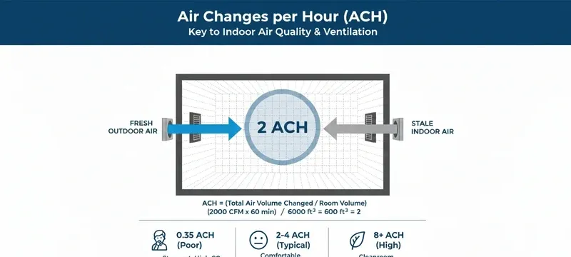
Use only supply air volume for ACH calculation per GMP convention; return air volume is used only for airflow balance verification.
- To determine the total net internal room volume, use the following equation: volume = length × width × height minus all internal equipment and fixtures that take away volume.
- Total supply airflow should be calculated by summing the volume of all devices like supply fans and HEPA units installed inside the cleanroom.
- The raw ACH is calculated as total supply airflow divided by the net room volume.
- If the airflow is expressed in terms of minutes, convert it into the rate per hour by multiplying by 60.
- Apply the leakage adjustment factor of 0.95 to 0.98.
- Check final ACH against the corresponding standard grade value: Grade B – ≥20, Grade C – ≥20, and Grade D – ≥20 [1].
This air change rate calculation procedure is the same one auditors expect to see documented in any gmp cleanroom ventilation measurement report.
How to Calculate air changes in Clean Room: Worked Example
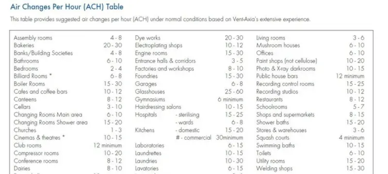
Let us take a Grade C sample room with dimensions of 6 m × 4 m × 3 m, equipped with 4 m³ of interior machinery. Therefore, the net volume of the sample room is 72 − 4 = 68 m³.
Total airflow came to 7600 m³/h, consisting of 4 units of Deiiang H13 diffusers, each having a capacity of 1900 m³/h.
Dividing 7600 by the net room volume 68 gives a raw ACH of 111.8. Applying the leakage factor of 0.97 adjusts the ACH to 108.4, which is far above the required Grade level of 20 ACH. This is how to calculate air changes in clean room work in practice.
One can summarize all the relevant ACH calculations in a table format as shown below.
Table 5: Sample Working ACH Calculation
| Parameter | Value |
|---|---|
| Room dimensions | 6 m × 4 m × 3 m |
| Gross volume | 72 m³ |
| Equipment displacement | 4 m³ |
| Net volume | 68 m³ |
| Total supply airflow | 7600 m³/h |
| Raw ACH | 111.8 |
| Leakage-adjusted ACH | 108.4 |
| EU GMP Grade C minimum | 20 ACH |
| Compliance | Pass (5.4× minimum) |
| Parameter | Value |
|---|---|
| Room dimensions | 6 m × 4 m × 3 m |
| Gross volume | 72 m³ |
| Equipment displacement | 4 m³ |
| Net volume | 68 m³ |
| Total supply airflow | 7600 m³/h |
| Raw ACH | 111.8 |
| Leakage-adjusted ACH | 108.4 |
| EU GMP Grade C minimum | 20 ACH |
| Compliance | Pass (5.4× minimum) |
GMP Cleanroom Ventilation Measurement Quality Control
Cleanroom ventilation measurement of gmp cleanrooms assures quality control, with cleanroom ventilation being in line with applicable regulations. Some of the common sources of error include incorrect telemetry height, unstable airflow before the test is run, and people blocking the airflow.
All of these can result in a large margin of error in velocity readings, so GMP cleanroom ventilation measurement depends on disciplined technique.
According to the regulations, all readings obtained and recorded must be checked against the grade. Any readings below 0.36 m/s for Grade A show that further investigation is required.
In the case of non-unidirectional rooms, all values below the minimum threshold must either increase airflow or come with robust justification in writing.
In the QA measures of Deiiang, every DOP scan of the HEPA filter is completed before it leaves the facility. The 592 × 592 × 292 mm filter is sealed for testing at 99.995 to 99.999% efficiency at 0.3 µm before it is shipped and catalogued.
Common Pitfalls in Cleanroom Air Flow Test Method
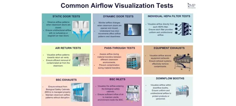
- Incorrect test height: the correct test height is 15–30 cm downstream from the filter face, not at the filter face itself.
- Pre-testing airflow not stable: no records should be taken before HVAC stabilization.
- People blocking airflow: being within the flow produces a 10 to 30% error rate.
- Calibration of testing instruments not adequate: instrument calibration may have expired, causing drift up to 15%.
- Missed pressure impacts of room: mistakes are made if the pressure of the cleanroom is not equal to its designed pressure.
- Calculating with the nominal dimensions of the filters rather than the actual flap opening.
- Blocked openings from return grilles: if the pre-filters are blocked, the effective airflow reduction can reach 25% at acceptable delivery speeds.
- Unbalanced exhaust flow: too much exhaust causes room negative pressure that pulls in unfiltered air. Confirm the supply-exhaust balance matches the design differential.
For example, Deiiang had a Grade C oral solids dosage facility in 2025 with ACH readings 18% below design. Deiiang engineers traced this problem to a miscalculation of effective filter area, since they used nominal rather than actual openings.
Once this was done, the readings returned to specification without having to make any changes to the fans. This has been documented in the project report and confirms the value of a strict cleanroom air flow test method.
GMP Validation Documentation Requirements
- The test report must include the room ID, grade, date, instrument ID, and calibration due date.
- Each instrument must have a copy of the calibration certificate attached.
- The raw data sheets must show every individual velocity reading and calculated average.
- Records of deviations must be maintained as CAPA records for any out-of-spec result.
- The report must be signed by qualified QA and engineering personnel.
- The standard report template for Deiiang has all of the required fields as outlined in EU GMP Annex 1.
Frequently Asked Questions
What is the minimum air change rate for grade c cleanrooms?
According to EU GMP Annex 1, the minimum ACH rate for a Grade C cleanroom is 20 ACH [1]. Design ranges are typically between 25 and 35 ACH, depending upon the heat load and particle generation. Deiiang usually recommends pharmaceutical Grade C cleanrooms be designed for 25 to 30 ACH and have a pressure differential from adjacent lower-grade areas of 10 to 15 Pa.
How often should clean room wind speed measurement be performed?
Initial commissioning should be a full mapping of all velocities prior to release for GMP compliance. Subsequently, revalidations will be every year for ISO Class 6 and higher, and every six months for ISO Class 5 and lower [4]. Routine monthly monitoring at Grade A critical points is standard. Should a filter be changed or an alteration made to the HVAC system, retesting would be mandatory.
Can I use a handheld anemometer for GMP validation testing?
Yes, a handheld anemometer calibrated in accordance with NIST, coupled with documentation of the instrument ID and calibration date, would be acceptable. However, fixed monitoring systems are preferred, as they allow for continuous monitoring of Grade A parameters. Handheld devices may still apply, but periodic validation serving to document instrument traceability is required.
Why is leakage factor included in air volume calculation?
Duct and filter frame leakages mean that the actual volume of air reaching the cleanroom is diminished. A leakage factor of 0.95–0.98 accounts for this loss of volume. Without such adjustment, the calculated ACH would indicate between 2–5% more than what taking adjustments into consideration reveals, thus creating the possibility of missing a noncompliance gap.
What is the difference between airflow velocity and air change rate?
Airflow velocity is the speed of the flow of air at any given point in meters per second (m/s). Air change rates report the total number of complete room volume exchanges per hour. Unidirectional rooms are usually monitored with airflow velocity since airflow is always within a specifically assigned direction. Non-unidirectional rooms are monitored using ACH, since the air moves about the room in an indiscriminate manner.
Do ISO 14644 and EU GMP have identical ventilation requirements?
The essential requirements associated with the two guidelines are closely aligned; however, differences do exist. ISO 14644-2 specifies the frequency of testing, the method of testing, and documentation practices [4]. The EU GMP Annex 1 specifies pharmaceutical-oriented unique regulations regarding unidirectional airflow velocities in Grade A critical environments and the differential pressure between the various grades [1].
References
- [1] EU GMP Annex 1 (2023) — Manufacture of Sterile Medicinal Products. https://health.ec.europa.eu/latest-updates/revision-eu-guidelines-good-manufacturing-practice-medicinal-products-manufacture-sterile-2022-08-25_en
- [2] FDA 21 CFR 211.46 — Ventilation, Air Filtration, Air Heating and Cooling. https://www.ecfr.gov/current/title-21/chapter-I/subchapter-C/part-211/subpart-C/section-211.46
- [3] iso 14644-1:2015 — Classification of Air Cleanliness by Particle Concentration. https://www.iso.org/standard/53394.html
- [4] ISO 14644-2:2015 — Monitoring to Provide Evidence of Cleanroom Performance. https://www.iso.org/standard/53395.html
- [5] iso 14644-3:2019 — Test Methods for Cleanrooms and Associated Controlled Environments. https://www.iso.org/standard/53396.html
- [6] USP <797> — Pharmaceutical Compounding: Sterile Preparations. https://www.usp.org/compounding/general-chapter-797
- [7] GB 50073-2013 — Code for Design of Clean Room (China). https://www.chinesestandard.net/PDF.aspx/GB50073-2013
- [8] PIC/S GMP Guide PE 009 — Guide to Good Manufacturing Practice for Medicinal Products. https://picscheme.org/en/publications?tri=gmp
- [9] ISO 16890:2016 — air filters for General Ventilation. https://www.iso.org/standard/65054.html
- [10] EN 1822:2019 — High Efficiency Air Filters (EPA, HEPA and ULPA). https://www.iso.org/standard/73720.html