1. Light leakage detection

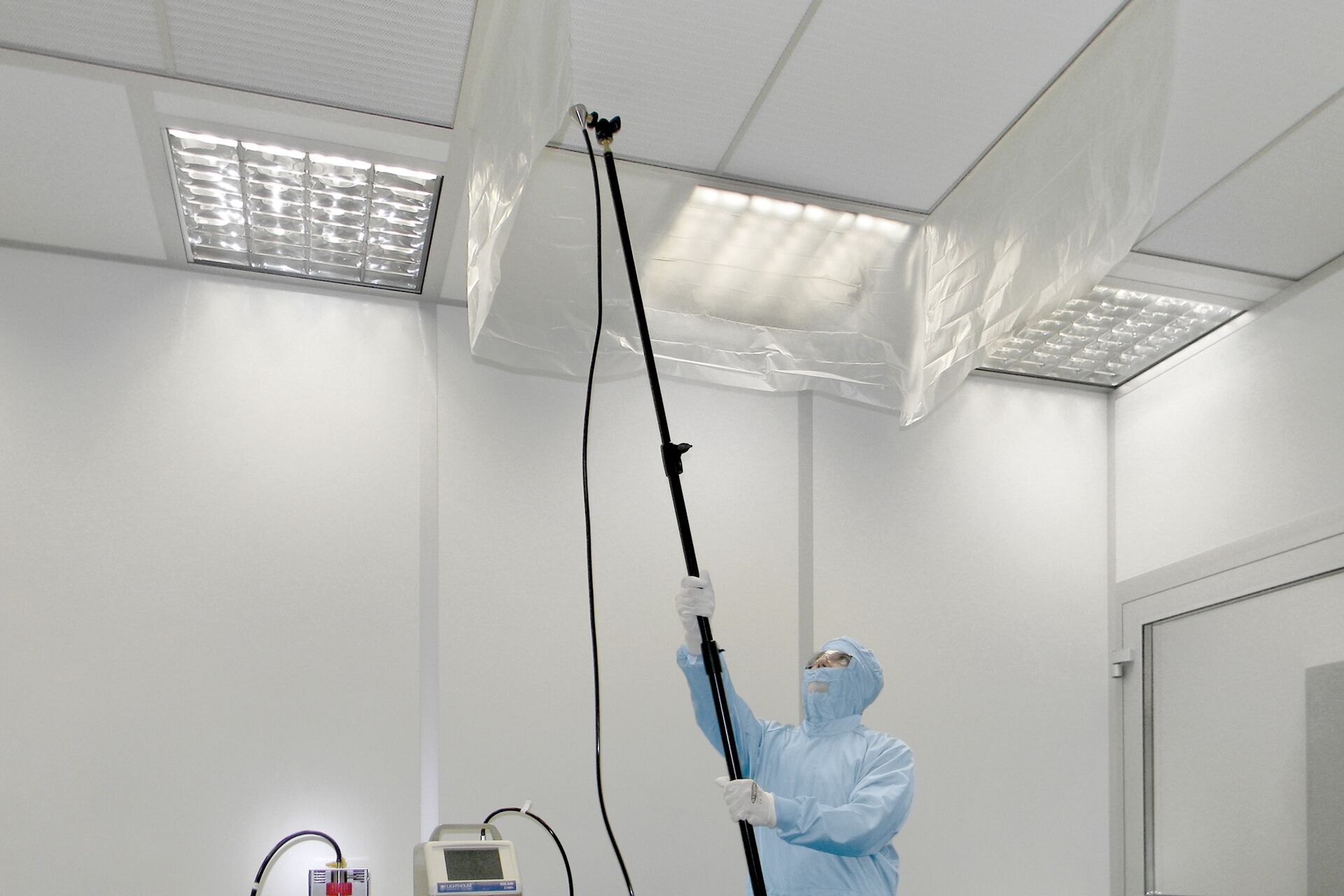
1.1 Light leakage detection is a method of detecting
the tightness of system air ducts by using the strong penetration of light
through small holes.
1.2 The detection should use a safe light source with a certain intensity. The handheld mobile light source can use a low-voltage lighting lamp with a protective cover of not less than 100W, or other low-voltage light sources.
1.3 When detecting light leakage of system air ducts, the light source can be placed on the inside or outside of the air duct, but the opposite side should be a dark environment. The detection light source should be moved slowly along the interface and seam to be detected, and observed on the other side. When light is found to be emitted, it means that an obvious air leak has been found, and records should be kept.
1.4. For the detection of system air ducts, it is advisable to adopt the method of segmented detection and summary analysis. On the basis of strict installation quality management, the detection of system air ducts is mainly based on the main pipe and trunk pipe.
When the light leakage method is used to detect the tightness of the system, the low-pressure system air duct is qualified if there are no more than 2 light leakage points per 10m joint, and no more than 16 light leakage points per 100m joint on average; the medium-pressure system air duct is qualified if there are no more than 1 light leakage point per 10m joint, and no more than 8 light leakage points per 100m joint on average.
1.5 The strip-shaped light leakage found in the light leakage detection should be sealed.
2. Test device

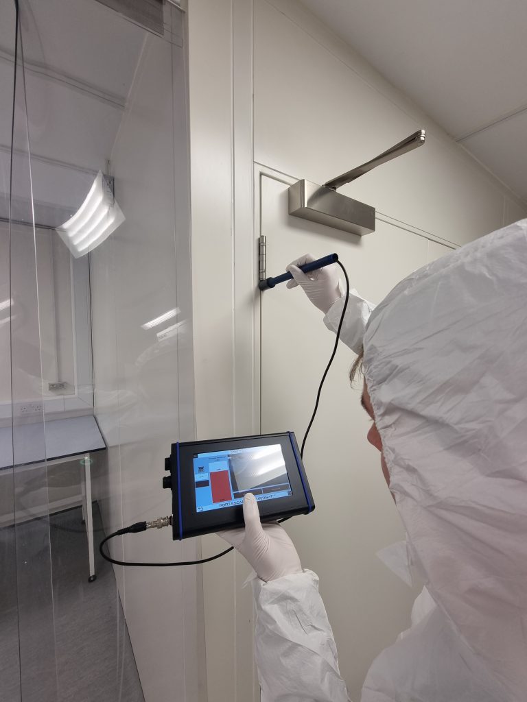
(Pic2:Air pressure test at door gap)
2.1 The air leakage test should use a special
measuring instrument that has passed the inspection, or a measuring device that
uses a metering element that meets the requirements of the current national
standard "Flow Measurement Throttling Device".
2.2 The air leakage test device can be duct type or air chamber type. The duct test device uses an orifice plate as a star counting element; the air chamber test device uses a nozzle as a star counting element.
2.3 The air pressure and air volume of the fan of the air leakage test device should be selected to be greater than the specified test pressure of the system or equipment being measured and 1.2 times the maximum allowable air leakage.
2.4 The test pressure of the air leakage test device can be adjusted by adjusting the fan speed or by controlling the opening of the throttling device. The air leakage value must be measured under the condition of maintaining a stable pressure after the system is adjusted.
2.5 The pressure difference of the air leakage test device should be measured by a micromanometer, and its minimum reading grid should not be greater than 2.0Pa.
2.6 Duct type air leakage test device:
The duct type air leakage test device consists of a fan, a connecting air duct, a pressure measuring instrument, a rectifier, a throttle and a standard orifice plate. This device uses a standard orifice plate for taking pressure, and the orifice plate B value range is 0.22~0.7 (B=d/D);
The distance from the orifice plate to the front and rear rectifiers and the straight pipe section outside the rectifier grid should meet the requirements of greater than 10 times and 5 times the diameter of the round pipe D respectively.
The connecting air ducts of this device are all smooth round pipes. The allowable deviation of the roundness within the range of 2D from the orifice plate to the upstream is 0.3%;
The sand orifice plate is connected to the air duct, and the allowable deviation of the verticality of its front end to the pipeline axis is 1°.
The allowable deviation of the concentricity between the orifice plate and the air duct is 0.015D. After the first rectifier, all connecting parts should be tight and leak-proof.
Adopt angle connection pressure standard hole flow expansion coefficient value (k=1.4)
| p2/p1 β4 | 1.0 | 0.98 | 0.96 | 0.94 | 0.92 | 0.90 | 0.85 | 0.80 | 0.75 |
| 0.08 | 1.0000 | 0.9930 | 0.9866 | 0.9803 | 0.9742 | 0.9681 | 0.9531 | 0.9381 | 0.9232 |
| 0.1 | 1.0000 | 0.992 | 0.985 | 0.9787 | 0.972 | 0.9654 | 0.9491 | 0.9328 | 0.9166 |
| 0.2 | 1.0000 | 0.9918 | 0.9843 | 0.977 | 0.969 | 0.9627 | 0.9450 | 0.928 | 0.9100 |
| 0.3 | 1.0000 | 0.991 | 0.9831 | 0.975 | 0.968 | 0.960 | 0.9410 | 0.92 | 0.9034 |
Note: 1 This table allows interpolation but not extension. 2P2/P1 is the ratio of the total pressure value after the orifice plate to the total pressure value before the orifice plate | |||||||||
2.7 Wind chamber type air leakage test device:
The wind chamber type air leakage test device consists of a fan, a connecting air duct, a pressure measuring instrument, a flow plate, a throttle, a wind chamber, a partition and a nozzle.
The test device uses a standard long-strength nozzle. The nozzle must be installed on the partition as required, and the number can be single or multiple. The center distance between the two nozzles shall not be less than 3 times the diameter of the larger nozzle throat; the distance from the center of any nozzle to the nearest side wall of the wind chamber shall not be less than 1.5 times the diameter of its nozzle throat.
The cross-sectional area of the wind chamber should not be less than the cross-sectional area of the measured air volume at a cross-sectional average velocity of less than 0.75m/h. The installation position of the flow plate (porous plate) in the wind chamber shall comply with the regulations.
The static pressure sampling interfaces at both ends of the nozzle in the wind chamber should be multiple and evenly distributed on the four walls. The distance from the static pressure sampling interface to the nozzle baffle shall not be greater than 1.5 times the minimum nozzle throat diameter. Then, connect them in parallel to form a static pressure ring and then connect them to the pressure measuring instrument.
When using this device to measure the air leakage, the flow rate through the nozzle throat should be controlled within the range of 15~35m/s.
This device requires that all connecting parts behind the nozzle baffle in the wind chamber should be tight and leak-proof.
Use the following related quantities to calculate
Multiple nozzle air volume: Q=>Qn
Single nozzle air leakage (m3/h);
Nozzle flow coefficient (0.99 for diameters above 127mm, less than 127mm);
Where ±P is the static voltage before and after the nozzle (Pa).
When testing the air leakage under negative pressure conditions of the system or equipment, the device connection should comply with regulations.
Nozzle Flow Coefficient Table
| Re | Flow coefficient Cd | Re | Flow coefficient Cd | Re | Flow coefficient Cd | Re | Flow coefficient Cd |
| 12000 | 0.950 | 40000 | 0.973 | 80000 | 0.983 | 200000 | 0.991 |
| 16000 | 0.956 | 50000 | 0.977 | 90000 | 0.984 | 250000 | 0.993 |
| 20000 | 0.961 | 60000 | 0.979 | 100000 | 0.985 | 300000 | 0.994 |
| 30000 | 0.969 | 70000 | 0.981 | 150000 | 0.989 | 350000 | 0.994 |
| Note: Temperature coefficient is not taken into account. | |||||||
3. Leakage test

(Figure 3: System leakage test)
3.1 The leakage test of air ducts and equipment in positive or negative pressure systems is divided into positive pressure test and negative pressure test. Generally, positive pressure test can be used for inspection.
3.2 System leakage test can be carried out as a whole or in sections. During the test, all openings of the tested system should be closed and there should be no leakage.
3.3 When the leakage of the tested system exceeds the requirements of the design and this specification, the leakage location should be found (listening, touching, observing, water or smoke detection can be used) and marked; after the repair is completed, retest until it is qualified.
3.4 The measured value of the leakage should generally be the actual measured value under the specified test pressure. Under special conditions, it can also be replaced by a test under a pressure close to or greater than the specified pressure.
 +86 18186671616
 Jason@cleanroomequips.com
 MENU
MENU


