+86 13638632902
 Jason@cleanroomequips.com


 MENU
MENU
Cleanroom HVAC design requires significantly more precision than typical commercial air conditioning systems. The HVAC system in a cleanroom must control temperature, manage humidity, contain particulate, and control differential pressure. Many cleanrooms have hot spots, varying humidity, and high energy costs not because the required equipment is missing, but because an accurate cleanroom heat load calculation was not made and a simple cleanroom CFM formula was used to estimate airflow.
This guide outlines the core principles of designing cleanrooms for HVAC and goes into further detail of performing heat load calculations in a step by step manner. The principles of airflow and how to size cleanrooms for appropriate CFM are also included, and most importantly outlines the differences between sensible heat and latent heat for cleanrooms and how to measure performance for eACH.
Why Cleanroom HVAC Design Is About More Than Temperature
The HVAC design for cleanrooms is far more complex than the average air conditioning system. Not only must cleanroom temperature and humidity be controlled, particulate matter must also be removed from the air and a differential pressure must be maintained. Many cleanroom owners are struggling with problems related to their HVAC systems. Not because their system does not have enough cooling capacity, but because an inaccurate cleanroom heat load calculation or the wrong cleanroom CFM formula was applied.
A good cleanroom HVAC design includes all heat and moisture sources in the room and will correspond with the degree of cleanliness required. It will also account for the climate where the cleanroom is to be located. When performing a cleanroom heat load calculation, one must make an accurate determination of sensible heat and latent heat in the room to provide stable operation in high moisture and/or high heat environments. These designs often fail due to underestimation of the outdoor air load, heat from equipment, and use of rules of thumb that determine airflow by area of room rather than by a proper engineered calculation.
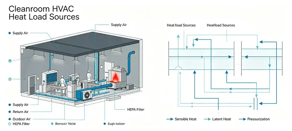
Primary heat load sources and system logic for cleanroom HVAC
Key Questions About Cleanroom HVAC Design
How to calculate cleanroom heat load?
To accurately calculate the heat load for a cleanroom, all of the sensible and latent heat in the space must be accounted for. These would include the sensible heat from equipment in the space, the sensible and latent heat from people in the space, heat from lighting, outdoor air, envelope heat transfer, and lastly any process specific heat or moisture. Each of these would need to be calculated and then added up to get the total cooling and dehumidification needs for the space.
What is the cleanroom CFM formula?
For determining cleanroom CFM values, there are three key factors that need to be satisfied. Since there is no one-size-fits-all cleanroom formula for determining CFM values (which represent required supply airflow), values need to satisfy all three constraints. Cleanliness constraints in most cases will determine the required CFM values for higher grade cleanrooms.
Sensible heat vs latent heat cleanroom
Sensible heat and latent heat are two important parameters that need to be determined and included in the design and dimensioning of cleanrooms. By varying the sensible heat, the air temperature can be altered without any change in moisture content. In contrast, latent heat is required for changes in the phase of water and affects the relative humidity in the cleanroom. Many designs underestimate the latent heat loads with resulting humidity drift, risk of condensation and below par process yield in applications such as pharmaceutical and electronics manufacturing.
Cleanroom Heat Load Calculation: Methods and Formulas
A complete cleanroom heat load calculation includes both sensible and latent heat load. The sensible heat load is made up of heat from the operation of equipment and lighting in the cleanroom as well as heat transferred through the walls and ceiling of the cleanroom. The dry heat that is given off by the occupants of the cleanroom also needs to be added to the sensible heat load. The latent heat load is comprised of the personnel respiration and perspiration as well as process evaporation and moisture brought into the cleanroom by the makeup air.
Core formulas used in HVAC design for cleanrooms include:
- Sensible heat (Qs): Qs = 1.08 × CFM × ΔT (Btu/h), where ΔT = supply-to-room temperature difference
- Latent heat (Ql): Ql = 0.68 × CFM × ΔW (Btu/h), where ΔW = humidity ratio difference (grains/lb)
- Total cooling load: Qt = Qs + Ql
- Safety factor: Final load multiplied by 1.15–1.25 to cover peak conditions and filter aging
Step-by-Step Calculation Walkthrough (Pharmaceutical Cleanroom)
Below is a full cleanroom heat load calculation for a typical ISO 7 pharmaceutical processing room to demonstrate real-world application:
- Room dimensions: 100 m² (1,076 sq ft) floor area, 3 m (9.84 ft) ceiling height → 300 m³ (10,594 cu ft) volume
- Equipment sensible load: 3 processing machines × 4 kW each = 12 kW = 40,956 Btu/h
- Personnel load (5 operators, moderate activity): 250 Btu/h sensible + 200 Btu/h latent per person → 1,250 Btu/h sensible, 1,000 Btu/h latent
- Lighting load (15 W/m²): 100 m² × 15 W = 1.5 kW = 5,120 Btu/h sensible
- Envelope conduction load: ~3,200 Btu/h sensible for standard wall/roof construction
- Outdoor air load (20% of supply air): ~8,400 Btu/h sensible, 12,800 Btu/h latent at summer design conditions
- Subtotal: 58,926 Btu/h sensible, 13,800 Btu/h latent
- With 1.2 safety factor: Total cooling capacity = ~87,270 Btu/h ≈ 7.3 tons of refrigeration
Cleanroom CFM Formula: Determining Supply Airflow
While thermal load is a key input, the cleanroom CFM formula for most facilities is driven primarily by air change rates tied to ISO classification. Designers follow a three-tier validation process to confirm airflow requirements.
Step 1 – ACH baseline calculation:
CFM = (Room Volume × Required ACH) / 60
| ISO Cleanroom Class | air changes per Hour (ACH) | Typical Industries & Applications |
|---|---|---|
| iso 5 (class 100) | 240 – 480 | Semiconductor wafer fabrication, sterile compounding, aseptic filling |
| ISO 6 (Class 1,000) | 120 – 180 | Pharmaceutical packaging, optical assembly, medical device manufacturing |
| ISO 7 (Class 10,000) | 60 – 90 | SMT electronics assembly, general medical device, compounding pharmacy |
| iso 8 (class 100,000) | 20 – 40 | Food packaging, general laboratory, plastic injection molding |
| ISO 9 | 4 – 10 | Controlled warehouse, gowning areas, buffer rooms |
ACH: 240 – 480
Use: Semiconductor fab, aseptic filling
ACH: 120 – 180
Use: Pharma packaging, optical assembly
ACH: 60 – 90
Use: SMT electronics, medical devices
ACH: 20 – 40
Use: Food packaging, general labs
ACH: 4 – 10
Use: Warehouses, gowning rooms
Step 2 – Thermal load cross-check:Check if the required air flow to remove the sensible and latent heat (of the users and equipment) equals or even exceeds the air flow required based on the ACH method. In case of a higher thermal load, then the higher air flow is required to maintain the set points.
Step 3 – Cleanliness and pressure correction: This step adjusts for the filter pressure drop, room pressurization and for the various airflow distribution losses. Jason.peng, lead engineer Deiiang™, states that typically a margin of 10–15% is added for HEPA Filtration loading over time.
The ACH requirement alone for most ISO 7 and higher grade facilities will dictate a much higher airflow than the thermal load of the space alone. In most cases standard AC sizing rules do not apply when designing HVAC for cleanrooms, because cleanliness of the space is typically the controlling factor for airflow as opposed to comfort cooling.
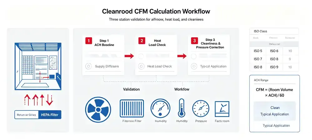
Three-step CFM validation workflow
Core Principles of HVAC Design for Cleanrooms
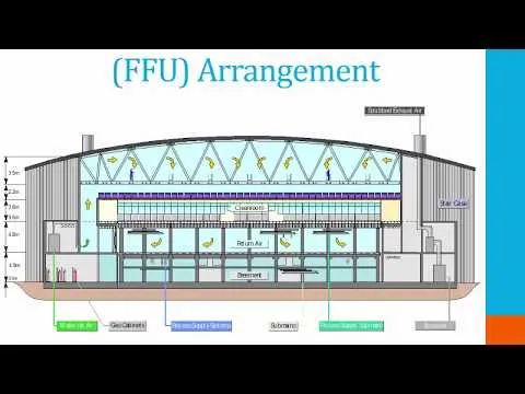
HVAC design for cleanrooms is more than just calculating the loads and the required airflow. The design has to take into account the distribution of the air, the return of the air and the different cooling options.
Airflow pattern: Unidirectional, non-unidirectional, or mixed-flow as applicable to respective Cleanliness Class and associated process layout.
Pressure gradient: Positive pressure (5–20 Pa) relative to adjacent, less-clean areas in order to avoid contamination by outside air.
Control logic: Cooling and dehumidification in two separate stages in order to control temperature and humidity as precisely as possible.
Filter matching: The HEPA/ULPA filter efficiency in combination with the face velocity is coordinated with the airflow, the room requirements and the respective cleanliness targets.
Return air design: In general return air grilles are positioned to prevent the formation of heat stratification or supply air short-circuiting.
Problems with airflow in a cleanroom more often are a result of problems with airflow distribution than with problems with CFM (air change rate) in general. More efficient distribution of return air and supply air by means of improved location of diffusers and return air grilles can already solve a number of problems.
Sensible Heat vs Latent Heat in cleanroom environments
This distinction in cleanroom loads determines the system’s capability and stability in terms of sensible and latent heat removal. The sensible heat removal is indicative of the system’s capability to maintain a set temperature, whereas the latent heat removal is indicative of the system’s capability to control the humidity.
| Parameter | Sensible Heat | Latent Heat |
|---|---|---|
| Primary effect | Air temperature change | Air moisture / humidity change |
| Main sources | Equipment, lighting, envelope conduction | Personnel, process evaporation, outdoor air |
| Design focus | Cooling capacity, supply air temperature | Dehumidification, dew point control |
| Humid climate share | 65–70% of total load | 30–35% of total load |
Effect: Air temperature change
Sources: Equipment, lighting, envelope conduction
Design focus: Cooling capacity, supply air temperature
Effect: Air moisture / humidity change
Sources: Personnel, process evaporation, outdoor air
Design focus: Dehumidification, dew point control
"90% Cleanroom Temperature & Humidity Failures are caused by inadequate ‘Latent Heat Treatment’ in design rather than by an inability to supply the required Total Cooling in first place. In many designs only the Sensible Heat has been allowed for in sizing for and dehumidification treatment under HVAC design." — Jason.peng, Lead HVAC Engineer, Deiiang™
Pharmaceutical, electronics and life science cleanrooms are highly sensitive to latent load. Even small changes in humidity can lead to product corrosion, powder agglomeration or even microbial growth. In these applications temperature control is often less of a problem than latent load control.
Local Climate & Industry Data for Accurate Sizing
Most generic cleanroom heat load calculation formulas lack localization. To provide a reliable HVAC solution for cleanrooms, regional climate data needs to be integrated into industry-specific process profiles, and relevant standards have to be met.
Key climate factors that influence the amount of outdoor air required to cool a cleanroom include the summer design dry-bulb temperature, wet-bulb temperature and annual average relative humidity. High humidity climates can produce high latent heat loads from the makeup air required to control cleanroom humidity. In some cases these can increase the total cooling requirement by as much as 30% above that required for arid cleanrooms.
In addition to the variables of equipment sensible heat, cleanrooms have different load patterns depending on the industry. For example, very high density pharmaceutical cleanrooms have high latent heat from personnel and process wetting, whereas food packaging cleanrooms would require moisture resistant components to withstand frequent washdowns. The following are relevant standards for Cleanroom Heating Ventilation and Air Conditioning (HVAC) design.
Deiiang™ Cleanroom HVAC Product Performance
Deiiang™ modular cleanroom HVAC systems can cover a full range of loads and airflow rates to meet the needs of ISO 5 to ISO 9 cleanrooms. Deiiang’s modular design allows for flexible configurations to fit specific applications, says lead product engineer Jason.peng. These units include functions of cooling, dehumidification, air filtration and supply fan in a compact unit that can be easily installed in the field.
- Airflow range: 200 to 12,000 CFM per unit, with modular cascade for larger facilities
- Temperature accuracy: ±0.3°C to ±1.0°C; humidity accuracy: ±2% RH to ±5% RH
- Filtration: MERV 8 pre-filter + H14 HEPA final filter, 99.995% efficiency at 0.3 μm
- EC variable-speed fans reduce energy use by 25–35% vs. constant-volume AC systems
Field data from Deiiang™ installations shows that systems sized using proper cleanroom heat load calculation and zoned airflow control maintain setpoint stability 40% better than single-zone constant-volume designs.
Case Study: High-Density Electronic Cleanroom
Semiconductor SMT Assembly Facility in coastal region requires ISO 7 Cleanroom for high density production at a constant temperature of 22°C (+/-1°C) and humidity of 45% (+/-5%) RH on a 24/7/365 basis. The production area is approximately 2,200 sq. ft. and contains a number of high-heat reflow ovens concentrated in one production area or zone. The uneven thermal distribution in the production area, as well as summer humidity control, presented significant problems under the original baseline design.
Deiiang™ also specified a unique cleanroom CFM formula, that of a zoned airflow strategy, or in this case of three independent thermal zones, with return grilles at low levels to under seat return of contaminated air from under ovens, a supplementary dehumidification to contend with the high humidity in summer, and variable-speed fan control based on the current load.
The temperature controlled within ±0.6°C while the humidity was controlled within ±3% RH in all areas after putting the cleanroom into operation. In the mean time, the annual energy consumption by HVAC of the cleanroom area was reduced by 19% with the estimated annual saving of US$15,000 by in turn reducing the electricity cost of the assembly area.
Common Misconceptions in Cleanroom HVAC Design
Higher CFM always means better cleanroom performance
Excessive airflow results in increased energy usage, creates noise, and most importantly can create turbulent eddies in the room that actually decrease the particle removal efficiency. So the key is to distribute the airflow in an even and balanced manner.
Temperature calculation is sufficient for cleanroom HVAC sizing
Temperature calculation is sufficient for cleanroom HVAC sizing
Omitting latent heat can result in high humidity, condensation and contamination problems. A reliable cleanroom heat load calculation includes both sensible and latent heat.
All cleanrooms follow the same sizing formulas
All cleanrooms follow the same sizing formulas
Each application will have its own specific load profile, which will determine the relative importance of thermal vs. clean-air requirements.
Equipment nameplate power equals heat load
Equipment nameplate power equals heat load
Most equipment does not operate at its name plate rating all the time and must be addressed using appropriate diversity factors and typical operating duty cycles to avoid over designing.
Higher cleanliness requires unlimited ACH increases
Higher cleanliness requires unlimited ACH increases
Adding more Air Changes delivers decreasing amounts of value beyond a point. Cleanliness of a cleanroom is determined by the Filter efficiency, Air flow distribution, and Source (material, process) control, not by increasing the fan speed.
All rooms should be sized using peak nameplate load
This “lazy engineering” method of design is prevalent in the industry today. Rather than accurately designing each zone to the appropriate maximum nameplate ampere rating and recognizing true diversity factors and respective operating duty cycles, contractors simply apply maximum nameplate power to every respective zone of a system. The result is an oversized constant-volume system operating at 30% to 40% excess capacity continuously. The resulting high operating utility cost can be reduced by as much as 18% to 25% per year by a Deiiang system that uses precision load matching to accurately follow the operating profile of each respective zone of a system.
Quick Glossary of Key Terms
- ACH (air changes per hour): Measure of how many times total room air volume is replaced per hour; a primary cleanroom airflow sizing metric.
- Sensible Heat: Thermal energy that changes air temperature without altering moisture content.
- Latent Heat: Thermal energy associated with water phase changes, affecting humidity without changing dry-bulb temperature.
- CFM (Cubic Feet per Minute): Standard volumetric airflow unit for cleanroom HVAC system specification.
- HEPA Filtration: High-efficiency particulate air filtration with minimum 99.97% removal of 0.3 μm particles, core to cleanroom air quality control.
References
- iso 14644-1:2015 — Cleanrooms and associated controlled environments
- ASHRAE 62.1 — Ventilation for Acceptable Indoor Air Quality
- ASHRAE 170 — Ventilation of Health Care Facilities
- EU GMP Annex 1 — Manufacture of Sterile Medicinal Products