+86 13638632902
 Jason@cleanroomequips.com


 MENU
MENU
iso 5 cleanrooms have very strict requirements for air cleanliness and are controlled by the HVAC system. For particle control, and for maintaining a suitable pressure differential, the HVAC system must also control for temperature and humidity.
A poorly designed HVAC system for an iso 5 cleanroom will incur excessive operating costs, increase the complexity of maintenance, and will likely fail certification. A good design, on the other hand, will function reliably and meet all the relevant regulations.
Executive Summary
- ISO 5 cleanrooms are highly filtered and require constant airflow. The airflow needs to be controlled in such a way that the particles are locked onto a specific path and there is as little turbulence as possible.
- A clean room's HVAC system can be designed with the following elements in mind: uniform supply of air, maintenance of pressure difference, T/H (temperature/humidity) control, filtration in stages, and system redundancy.
- Deiiang™ offers custom AHU solutions, precision controls, energy optimization and on-site commissioning to optimize cleanliness and operating costs.
- Deiiang™ supports projects with custom AHU solutions, with control systems for precise control, energy optimization and on-site commissioning to ACHieve the required cleanliness while also considering operating costs.
What Is ISO 5 Cleanroom and Why HVAC Matters
ISO 5 (class 100) limits to 3,520 particles ≥0.5 µm/m³ and 220 particles ≥0.3 µm/m³. ISO 5 cleanrooms are required for the production of sterile pharmaceuticals, for semiconductor photolithography, for precision optics, and for highly advanced medical devices.
A proper designed ventilation system for an ISO 5 cleanroom is the core of contamination control. Even the best architecture for a cleanroom does not help if the ventilation system is not properly designed.
Real-world applications:
- Semiconductor fabrication (wafer processing)
- Sterile injectable drug manufacturing
- Medical implant production
- Precision optical assembly
Biological research laboratories
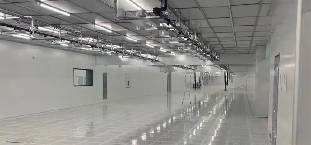
ISO 5 cleanrooms serve:
For pharmaceutical clients, ISO 5 aligns with gmp grade a. For manufacturing, the focus is on maintainability, stability, and energy control. Deiiang™ integrates these perspectives into every design.
Core HVAC Design Goals for ISO 5 Cleanrooms
An effective iso 5 cleanroom hvac design must achieve multiple interdependent objectives. These goals form the foundation of a robust system.
- Particle concentration: ISO 5 levels must be maintained at all times when the enclosure is in operation.
- Pressure differential: Positive stable pressure differential (typically 10–15 Pa) to prevent cross-contamination.
- Temperature control: Maintain ±0.5 °C or tighter for process stability.
- Humidity control: Achieve ±2% RH or better to prevent condensation and ensure prevention of static electricity.
- Airflow uniformity: Unidirectional flow to minimize turbulence and ensure no 'dead' areas in the work area.
- Operational reliability: Support 24/7/365 continuous operation with redundancy.
- Cost efficiency: lowest energy consumption per unit of clean air produced.
Design relationship: Cleanliness → Airflow/Filtering → Pressure Differential → Stability → Energy Consumption. Each element affects the others.
Cleanroom Ventilation System Design
Airflow Organization
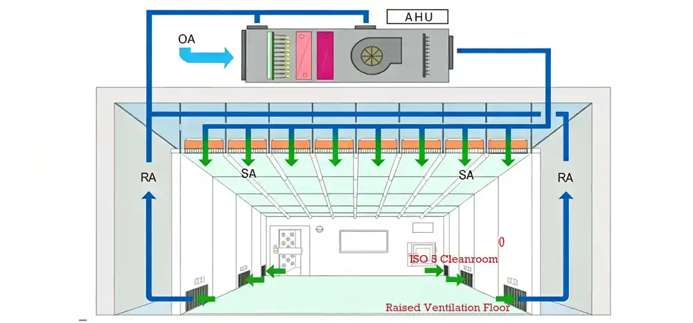
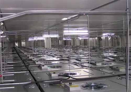
Unidirectional (laminar) airflow is typically used in ISO 5 cleanrooms. Air flows down from the ceiling HEPA/ULPA filters through the work area and then is extracted from low-level returns. This airflow pattern helps to sweep particles away from critical areas.
- Unidirectional flow: Essential for ISO 5; air velocity of 0.45 m/s ±20% is common.
- Return placement: Low-level returns on opposite walls prevent recirculation.
- Dead zone elimination: Use computational fluid dynamics (CFD) to identify and correct stagnant areas.
- High-pollution zones: Isolate with additional local exhaust or dedicated returns.
The iso 5 cleanroom ventilation system must be designed with airflow patterns that minimize turbulence and prevent particle entrapment.
air changes and Supply Logic — with Formulas
ISO 5 cleanrooms are defined by unidirectional flow, not by air changes per hour (ACH). The critical parameter is face velocity (typically 0.36–0.54 m/s) across the entire ceiling area.
Where:
- Q = supply airflow (m³/h)
- A = cleanroom cross-sectional area (m²)
- v = average face velocity (m/s)
For a 10 m² ISO 5 zone at 0.45 m/s: Q = 10 × 0.45 × 3600 = 16,200 m³/h. ACH would be ~1,620 h⁻¹ — but the velocity is the real design driver.
HEPA ceiling coverage typically ranges from 60% to 100% of the ceiling area. Higher coverage improves velocity uniformity and reduces dead zones.
Cleanroom Recovery & Dynamic Control
iso 14644-3 mandates the recovery test (100:1 decay time) — the time needed for particle concentration to drop from 100× to 1× the ISO 5 limit. Typically, this must be < 15–20 minutes.
Where \( n \) = air change rate (h⁻¹), \( C_1 \) = initial concentration, \( C_2 \) = target concentration.
For ISO 5, a well-designed system achieves recovery in ≤15 min. Deiiang™ projects consistently verify recovery < 12 min during FAT.
Dynamic control includes fast-acting VAV dampers and pressure-independent valves to maintain stability during filter loading and door operations.
The AHU is the core component of any iso 5 cleanroom air handling unit system and after being conditioned it is distributed in the cleanroom with the utmost precision and reliability.
Deiiang™ provides state-of-the-art custom AHU solutions. They have vast experience in cleanrooms and design each AHU unit to meet project specific requirements.
Pressure Differential Control & Airlock Strategy
A positive pressure of 10-15 Pa above adjacent lower grade areas will prevent contamination of clean areas by external contamination. The pressure in each area will decrease in a cascading manner from the cleanest area to the least clean area.
- Use pressure-independent control valves or VAV terminals.
- Monitor differential pressure at every critical door and pass-through.
- Compensate for door openings with fast-acting control loops.
Airlock types for ISO 5:
| Airlock Type | Pressure Pattern | Application |
|---|---|---|
| Bubble | High → Low → High (internal positive) | Protecting ISO 5 from adjacent lower-grade areas |
| Sink | Low ← High ← Low (internal negative) | Containment of hazardous materials |
| Cascade | Stepped gradient (e.g., iso 7 → ISO 5) | Standard pharma/semicon cleanroom suites |
| Type | Pattern | Use |
|---|---|---|
| Bubble | High→Low→High | Protect ISO 5 |
| Sink | Low←High←Low | Hazard containment |
| Cascade | Stepped gradient | Standard suites |
Temperature and Humidity Control
While not part of the ISO 5 definition, temperature (typically 20–22 °C) and humidity (45–55% RH) are vital for process stability, worker comfort, and static control.
- Precision cooling coils with dehumidification capacity.
- Reheat systems for tight humidity control in humid climates.
- Humidification with clean steam or ultrasonic systems.
- Fan heat gain: In recirculation systems the heat from the fan motor can add up to 2-4° C to the supply air. This must be included in the cooling load calculations to avoid under-sizing the cooling.
Air Handling Unit Selection for ISO 5
The AHU is the core component of any iso 5 cleanroom air handling unit system and after being conditioned it is distributed in the cleanroom with the utmost precision and reliability.
Deiiang™ provides state-of-the-art custom AHU solutions. They have vast experience in cleanrooms and design each AHU unit to meet project specific requirements.
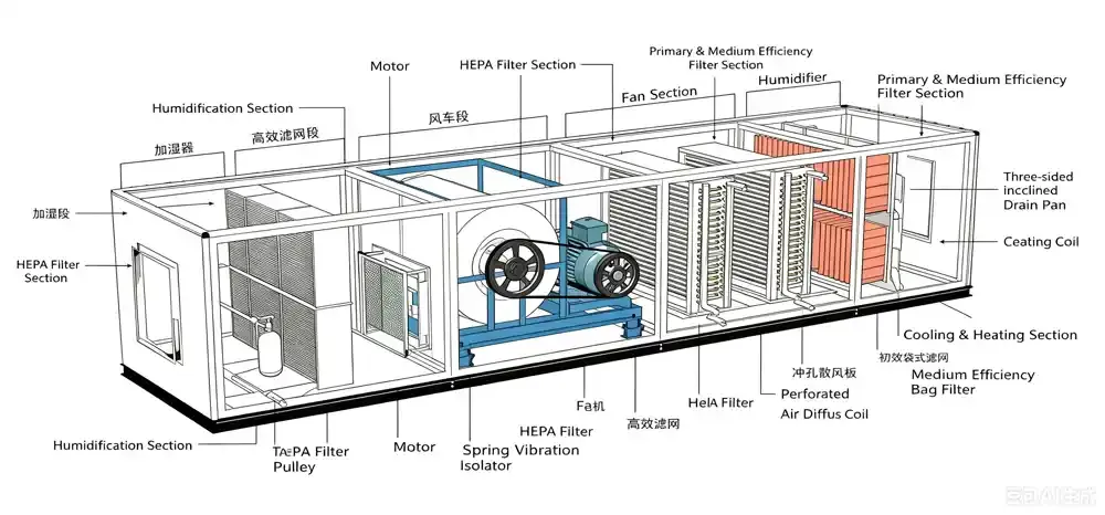
Key AHU Components
- Fan section: Plug-fan or belt-driven centrifugal, with VFD for speed control.
- Pre-filter (G4/F5): Removes coarse particles to protect downstream filters.
- Cooling coil: DX or chilled water, sized for peak sensible and latent loads.
- Heating coil: Hot water or electric for winter heating and reheat.
- Humidification: Clean steam or ultrasonic, with 0.5 °C control precision.
- Final filter section: HEPA/ULPA with airtight frame.
- Control system: PLC-based with Modbus/BACnet integration.
AHU Selection Criteria
- Airflow range: 3,000–60,000 m³/h or higher, matched to cleanroom volume and velocity.
- Static pressure: 800–1,500 Pa typical, with margin for filter loading.
- Temperature control: ±0.3–0.5 °C precision.
- Humidity control: ±1–2% RH precision.
- Filter staging: G4 + F7/F9 + H13/H14.
- Redundancy: N+1 fan/filter configuration for critical applications.
- Energy efficiency: EC fans and inverter compressors reduce part-load energy by 20–35%.
Deiiang™ specification example: Custom AHU with 18,000 m³/h airflow, 1,200 Pa static pressure, ±0.3 °C temperature control, and integrated H13 HEPA filtration — designed by Jason.peng for a semiconductor cleanroom project.
Performance Comparison: AHU Types
| Feature | Standard AHU | Deiiang™ Custom AHU |
|---|---|---|
| Airflow range (m³/h) | 5,000–40,000 | 3,000–60,000+ |
| Static pressure (Pa) | 600–1,200 | 800–1,500+ |
| Temp. precision (°C) | ±0.5 | ±0.3 |
| Humidity precision (% RH) | ±2 | ±1 |
| Filter staging | G4+F7+H13 | G4+F7+F9+H13/H14 |
| Energy saving (vs. fixed-speed) | 15–20% | 25–35% |
| Redundancy | Optional | N+1 standard |
| Feature | Std AHU | Deiiang™ |
|---|---|---|
| Airflow (m³/h) | 5k–40k | 3k–60k+ |
| Static pressure (Pa) | 600–1200 | 800–1500+ |
| Temp. precision (°C) | ±0.5 | ±0.3 |
| Humidity precision (%RH) | ±2 | ±1 |
| Filter staging | G4+F7+H13 | G4+F7+F9+H13/H14 |
| Energy saving | 15–20% | 25–35% |
| Redundancy | Optional | N+1 |
Filtration Strategy: HEPA vs ULPA
Filtration is the most critical element of any iso 5 cleanroom air handling unit system. The final filter stage determines the actual cleanliness level achieved.
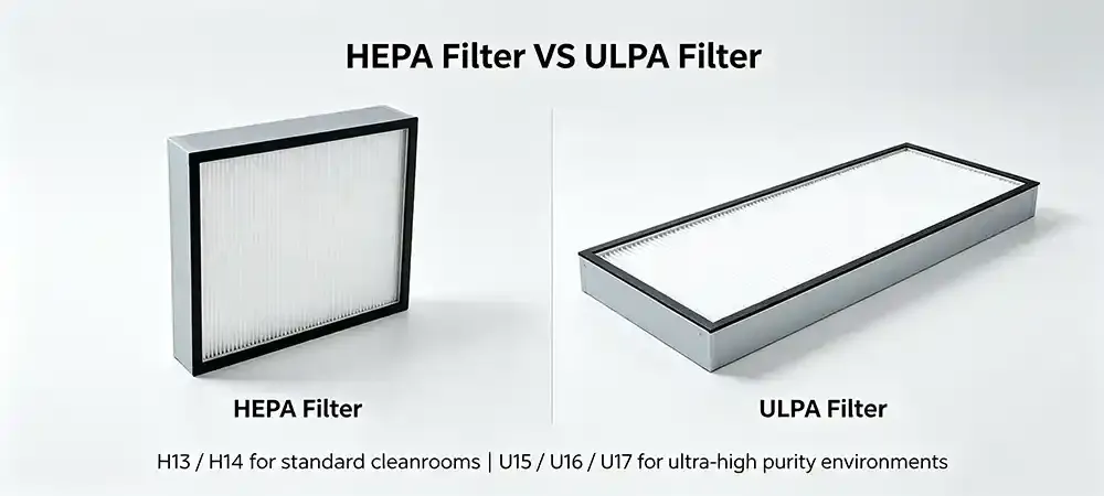
HEPA Filters (H13/H14)
- H13: ≥99.95% efficiency at MPPS (≥99.97% at 0.3 µm).
- H14: ≥99.995% efficiency at MPPS.
- Sufficient for most ISO 5 pharmaceutical and medical applications.
- Lower pressure drop than ULPA, reducing fan energy.
ULPA Filters (U15–U17)
- U15: ≥99.9995% at 0.12 µm.
- U16: ≥99.99995% at 0.12 µm.
- U17: ≥99.999995% at 0.12 µm.
- Required for semiconductor sub-10nm processes and advanced research.
- Higher pressure drop; must be balanced with system static capability.
Filter Selection Matrix
| Filter Grade | Efficiency (0.3µm) | Typical Application | Pressure Drop (Pa) | Cost Index |
|---|---|---|---|---|
| H13 | ≥99.97% | Pharma, medical devices, general ISO 5 | 180–220 | 1.0 |
| H14 | ≥99.995% | Sterile filling, advanced pharma | 200–250 | 1.3 |
| U15 | ≥99.9995% | Semiconductor (sub-10nm), research | 240–300 | 1.8 |
| U16 | ≥99.99995% | Semiconductor (sub-7nm), nanotech | 280–350 | 2.5 |
| U17 | ≥99.999995% | Atom-scale research, extreme clean | 320–400 | 3.5 |
| Grade | Efficiency | Application | ΔP (Pa) |
|---|---|---|---|
| H13 | 99.97% | Pharma, general ISO 5 | 180–220 |
| H14 | 99.995% | Sterile filling | 200–250 |
| U15 | 99.9995% | Semiconductor | 240–300 |
| U16 | 99.99995% | Sub-7nm fab | 280–350 |
| U17 | 99.999995% | Atom-scale research | 320–400 |
Deiiang™ offers both HEPA and ULPA filter housings with airtight frames, certified to EN1822 and IEST-RP-CC034. The Jason.peng design team can recommend the optimal filter grade based on your process requirements and energy budget.
4 Common Pitfalls in ISO 5 Cleanroom HVAC Design
Avoid these costly mistakes with real‑world insight from Deiiang™ field engineers.
Picking the ULPA for every ISO 5 project blind. For non-sub-10nm semiconductor and for pharma, using U15/U16 filters increases the initial pressure by 40% and therefore also doubles the fan energy required. For most of the pharmaceutical ISO 5 applications, H14 + high-efficiency pre-filtration is the cost-effective sweet spot.
Instead of gasket-sealed HEPA frames use fluid/gel-seal frames. Gasket seals deteriorate with vibration and cause micro-leaks which can lead to high particle counts. ISO 5 cleanrooms need liquid-gel seal (fluid seal) ceiling grids for long-term clean-room integrity.
Omitting the fan heat gain. For recirculation systems the heat generated by the fan motors for the supply air can add up to 2-4°C. Omitting this sensible heat load will result in undersized cooling coils and in humidity drift. The fan heat must be included in the cooling load calculation.
Skipping on‑site DOP/PAO leak testing. Many systems pass factory tests but fail on‑site due to installation damage. Deiiang™ enforces 100% on‑site PAO testing with a first‑pass rate of 100% in our recent projects.
Energy Efficiency Optimization
One of the key issues in the design of HVAC for iso 5 cleanrooms is the need to balance cleanliness with energy consumption. A 20% reduction in energy usage can translate into hundreds of thousands of dollars in annual savings for a large facility.
Energy-Saving Strategies
- Variable Frequency Drives (VFDs): VFDs control variable speed of fan to reduce energy usage up to 40% while running partial load.
- Zone-based airflow control: Allows for specific airflow rates in individual areas and reduces excess airflow.
- High-efficiency filters: Low-pressure-drop filters reduce fan energy.
- Heat recovery: From exhaust air by preheating of supply fresh air by means of an enthalpy wheel.
- Intelligent controls: PID loops, demand-based ventilation, and real-time monitoring.
- DC inverter compressors: By constantly changing the compressor's capacity in a DX system, savings of up to 35% can be achieved compared to a fixed-speed compressor.
A 10,000 m² semiconductor cleanroom was optimized for the Iso 5 ventilation system, utilizing VFDs and heat recovery. Estimated annual energy savings and payback would be approximately 22–28% and less than 24 months respectively.
EC Plug Fans Used in Retrofit with Modbus Group Control to Save $48,000/Year in a 10,000m² Semiconductor Cleanroom — 31.4% Savings over AC Fixed-Speed Fan Used Previously.
ISO 5 Cleanroom Airflow, HEPA & Energy Estimator
Enter room dimensions, face velocity, and system parameters to estimate airflow, HEPA quantity, fan power, cooling load, and total AHU input power.
Deiiang™ Case Study: Semiconductor ISO 5 Cleanroom
Project: Advanced semiconductor photolithography cleanroom
Location: Southeast Asia (high ambient temperature and humidity)
Cleanroom grade: ISO 5 (Class 100), 800 m² production area
Process: 300 mm wafer handling with sub-10nm line widths
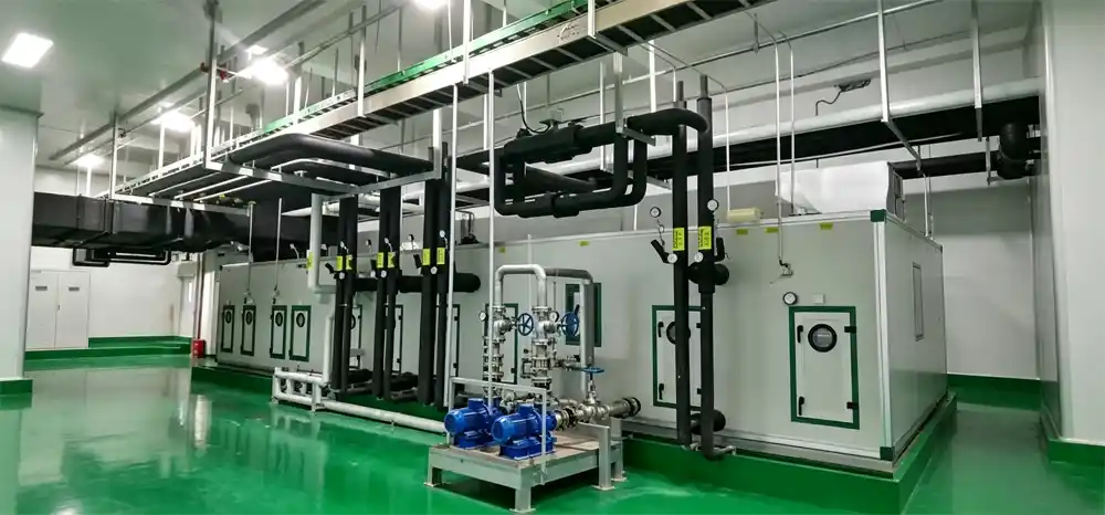
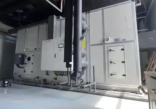
Deiiang™ AHU installation
Project Challenges
- Stringent particle control: ≤3,520 particles ≥0.5 µm/m³ continuous.
- Temperature stability: ±0.3 °C required for photolithography tools.
- Humidity control: 45±1% RH to prevent static discharge and resist drift.
- Limited mechanical room space; AHU footprint constrained.
- High ambient dew point (28°C) necessitating deep dehumidification.
- 24/7 operation with zero downtime tolerance.
Deiiang™ Solution
- Custom AHU with 42,000 m³/h airflow, 1,450 Pa static pressure and ±0.3 °C / ±1% RH control.
- Filter staging for the new AHU: G4 pre-filter / F7 bag filter / F9 bag filter / H14 HEPA terminal filter.
- DX cooling coil with inverter scroll compressor.
- The EC plug fans run with VFD to minimize energy consumption by 32% compared with the fixed speed solution.
- This can be integrated using a PLC with Modbus output to the BMS to log a 14 day trend.
- N+1 fan redundancy, and dual cooling circuits for fail-safe operation.
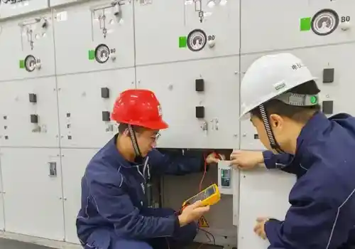
- On-site commissioning performed by Jason.peng and the Deiiang engineering team to verify performance.
- Pre-installation cleaning: Before installation of the ductwork and the AHU units all surfaces have been cleaned to Class 0 standards in order to prevent contamination with debris from the construction site.
Results
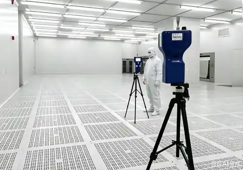
- Particle counts consistently below ISO 5 limits (measured via 0.3 µm and 0.5 µm channels).
- Temperature maintained within ±0.25 °C of setpoint over 12 months.
- Humidity stable at 45±0.8% RH across all seasons.
- Total energy consumption reduced by 26% compared with the original fixed-speed system.
- Filter life extended by 18% due to optimized pre-filtration and low-pressure-drop final filters.
- System passed iso 14644-1 certification on first attempt.
- On‑site PAO leak test: 100% first‑pass rate.
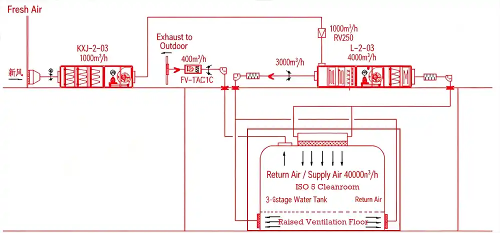
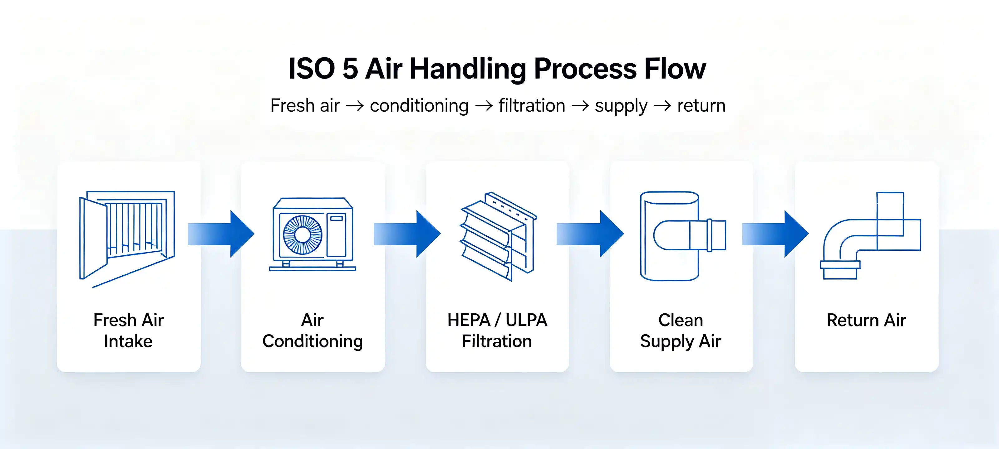
ISO 5 Air Handling Process Flow
Detailed Technical Specifications (Toggle)
- Airflow: 3,000 – 60,000+ m³/h
- Static pressure: up to 1,800 Pa
- Temp. control: ±0.3°C
- Humidity control: ±1% RH
- Filter staging: G4+F7+F9+H13/H14
- Fan types: EC plug fans with VFD
- Refrigerant: R410A inverter scroll
- Certifications: Eurovent, AHRI, CE
- H13, H14, U15, U16, U17
- Frame: anodized aluminum, stainless steel
- Seal: gel/fluid seal or gasket
- Test: DOP/PAO scanning, MPPS efficiency
- Standards: EN1822, IEST-RP-CC034
Frequently Asked Questions
What HVAC system is best for ISO 5 cleanrooms?
Is HEPA enough for ISO 5 cleanroom design?
How do you maintain pressure differential in a cleanroom?
What is the role of an air handling unit in ISO 5?
How can ISO 5 cleanrooms improve energy efficiency?
What is recovery time and why does it matter?
This measure characterizes the return time of a cleanroom to an ISO 5 classification after having been contaminated. Recovery time (100:1 decay) typically has to be less than 20 min according to ISO 14644-3. The Deiiang™ systems, however, return within less than 12 min. Thus, they can be recovered quickly from any kind of disturbance.
Conclusion: Integrated Design for ISO 5 Success
Exceptional iso 5 cleanroom HVAC design is not a sum of individual technologies. Air handling, filtration, airflow distribution, pressure and energy are integrated to form a working, reliable whole.
We can help with projects requiring the highest standards of cleanliness, stability and long-term cost effectiveness by working with experienced partners who have real engineering capability.
Ready to design your ISO 5 cleanroom HVAC system?
Get customized AHU solutions, filter selection, and energy optimization from Deiiang™.
Contact Deiiang™ for a consultation | Request AHU selection guidance | Project inquiryReferences
- iso 14644-1:2015 — Cleanrooms and associated controlled environments, Part 1: Classification of air cleanliness
- ASHRAE Handbook — HVAC Applications, Chapter 18: Clean Spaces
- IEST-RP-CC034 — HEPA and ULPA Filter Leak Test Standards
- EU GMP Annex 1 (2022) — Manufacture of Sterile Medicinal Products
- US DOE — Energy Design Guides for Cleanrooms
Article prepared by the Deiiang™ technical team. Lead engineer: Jason.peng. All performance data based on validated project outcomes and industry standards.