+86 13638632902
 Jason@cleanroomequips.com


 MENU

Indeed, you can utilize a filter with a higher MERV rating in your HVAC system; however, there are three essential criteria that must be fulfilled first. So the question "can I use a higher MERV filter in this system?" has a conditional answer, never an automatic one. The first one is that the equipment literature must allow it to be utilized. Secondly, the filter must fit properly and seal in the rack.
Finally, all the post-installation measurements must conform to the airflow and pressure requirements of the HVAC system. It is important to note that MERV alone does not dictate pressure drop; it really depends on the filter's design, media area, and operating airflow.
Before you ask can I use a higher MERV filter, MERV rating compatibility has to be confirmed against the equipment documentation rather than a generic chart.
If any one of the above criteria is not fulfilled, you should utilize the furnace filter MERV rating that has been approved for it or seek professional assistance in order to ascertain the same.

What a higher MERV rating does—and does not—mean
A higher MERV rating means that the filter was able to capture more particles according to ASHRAE 52.2 [1], A documented higher MERV filter HVAC change rests on measurement rather than on this distinction alone. but it does not necessarily mean that all of the particles will be captured during the entire life of the filter.
For instance, there could be two different filters with the same MERV rating, but differing pressure drop/backpressure curves due to differences in pleating configuration, filter design, and media area. That is why MERV rating compatibility cannot be judged from the number alone.
Furthermore, not only does MERV not equal HEPA, but MERV filters cannot be classified as HEPA under ISO 16890's ePM1, ePM2.5, and ePM10 systems. EN 779 has been retired and is no longer applicable.
Table 1: Comparative MERV Ratings
| MERV Rating | Particle Size Range (ASHRAE 52.2 E1-E3 bins) | Example Application | Disadvantages |
|---|---|---|---|
| MERV 8 | E2: 1-3 µm; E3: 3-10 µm | General Commercial Buildings | Limited Capture of Fine Particles |
| MERV 11 | E1: 0.3-1 µm; E2 & E3 higher | Basically Commercial Filtration | Higher Resistance than MERV 8 |
| MERV 13 | E1 ≥ 50%, E2 ≥ 85%, and E3 ≥ 90% | Some Medical & Pharmaceutical Pre-HEPA | Not a HEPA Equivalent |
| MERV 14-16 | higher E1 efficiencies | High-efficiency HVAC air filters | Requires Verified Fan Capacity |
| MERV Rating | Particle Size Range | Example Application |
|---|---|---|
| MERV 8 | E2: 1-3 µm; E3: 3-10 µm | General Commercial Buildings |
| MERV 11 | E1: 0.3-1 µm; E2 & E3 higher | Basically Commercial Filtration |
| MERV 13 | E1 ≥ 50%, E2 ≥ 85%, and E3 ≥ 90% | Some Medical & Pharmaceutical Pre-HEPA |
| MERV 14-16 | higher E1 efficiencies | High-efficiency HVAC air filters |
Understand what MERV measures
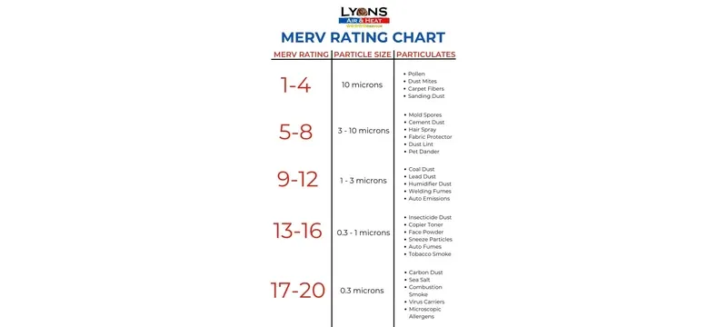
MERV stands for the ability of a filter to capture particles in twelve different size ranges based on ASHRAE 52.2. The E1 range includes particles of 0.3-1 µm, the E2 includes particles of 1-3 µm, and E3 has particles of 3-10 µm. Thus, a filter rated at MERV 13 must ACHieve at least 50% efficiency under the E1 range, 85% in the E2 range, and 90% in the E3 range of particles.
The chart above illustrates that particles captured in the MERV ratings start at large size dust particles with the lower MERV ratings, and achieve the smaller size sub-micronic sized particles with higher MERV ratings. This provides a basis for matching the efficiency curve of a filter to the contaminants of concern as different than just accepting what is presented by the MERV rating alone.
It is important to note that the test does not verify installed performance because there are issues with gaps, size, or fan. The method of using twelve bins results in an efficiency curve based on an overall analysis of the filter system.
A filter can have various efficiencies throughout all the bins therefore MERV rating compatibility will depend on comparing the efficient curve obtained to the effective contaminant that must be eliminated.
Separate MERV ratings from HEPA classifications
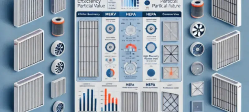
Filters that are rated based on MERV use different forms of testing than HEPA. The MERV rating is based on ASHRAE 52.2 meanwhile HEPA is classified according to EN 1822 or ISO 29463.
This shows that MERV, EN 1822, and ISO 29463 are all classified according to different methods of testing. You are advised to ask for the specific type of test that was performed prior to making the assumption that two filters are compatible.
According to the Deiiang catalogue, the efficiency of the combined high-efficiency filter H13 rated at 99.97 to 99.99% in the 0.3 µm range is based solely on catalogue data. EN 1822 H13 classification must be equal to or greater than 99.95% at the MPPS point and H14 filter must meet this requirement at the rate of equal to or above 99.995%.
Check HVAC compatibility before upgrading
Checking MERV rating compatibility begins with referring to the equipment manual. You should locate the furnace or air-handler manual to confirm the pressure drops as well as the filter types that are approved for operation.
Checklist for acquiring a higher MERV filter:
Table 2: Compatibility tests
| Criteria | Evidence needed | Pass condition | Failure remedy |
|---|---|---|---|
| Manual | Permitted MERV and/or pressure threshold | Filter type remains within threshold | Retain allowed type |
| Measurements | Filter rack and gasket measurements | Filter dimensions are appropriate for seal | Place order for required size |
| Fan operating point | Fan curve and results regarding total external static pressure | Pressure drop from the filter does not exceed the established threshold | Reduce MERV levels or examine fan |
| Filter path | Inspection of coils, fans, and ducts | No blockages or bypassing | Remediate before proceeding with MERV increases |
| Criteria | Pass condition | Failure remedy |
|---|---|---|
| Manual | Filter type remains within threshold | Retain allowed type |
| Measurements | Filter dimensions are appropriate for seal | Place order for required size |
| Fan operating point | Pressure drop from the filter does not exceed the established threshold | Reduce MERV levels or examine fan |
| Filter path | No blockages or bypassing | Remediate before proceeding with MERV increases |
Find the equipment’s permitted furnace filter MERV rating
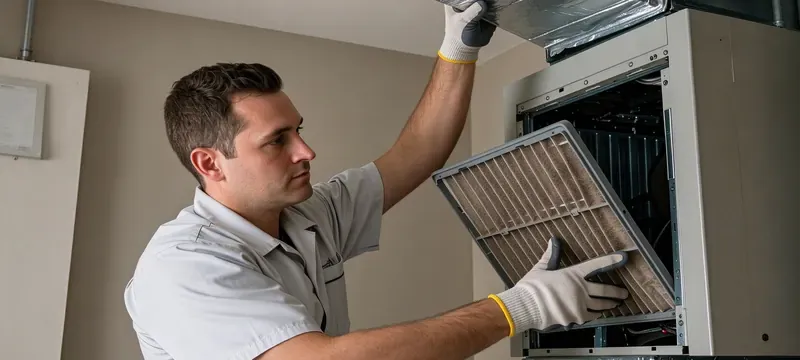
The furnace filter MERV rating is indicated in the installation manual, not in a general compatibility chart. Look for the portion on filters and note maximum MERV values, limits regarding initial resistance levels, and ranges for final resistance levels.
If no manual can be found, consult the equipment manufacturer, giving the model number and serial number of the piece. In the absence of limits, do not presume that lack of information indicates that MERV levels are approved.
This decision guide provides the process from the equipment manual and subsequent verification of pressure limits, through selection of the final filter and indicates when a filter configuration is either approved, in need of additional testing, or is deemed unacceptable. It is also the practical route by which the general question "can I use a higher MERV filter" becomes a site-specific answer. It clarifies that written filter limits must be retrieved before the installation of any higher-MERV filter.
The rack measure, as well as the kind of the gasket, should be recorded. Both affect MERV rating compatibility as much as the filter grade does. A filter that has a dimension that is less than 6 mm has a bypass method, which results in air flowing unfiltered around the filtering material.
So, Deiiang recommends confirming the exact measurements before installing any high-efficiency filters, as fitting perfectly is part of the filtration system process.
Inspect the complete filter path
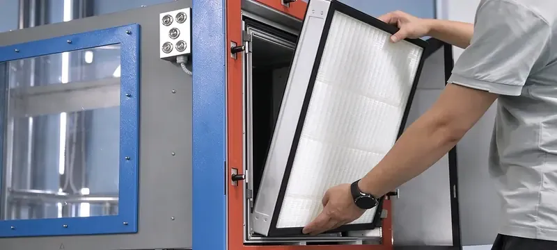
The filter only works if air passes through it completely. HVAC filter airflow that bypasses the media does no filtering at all. Start by checking the rack to see if there are any bent rails, missing gaskets, or any gaps present in the frame.
The coil should be evaluated for dust buildup and the fan must be functioning with the correct speed and direction. Having dust buildup in the coil or an improperly working fan will lead to falsely attributing low airflow issues to the higher-MERV type of filter.
This cross-section will show the rack, seals, evaporator coils, fans, and ducts. This will allow the field inspectors to identify any blockage and bypass locations throughout the filter process.
Hence, it supports the rationale that the diagnosis should start with airflow restrictions along the path before linking low flows to the filter itself.
It is also helpful to look for any return-air restriction. If the return air grill is undersized or blocked, the addition of a higher-MERV filter must have been increased static pressure throughout the system. Hence, fix the blockage before continuing further with the installation process.
Protect HVAC filter airflow and system performance

A filter that has a greater MERV number will generally present greater resistance as compared to a filter of smaller MERV number having the same size. The MERV filter pressure drop therefore follows the design, not the number alone. Such resistance warps the airflow if the fan does not have any spare capacity.
The following checklist can be used to troubleshoot before blaming the filter:
- Condition 1: Low airflow with clean filter. Action: Check fan speed setting and duct restrictions, in that order.
- Condition 2: Low airflow with dirty filter. Action: Determine pressure drop and replace the filter.
- Condition 3: Airflow not uniform across filter face. Action: Reseat or replace gasket.
- Condition 4: High TESP. Action: Check all pressure drops starting with the greatest restriction.
Understand MERV filter pressure drop
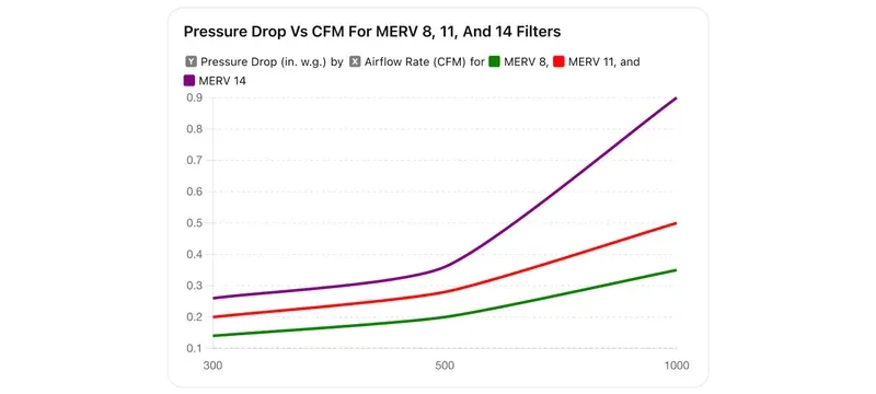
MERV filter pressure drop means the resistance to the airflow at a given flow rate. Evaluate the resistance of a clean filter at actual flow in the system, rather than at a nominal test point.
The figure illustrates the drop in pressure experienced at various rates of airflow in the case of specific Deiiang catalogue filters. This supports the argument that the filter pressure drop at the designed airflow of the system should be compared directly to the allowable external static pressure of the equipment, rather than making any inferences from using a different size or model.
Information about the Combined Efficiency Filter as per Deiiang catalogue indicates initial resistance of ≤200 Pa for H13 and ≤220 Pa for H14 maintained at respective flow rates. That is a different quantity from the MERV filter pressure drop of a panel filter at the same airflow. The figures represent catalogue information pertaining to the EN 1822 H13 and H14 models, and are not indicative of pressure drop of the MERV filter.
Static resistance is determined with a clean filter while loaded resistance increases as dust builds up on the filter. As noted by Deiiang, the final resistance for a number of these H13/H14 filters should be in the range of 400–600 Pa.
Therefore, in order for the fan to operate properly, it must always overcome the MERV filter pressure drop at its final resistance in order to evaluate air flow rates properly.
Measure airflow and confirm operating limits
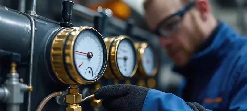
Before installing a higher-MERV filter, record the TESP and pressure drop across the filter. HVAC filter airflow and pressure together show whether the system still has capacity to spare. TESP is calculated by placing a probe in the return plenum and one in the supply plenum then taking a reading from the two. Filter pressure drop is read across the filter itself.
This workflow shows how the baseline TESP and filter pressure drops work together to allow measurement of the air flow rates for post-installation inspection.
The speed of the fan, filter type, and other operating conditions such as outdoor and return air temperatures should be recorded before any action is taken. HVAC filter airflow is judged against those recorded conditions, not against a laboratory figure. Repeat this procedure again following the installation of the new filter to ensure compatibility. A trained HVAC professional should conduct all readings utilizing a properly calibrated manometer and air flow measuring device.
Evaluate energy use, comfort, and maintenance effects
HVAC filter energy use will depend on multiple factors including the resistance of the filters, the control of the fans, the type of loading, as well as the operating hours. The use of filters with a higher MERV rating will likely increase the energy consumed by the fans as they may have to work harder so as to make the same amount of air flow through the filter.
The size of the increase in HVAC filter energy use also depends on the type of fan that is being used. The fan with variable speed control would adjust its speed and energy consumption differently compared to a fan with constant speed.
For instance, the power being used by the air would be the pressure rise multiplied by the volume flow. If we imagine that the filter increases the pressure by 50 Pa, and the fan can move 1,000 m³/h, then the extra power from air would be approximately 50 Pa x 1,000 m³/h / 3600 = 14 W before accounting for the efficiency of the fan.
If the efficiency of the fan is, say 60%, the increase in input is approximately 23 W, which translates to roughly 92 kWh of energy over a period of 4000 hours.
Estimate the effect on HVAC filter energy use
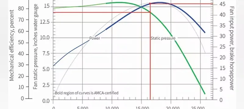
This involves use of measured pressure and fan data in order to estimate HVAC filter energy use. The same measurement discipline applies to high-efficiency HVAC air filters, which have a different resistance profile. It is important to be clear about the assumptions being made regarding the airflow, pressure rise, fan efficiency, and operating hours.
Make certain to ensure that the two periods being used for the comparison are equivalent in terms of the season and occupancy schedule being utilized. Do not make unsupported savings claims that are promoted by filter marketing.
The diagram here provides an example of an energy estimation pathway showing how one can determine HVAC filter energy use through variable pressure rise and airflow in a given period of time. It also demonstrates that one should not use catalog values and rather rely on field measurements when estimating energy consumption.
Deiiang catalog data can provide initial resistances, but field data gives the pressure rise of the installed filter. Constant-speed fans react differently to resistance compared to variable-speed fans. Changes in the airflow also change the filter's operating point. Use the field pressure to determine the fan control type for any estimation.
Set inspection and replacement triggers
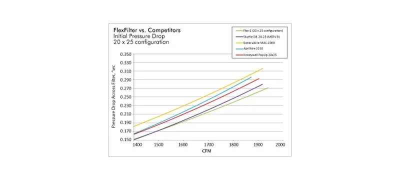
According to the trend in the differential pressure change of the filter, rising differential pressure indicates that the filter is loaded. A filter needs to be checked for media failure, frame damage, and seal condition. The replacement limit should be applicable to the specific filter and system rather than generalized for all filters.
The flow proceeds from installation checks to differential pressure trending to replacement, with inspection points at each step for verification purposes. The replacement of filters should be determined based on measured pressure and equipment limits rather than following a timed interval.
Example log of maintenance:
| Date | Filter model | Differential pressure (Pa) | Airflow (m³/h) | Action |
|---|---|---|---|---|
| 2026-01-15 | Deiiang H14 592×592×292 | 220 | 2,480 | Installed |
| 2026-04-15 | Deiiang H14 592×592×292 | 310 | 2,450 | Inspect |
| 2026-07-15 | Deiiang H14 592×592×292 | 460 | 2,410 | replace |
| Date | Filter model | Action |
|---|---|---|
| 2026-01-15 | Deiiang H14 592×592×292 | Installed |
| 2026-04-15 | Deiiang H14 592×592×292 | Inspect |
| 2026-07-15 | Deiiang H14 592×592×292 | replace |
Choose a filter strategy for the application
Not every application would require the same filtration. High-efficiency HVAC air filters belong in the second group, not the first. For example, commercial offices would require MERV 8-11 filters, but some pharmaceutical and medical applications would need MERV 11-13 pre-HEPA filters.
These examples of processing filter types do not provide the basis for an application, as other criteria would govern selection including applicable codes, risk analysis, airflow, and equipment limits. MERV rating compatibility is confirmed against those criteria, not against a marketing chart.
High-efficiency HVAC air filters and cleanroom filters have different functions. The primary purposes of high-efficiency HVAC air filters are to enhance air quality in buildings, whereas cleanroom air filter selection is based on the classification of the cleanroom and the process applied. It is not permissible to employ a MERV filter as a final filter in the iso 6 cleanroom.
Table 3: Illustrative filtration strategies (verify by local code and equipment limitations)
| Industry (example) | Filtration purpose | Requirement (for filtration) | Evidence needed | Illustrative option |
|---|---|---|---|---|
| Office | Removal of dirt | Standard fan capability | Manual-approved MERV | MERV 8–11 |
| Hospital | Removal of minute particulate and bacteria | High static pressure | Fan curve/air volume testing done | MERV 11–13 plus HEPA |
| Pharmaceutical cleanroom | iso 6 particle count | Limited plenum space | iso 14644-1 classification and filter test report | Pre-filter and H14 final use |
| Electronics cleanroom | Sub-micron particles | N/A | Verification via EN 1822 filter testing | U15–U17 |
| Industry (example) | Filtration purpose | Illustrative option |
|---|---|---|
| Office | Removal of dirt | MERV 8–11 |
| Hospital | Removal of minute particulate and bacteria | MERV 11–13 plus HEPA |
| Pharmaceutical cleanroom | ISO 6 particle count | Pre-filter and H14 final use |
| Electronics cleanroom | Sub-micron particles | U15–U17 |
Match filtration to building and process risk
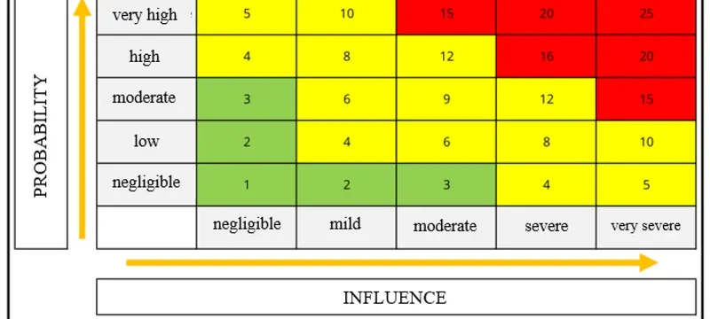
Evaluate occupancy, processes creating contamination, and equipment needed downstream. A pre-filter removes the larger particles thus prolongs the life of the final filter. The final filter corresponds to efficiency requirements.
Deiiang offers F5–F9 bag style filters as pre-filters with standard grades of F7 and F8 before HEPA. While F7 is recognized as EN 779, the applicable ISO 16890 ePM should be referred to.
This matrix correlates space risk categories with filtration stages and verification evidence required for each stage. This confirms that it is appropriate to select a level of filtration that corresponds to a specific risk assessment by validated and appropriate standards rather than attempting to model filtration grades based solely on what is found on the label of a filter in the marketplace.
For cleanrooms where there is significant particle contamination in the space, Deiiang utilized F7 prefiltration followed by low profile H14 final filtration. Cleanroom air filter selection follows the risk of the space, not a preference for a brand or a grade. The F7 prefilter reduced the load to the H14 stage, while the final filter kept the particle counts at the required level. This information pertains to a project-specific situation and cannot be universally applied.
Apply cleanroom standards to the final filtration stage
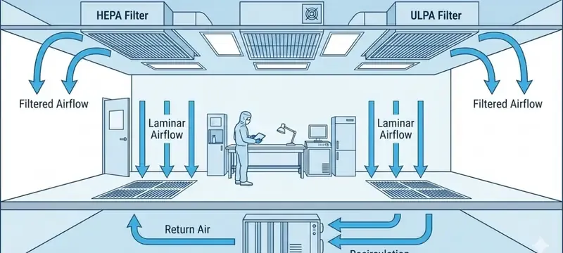
Cleanroom performance follows ISO 14644-1 for classification and iso 14644-3 for test methodologies. Cleanroom air filter selection uses those same two standards as its frame of reference. iso 14644-1 categorizes the cleanliness of the cleanroom air based on particle counts, without stating a specific filter grade requirement. ISO 14644-3 contains the methodologies. Filter grade and cleanroom classifications are separate claims.
The diagram here illustrates the process of cleanroom classification as per ISO 14644-1, filter testing using EN 1822 or ISO 29463, and filter integrity verification utilizing either IEST-RP-CC001 or ISO 14644-3.
IEST-RP-CC001.7 (2022) discusses HEPA and ULPA filter levels and provides guidance for broker agreements between vendors and customers. The methodology for DOP testing in HEPA filters is described in MIL-STD-282 Method 102.8. The DOP Integrated filters from Deiiang have been designed with a DOP testing valve for verifying filter integrity.
Implement and verify a filter upgrade
A controlled upgrade process consists of an approval process, installation, baseline measurements included, and post-installation verification. Taken in order, these steps turn the general question "can I use a higher MERV filter" into a documented yes or no. To begin with, confirm the equipment limits and the specific filter size. Ensure that the filter is installed with sealed edges and no bypass. Subsequently, take measurements of the airflow and pressure drop under the same parameters as in the baseline readings.
Field protocol numbered:
- Obtain the appropriate consent from the equipment owner/engineer for the size and classification of the filter.
- Record the baseline TESP (Pa), filter pressure drop (Pa), fan speed (RPM or setting), and airflow rate (m³/h).
- Install a brand new filter with new seals on edges.
- Measure the TESP, the filter pressure drop, and airflow soon after the installation has been completed.
- Compare your readings with the equipment limits; pass if filter pressure drop at specific airflow is within the TESP limits set by the equipment manufacturer.
- Keep your readings documented and arrange for another inspection after the initial loading of the filter.
Follow a controlled change and commissioning workflow
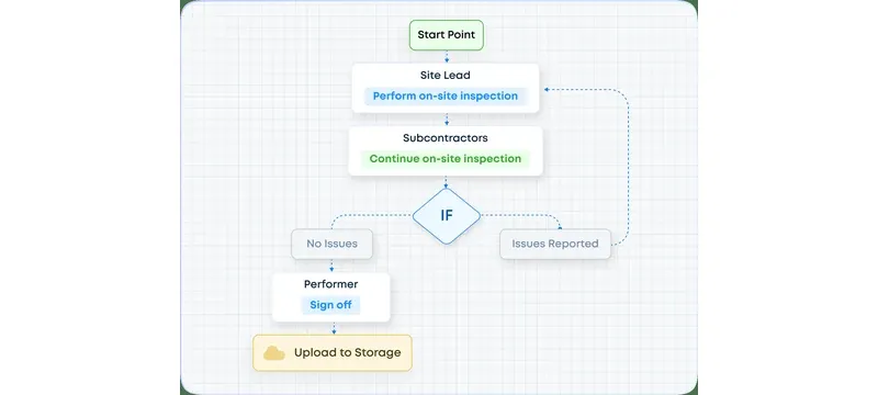
Ensure you have the equipment limits approved prior to ordering, select the filter size exactly, and confirm the type of gasket you will need. Install the filter and capture the baseline and post-change readings with sealed edges. If your pressure drop or airflow exceeds the limits, stop the process and investigate.
This entails obtaining written consent prior to installation, capturing the baseline and post-change readings, and ensuring that the readings remain within the equipment manufacturer’s limits.
Deiiang has also suggested that you take notes of the original resistance of the filter from the catalogue and compare it to the resistance measured during the installation of the filters as a significant disparity may indicate bypass conditions, duct restrictions, or a fan malfunction.
Diagnose low airflow or unexpected pressure rise
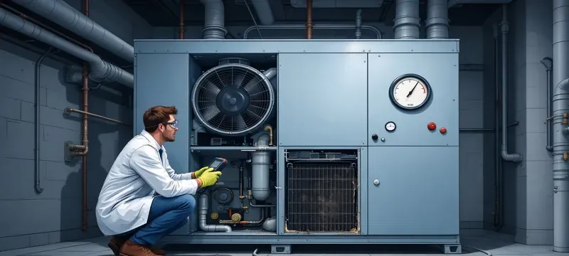
Review the filter for loading, obstructions or damage. Then check HVAC filter airflow and static pressure together before concluding anything. Examine the rack for bypass leaks & the gaskets for compression and failure. Evaluate fan operation & coil performance. If filter pressure reading is within limits, but there is a problem of low airflow, then the difficulties may be in the downstream location.
This matrix takes you from symptom to check to next step of corrective action for low airflow and high pressure drop and pressure imbalances. The matrix may be used to make the diagnosis of the whole system before changing or downgrading the filter.
In the event that the limits are reached, put back the proper filter configuration and diagnose the system. One should not use higher-MERV filters in systems not designed for using them. The failure should be recorded as well as the repair procedure used.
Deiiang product evidence and project application
The company manufacturers cleanroom filters which have complete catalogue data for H13, H14, U15, U16, and U17 filters. High-efficiency HVAC air filters sit in the same catalogue but are selected on a different basis. The DOP Integrated Filter is designed for cleanrooms with height restrictions. The Combined High-Efficiency Filter is intended for terminal filtering in air conditioning systems and purifying systems.
Outcomes from the project should be recorded apart from catalogue data. The catalogue data is the standard which was obtained during factory testing. The project outcomes refer to testing results computed and applied in field conditions in the office.
Present a project case study
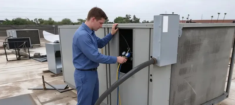
The commencement of project operations and the selection of sampling methodology remain undisclosed, and client consent is still being awaited. In this project, Deiiang made use of low-profile H14 high-efficiency filter units with silicone-free gaskets, as well as F7 type prefilters.
The photograph illustrates the kind of low-profile H14 filter installation described in this case, rather than a record of one specific site.
Illustrative images of this kind help to visualise how such filter units fit into a plenum with limited space.
Project Outcome: Particle counts exhibited a downward trend from iso 7 baseline level to stable ISO 6 level. The stable ISO 6 level indicates that the particle counts in specified sampling points remained below the levels that qualify as iso 14644-1 class 6 territory. The claim made regarding energy savings is void as accurate energy data measuring the efficiency of the filters were not presented for verification. The outcomes reported here are from the client; no independent verification is possible.
Connect catalogue data to field selection
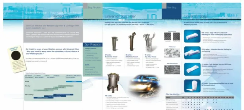
When selecting a filter, follow the specifications for airflow and pressure drop as presented in the catalogue. According to Deiiang's catalogue data, the Combined High Efficiency Filter has a capacity of 2,500 m³/h with initial resistance of 220 Pa or less for H14 filter and 20.04 m² of media area. The final stage is the addition of a prefilter that will minimize the loading without causing excess resistance.
This matrix presents all the necessary information from the catalogue on selected Deiiang models, their respective airflow ratings, initial pressure drops, and media area for each unit as determined through testing. It justifies the use of both the filter pressure drop and the maximum allowable TESP for the system instead of solely using the nominal pressure drop.
For example, in the flow rate of 2,000 m³/h with a maximum allowable TESP of 250 Pa, the H14 filter has a catalog pressure drop of approximately 180 Pa at that same flow rate. This arithmetic is what MERV rating compatibility means in practice. This means that the remaining pressure drop allowance of 70 Pa must be used for the prefilter, the coil, and the ducts.
If the sum of the pressure drops for all of those components is greater than 70 Pa, the configuration is deemed incompatible. When selecting filters, make sure that the comparison is not made based on previously tested pressure drops from different filters or used for different airflow rates or configurations.
Common upgrade mistakes and decision summary
When selecting a filter, it is important to not select based upon the MERV rating of a filter only. In addition, one should not overestimate the dimensions and the bypass gaps during installations.
Using the decision of “proceed,” “test,” or “reject,” one should use “proceed” when the addition of the filter class is approved during the measurement of airflow within the allowable range. Use “test” when the filter documentation is missing pertinent information. Use “reject” when the filter impairs airflow or exceeds the allowable pressure.
Avoid common selection and installation errors
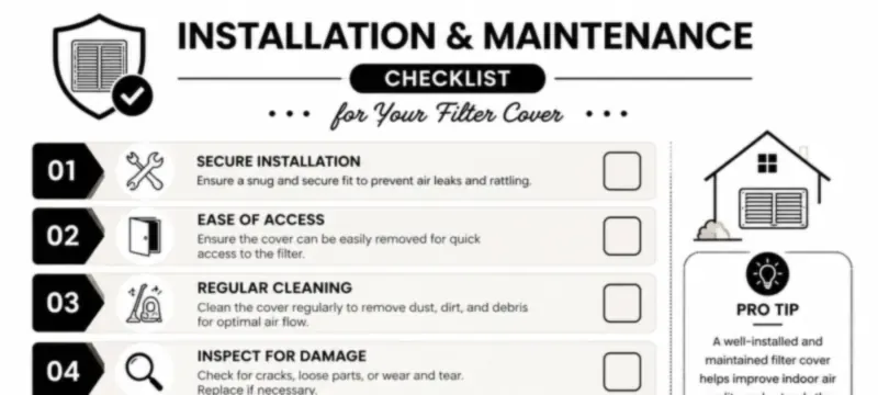
When comparing MERV ratings across different tested conditions, ensure that the standard that was tested is logged. Avoid installing a filter that is smaller than the mount of the rack. Avoid reusing the gaskets from previous filters. Ensure that you respect the manufacturer’s pressure limit.
This illustration compares a well-sealed filter system with compressed gasket edges to an installation prone to bypass leakage with visible gaps in the gasket sealing surface. It helps support the inspection and repair of the seal prior to testing the performance of the filters.
In a properly sealed installation, all air must pass through the filter media rather than leaking around the frame like an installation that allows bypass leakage. The bypass effect may be more significant than differences in MERV ratings. Deiiang stresses the importance of gasket integrity and frame compatibility in filter selection.
According to Jason Peng, a product designer at Deiiang, “The most frequent mistake made in the filter selection process is the selection based solely on the MERV or class with no regard to the actual pressure drop at the air flow of the system. More media equates to lower resistance at the same air flow rate, and therefore we want to be certain of fit and seal before making recommendations.”
Decide whether to proceed with the upgrade
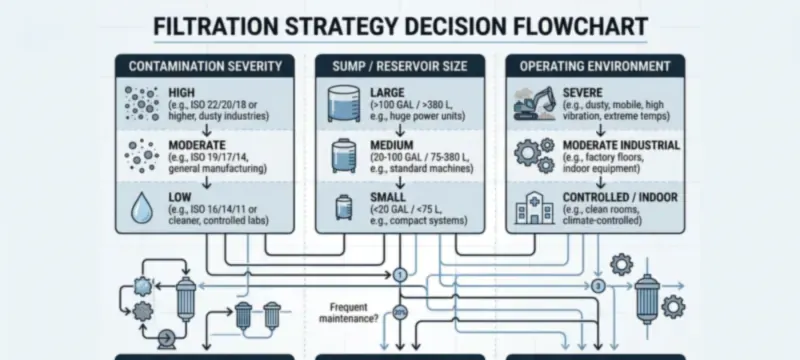
Proceed only within the limits of proposed equipment and with verification of fit and air flow. No higher MERV filter HVAC decision should be made on the filter data alone. Measure suspected configurations with pre- and post-installation measurements. Do not choose configurations that adversely affect air flow values. Remember to record approvals and results.
The sequence above provides guidance on whether to proceed, test, or reject the upgrade based upon the status of documentation, fit, and post-installation measurement results. Proceed only when all criteria are met.
For example, a project-specific guideline for the HVAC would be to maintain positive pressurization of air through the system. This guideline is an example and does not mean it is the same for everyone.
The user of the HVAC equipment or an HVAC professional is responsible for determining the conditions under which the equipment should be tested and the subsequent actions if the testing does not meet the standards.
Frequently Asked Questions
Can I use a higher MERV filter in my HVAC system?
Yes, if the equipment manual states that it is okay to use a high-efficiency filter, the filter fits and seals properly, and the resulting air measurements after the installation meet the air flow and pressure requirements of the equipment. If any of those conditions cannot be guaranteed, then the user must abide by the original MERV rating of the filter approved for use.
Will a higher MERV filter reduce airflow?
A filter with a higher MERV rating has the potential to create back pressure if the system is already operating at a high static pressure condition. This will depend on the increasing filter pressure drop created by the filter at the air flow rate being measured during the testing.
Does a higher MERV filter always increase energy use?
No. The amount of energy used depends on filter resistance, fan control, loading, and operating hours. A variable-speed fan may respond differently from a constant-speed fan, so avoid universal claims.
How do I know which furnace filter MERV rating is allowed?
Check the installation manual for the air handler or furnace for the specified MERV or pressure drop limit approval. Confirm the actual size of the filters and the gasket type. If a limit is not stated in the manual, check with the manufacturer of the equipment, or have an experienced HVAC technician look at the system; the lack of a limit does not mean it is acceptable.
Is a high-MERV filter a HEPA filter?
No. MERV is based on ASHRAE 52.2, while the classifications for HEPA filters are based on EN 1822 or ISO 29463. A MERV 16 filter does not mean it is a HEPA H13 or H14 filter. Request testing documentation for any HEPA claims per applicable HEPA standards.
Does a cleanroom need a higher-MERV HVAC filter?
A cleanroom needs a filtration strategy depending on risk of the room based on ISO 14644, and not based solely on MERV levels. The cleanroom air filter selection usually involves a pre-filter and HEPA or ULPA final filter stage tested in accordance with EN 1822 or ISO 29463. The MERV rating compatibility is one step in choosing the cleanroom air filter system.
References
- [1] ASHRAE Standard 52.2-2017 - standard method of testing general ventilation air-cleaning devices for removal of airborne particles.
- [2] ISO 16890-1:2016 - air filters for general ventilation - Part 1: Technical specifications, requirements and classification system based on efficiency for particles.
- [3] EN 1822-1:2019 - high efficiency air filters - EPA, HEPA, and ULPA classification, test criteria, and marking.
- [4] ISO 29463-1:2017 - high efficiency filters and filter media for air particle removal in air.
- [5] EN 779:2012 particulate air filters for general ventilation - outdated; reference listed for historical context only.
- [6] iso 14644-1:2015 cleanrooms and related controlled environments - standard for air cleanliness by particle count.
- [7] iso 14644-3:2019 cleanrooms and controlled environments - testing methods.
- [8] IEST-RP-CC001.7:2022 HEPA and ULPA filters.
- [9] MIL-STD-282, method 102.8 - DOP smoke passage of aerosol filter - application of DOP smoke test.