+86 13638632902
 Jason@cleanroomequips.com


 MENU

The airflow resistance of a medium filter is its pressure drop measured across that filter at a specified airflow rate, defined in terms of a single, measurable number provided both the rate of airflow and the model of filter are provided along with parameters applicable to that measurement.
For example, in the catalogue reference provided by Deiiang, the 592 x 592 x 381 mm 6-bag medium filter is listed as having an airflow rate of 2050 m3/h with an initial resistance of less than 50 Pa in F5 and less than 100 Pa in F8.
The air filter pressure loss values provided above in the reference provided by Deiiang apply to the model specified and tested under the stated conditions rather than to every medium-efficiency filter tested under a stated set of test parameters.
In some instances, it might be stated that the acceptable airflow resistance allowable for clean medium filters is between 30 Pa and 150 Pa, but this will usually only apply to the model tested, so it must be regarded as nothing more than a rule of thumb.
This article will define what the term “resistance” means, what factors influence it, how it is measured, how it relates to the selection of filtered HVAC units, how previous catalogue data from Deiiang deviate and how one can troubleshoot high resistance readings, and what governing standards exist. Illustrations apply engineering principles unless otherwise indicated in the caption.
Author note: this document on filter resistance measurement has been produced utilizing input provided by Jason.peng of Deiiang, a manufacturer of cleanrooms and air filters (cleanroomequips.com). All statements will reference whether they come from catalogue data, general engineering principles or reported project results.
What airflow resistance means for a medium filter
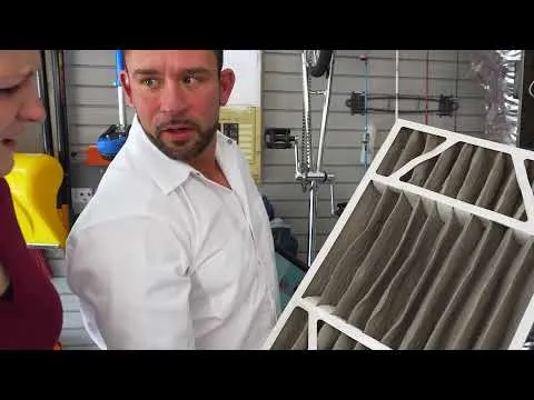
The airflow resistance of a medium filter is defined as the energy consumed by fans in moving air through media, pleats and frame. It appears as the difference in static pressure from the upstream and downstream side of a filter, read with the aid of either a manometer or a differential pressure gauge.
The relevance of any medium-efficiency filter resistance figure is contextual. For example, a medium filter working at 1700 m3/h and 2050 m3/h gives different metrics. Other factors such as sealing condition, face velocity, effective media area, and dust load also vary its value.
How pressure drop describes airflow resistance
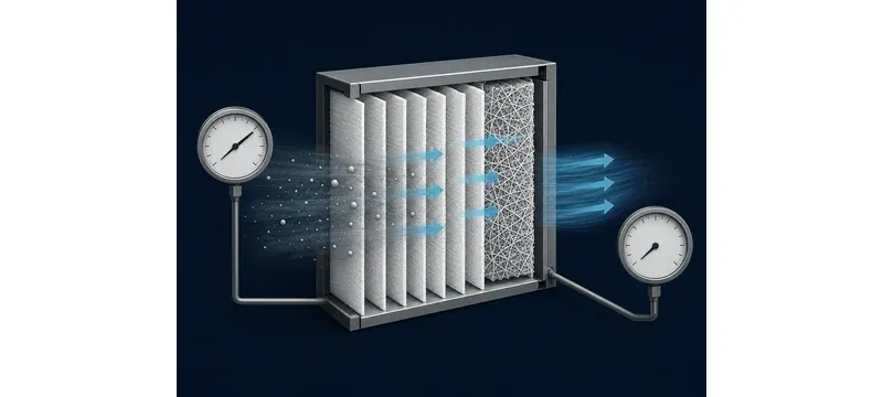
The air filter pressure loss is most often expressed as a pressure drop in metric units like Pascal (Pa) and Imperial units like inch water gauge (in. w.g.) where 1 in. w.g. is equivalent to around 249 Pa. This value is used to make comparisons between the static pressures on either side of the filter only.
As a thumb rule, the medium filter airflow and the pressure drop are related by a square law. It is only a rough approximation and it depends on the model. It does not take into account the changes in flow regime, media compression, and loading pattern.
A filter cataloged at 100 Pa and 2050 m3/h of medium filter airflow will have an approximate pressure drop of 100 x (1700/2050)2 = 69 Pa at 1700 m3/h. However, this is an illustrative value and is not meant to be a predicted or guaranteed value for field applications.
How resistance differs from filtration efficiency
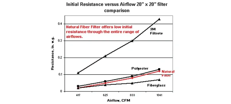
Filtration efficiency is indicative of the percent of particles captured, whereas the medium air filter pressure drop pertains to pressure loss. It is imperative to remember that the two terms are different and should always be stated separately. A thicker or denser product will typically lead to a higher resistance, however, in this case, the nature and configuration of the media may outweigh a simple comparison of thickness.
There will also be different classification systems used as well. For example, different methods of testing have been employed for the EN 779 grades, ASHRAE MERV, and ISO 16890 classes since the test aerosols, particle size bands, and rules used for classification are different [2][3]. They should not be treated as being identical.
When a catalog gives a nominal efficiency for 0.5 µm, it should be clear what test was done and under what conditions. For example, Deiiang’s catalog shows 45% efficiency for F5 and 90% efficiency for F8 at 0.5 µm, with eACH having an initial resistance of less than 50 Pa and less than 100 Pa respectively on the six bag 2050 m3/h platform.
Those efficiencies should be treated as catalog values for that version of the product [1].
What determines medium-filter resistance
Five groups of factors affect medium-efficiency filter resistance readings; the permeability of the medium, pleat or pocket geometry, face velocity and flow rates, frame and sealing conditions, and dust loading. The permeability of the medium is a greater factor than the medium type alone.
Only compare tested units using the same airflow, face size, efficiency basis, and testing conditions, because the airflow resistance of a medium filter is only meaningful at a stated rating point. Any comparison using different face sizes or grades is a reflection of geometry rather than quality of medium.
How filter construction affects resistance
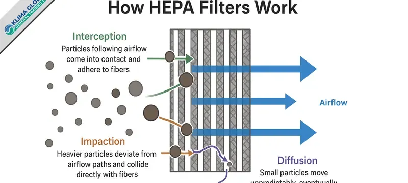
Effective media area is one of the levers that can be used to set the airflow resistance of a medium filter. More effective area will allow the media to lower the velocity of the air flowing through it, thus reducing the filtering pressure drop across the medium air filter. Deiiang catalog shows 3.18 m2 for the 592 x 592 x 381 mm six-bag model, but please check with the manufacturer if it still applies for this version [1].
The design of the pleat or pocket geometry dictates the uniformity of the effective area. Irregular spacing among the pleats, collapsed pockets, or blocked spaces may lead to the creation of zones with local high-speed flow, increasing resistance.
The frame and sealing design should have a relatively lesser role. The media is held in position by aluminum frame profile, PU two-component sealant, and adhesive board-paper dividing panels. The compressive resistance of the gasket has more effect on leakage, affecting bypass leakage more than significant resistance through the media, therefore affecting the readings.
How airflow and installation affect readings
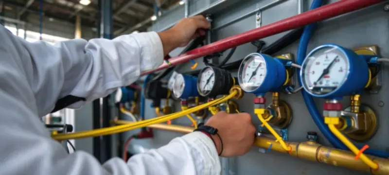
The face velocity is the medium filter airflow divided by the face area. A face of 592 x 592 mm means roughly a face area of 0.35 m2 and so at a volumetric flow of 2050 m3/h the face velocity is about 1.63 m/s, while it is slightly higher at 1.98 m/s at 2500 m3/h.
The installation also plays a role in determining the medium air filter pressure drop readings. If there is any gap around the frame, the air is allowed to slip by thus reducing the apparent resistance value and accordingly reducing efficiency. If gaskets are compressed too much, they can lead to distortion of the frame creating further zones of high-velocity air flow.
Obstructions such as dampers, coils, or sharp bends may create different velocity profiles and distort the medium air filter pressure drop. Therefore, a filter with a non-uniform airstream can have an increased average value derived from higher localized loading of the filter against its face.
Measuring pressure drop and tracking filter condition
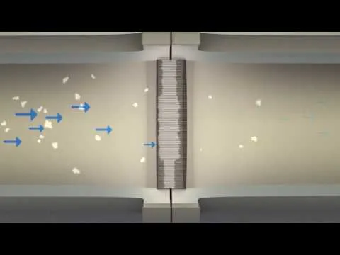
The measurement of the airflow resistance of a medium filter is theoretically simple but practically complicated. The discipline is ensuring that the airflow and operational state are also recorded whenever a reading is made, so that all measurements can be compared throughout the life of the filter.
There are two variables that define filter maintenance: the HVAC filter initial pressure drop of the clean element and the resistance given by the manufacturer for that model.
How to measure and record filter pressure drop
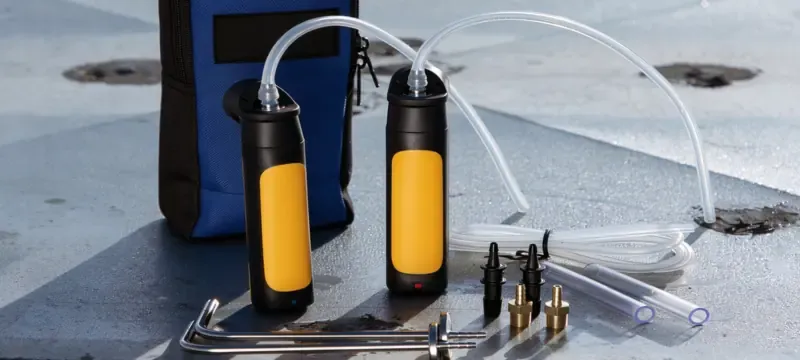
To ensure repeatability, one should implement a fixed sequence when measuring and recording medium-efficiency filter resistance.
A single medium air filter pressure drop reading will not be very informative, as it cannot indicate normal or accelerated loading; therefore the data should be analyzed in conjunction with pressure drop limits established by the manufacturer for making decisions regarding the replacement of filters.
Table 1: Interpreting differential pressure readings (general engineering guidance)
| What you observe | What to compare it with | Action |
|---|---|---|
| Clean filter, first reading | Record initial reading at the operating airflow of the system | Record and keep as the baseline for this position |
| Slowly rising reading | Catalogue previous readings at the same flow condition and fan state | Monitor and confirm that airflow is not affected yet |
| Reading is close to maximum resistance set out by the manufacturer | Manufacturer's maximum resistance for this particular configuration | Make plans for replacements; investigate fan capacity surplus |
| Reading is over the noted maximum resistance | Manufacturer's maximum resistance plus airflow and cleaning conditions for the facility | replace the equipment or do it according to the monitored procedures outlined in the facility |
| High reading at the beginning of operation | It may involve instruments being set for zero, tap position, airflow rate, speed at the fan, installation, and sealing | Verify it to prevent errors from arising at first |
| Abnormal behavior, sudden drop in reading | Filter media getting damaged, rupture or bypassing that occurs around the frame | Check at once for both filter and sealing |
| Erratic and unstable reading | Blocked tap, kinked tubing, condensation, issue with the gauge instrument | Check the gauge to avoid any errors in treatment |
| What you observe | Compare with | Action |
|---|---|---|
| Clean filter, first reading | Operating airflow baseline | Record as baseline |
| Slowly rising reading | Previous readings at same flow | Monitor airflow |
| Close to manufacturer maximum | Manufacturer maximum for configuration | Plan replacement |
| Over noted maximum | Manufacturer maximum plus facility conditions | replace per facility procedure |
| High reading at start | Zero, tap, airflow, fan speed, sealing | Verify before acting |
| Sudden drop in reading | Media damage, rupture, bypass | Check filter and sealing |
| Erratic reading | Blocked tap, tubing, gauge fault | Check gauge |
There are no multipliers or absolute limits for the air filter pressure loss when assessing the status of filters. The manufacturer is the authority on final resistance points as well as the standards for the facility have come into play.
How initial and final resistance guide maintenance
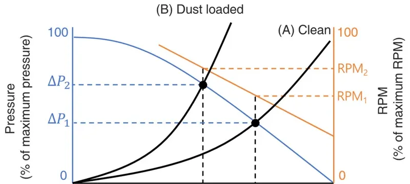
Deiiang catalogue data lists filter replacement pressure drop values of between 250 and 400 Pa for medium-efficiency bag filters and between 400 and 600 Pa for the high-efficiency series, so proper values must be confirmed based upon the model and revision.
Neither of these filter replacement pressure drop figures is universal, as replacement may be required earlier based on airflow dropping below the cleanliness requirement, if there is moisture or damage of media or based on facility procedures.
Selecting a medium filter for cleanroom HVAC
Cleanroom HVAC filter selection references pressure drop which is pressure lost due to airflow of filter, efficiency class, physical dimensions and sealing properties of filter. Filter must function by providing amount of required air without exceeding ability of fan static pressure and it must seal properly in all cases as required.
How to match filter size and airflow to the system
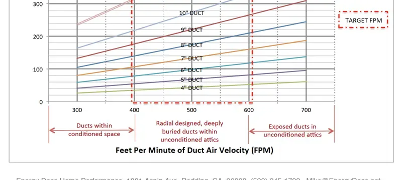
Cleanroom HVAC filter selection by size starts with the design airflow of the filter than evaluating grade based on cataloged value selected for model filter size and type of filter including face size and depth.
For instance, cleanroom HVAC filter selection has to note how there may be multiple configurations available for filtration performance dependent upon model and configuration of chosen unit and not only based upon grade of filter being selected [1].
Table 2: System-to-filter selection checks (general engineering guidance)
| Check | Required system information | Specification to verify |
|---|---|---|
| Physical fit | Frame dimensions, available depth, flow path | Dimensions per catalog, frame type, depth |
| Airflow through one filter | AHU or terminal design flow and filter positions | Airflow under stated resistance for the defined model |
| Fan available static pressure | Static fan curve, system losses, component pressure drop | Catalog initial resistance at airflow to system |
| Efficiency class or specification required | Size of target particles, cleanliness class, specification | Quality class specifically with test method included |
| Initial pressure drop | Design flow margin on fan curve | Catalog initial resistance indicating test parameters |
| Final resistance allowance | Static pressures during the loading cycle based on maintenance policy | Resistance as stated by the manufacturer |
| Sealing | Frame face, how to compress the gasket, contamination prevention | Seal material and design, silicone-free options as needed |
| Operating conditions | Temperature and humidity extremes | Max temperature and humidity ratings |
| Check | System information | Verify |
|---|---|---|
| Physical fit | Frame dimensions, depth, flow path | Dimensions, frame type, depth |
| Airflow through one filter | AHU design flow and filter positions | Airflow at stated resistance |
| Fan available static pressure | Fan curve, system losses | Catalog initial resistance |
| Efficiency class | Target particles, cleanliness class | Class with test method |
| Initial pressure drop | Design flow margin on fan curve | Catalog initial resistance |
| Final resistance allowance | Loading cycle, maintenance policy | Manufacturer resistance |
| Sealing | Frame face, gasket compression | Seal material and design |
| Operating conditions | Temperature and humidity extremes | Max ratings |
How to balance pressure drop, efficiency, and operating cost
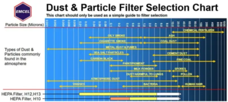
Pre-selection of filters must be made based on target cleanliness rating, the acceptable HVAC filter initial pressure drop, and system design in accordance with specifications. Application of common sense facility guidelines are no longer sufficient. Selection of grades should be based on the actual loading present as well as the target class rather than simply by facility types.
For filter resistance measurement in service, it is possible to estimate fan energy from the pressure drop via the following formula: P = Q x dP / n. Assumed calculations: Q = 2.0 m3/s (7200 m3/h), dP = 50 Pa, fan efficiency = 0.65.
For that filter resistance measurement, then P = 2.0 x 50 / 0.65 = 154 W. Therefore, over a total of 6000 hours of operation, 923 kWh would be consumed annually. Both the result and value will be changed by the assumptions.
Deiiang product data and application validation
Deiiang catalogue data provides designers with base information; however, each medium filter airflow rating must be read together with the model and the conditions used during the tests. The information of manufacturers’ catalogues is segregated from the data of guidelines in this section.
Table 3: Comparison of the Deiiang catalog data (use manufacturer's catalog data and make sure current revision is checked prior to specifying) [1]
| Family and dimensions | Efficiency class and standard | Rated airflow | Initial resistance | Final resistance | Source note |
|---|---|---|---|---|---|
| Medium glass fiber bag, 592 x 592 x 381 mm, six-bag | F5 (old EN 779 ratings) | 2050 m3/h | Below 50 Pa | 250 to 400 Pa | Deiiang medium filter catalog |
| Medium glass fiber bag, 592 x 592 x 381 mm, six-bag | F8 (old EN 779 ratings) | 2050 m3/h | Below 100 Pa | 250 to 400 Pa | Deiiang medium filter catalog |
| Medium synthetic bag, 1000 m3/h configuration | F6, F7, F9 | 1000 m3/h | To be confirmed with manufacturer | 250 to 400 Pa family figure | Deiiang medium filter catalog |
| Medium synthetic bag, 1700 m3/h configuration | F5, F9 | 1700 m3/h | To be confirmed with manufacturer | 250 to 400 Pa family figure | Deiiang medium filter catalog |
| W-bank combined, 23 x 23 x 11.5 in | F7 | To be confirmed with manufacturer | To be confirmed with manufacturer | To be confirmed with manufacturer | Deiiang medium filter catalog |
| W-bank combined, 11.3 x 11.3 x 11.5 in | F8 | To be confirmed with manufacturer | To be confirmed with manufacturer | To be confirmed with manufacturer | Deiiang medium filter catalog |
| V-bank combined activated carbon | Gas and odor duty; particle grade not applicable | 3700 m3/h | To be confirmed with manufacturer | To be confirmed with manufacturer | Deiiang medium filter catalog |
| High efficiency combined, 592 x 592 x 292 mm | H14 (EN 1822) | 2500 m3/h | At or below 220 Pa | 400 to 600 Pa | Deiiang high efficiency catalog |
| Family and dimensions | Efficiency class | Airflow / resistance |
|---|---|---|
| Medium glass fiber bag, 592 x 592 x 381 mm, six-bag | F5 (old EN 779) | 2050 m3/h; below 50 Pa; final 250-400 Pa |
| Medium glass fiber bag, 592 x 592 x 381 mm, six-bag | F8 (old EN 779) | 2050 m3/h; below 100 Pa; final 250-400 Pa |
| Medium synthetic bag, 1000 m3/h configuration | F6, F7, F9 | 1000 m3/h; initial TBC; final 250-400 Pa |
| Medium synthetic bag, 1700 m3/h configuration | F5, F9 | 1700 m3/h; initial TBC; final 250-400 Pa |
| W-bank combined, 23 x 23 x 11.5 in | F7 | TBC |
| W-bank combined, 11.3 x 11.3 x 11.5 in | F8 | TBC |
| V-bank combined activated carbon | Gas and odor duty | 3700 m3/h; TBC |
| High efficiency combined, 592 x 592 x 292 mm | H14 (EN 1822) | 2500 m3/h; at or below 220 Pa; final 400-600 Pa |
Which Deiiang specifications to compare
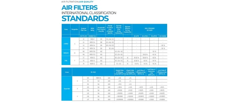
You will compare five values together, never alone: rated airflow, the HVAC filter initial pressure drop at that airflow, final resistance, efficiency class with standard named, and effective media area. It is worth noting that two models can have the same grade and still have large differences in resistance, because face size, depth, and the media area can be very different.
For pre-filtration prior to HEPA, the medium glass-fibre bag family covers 1700 m3/h and 2050 m3/h catalogue ratings, and the synthetic family covers 1000 m3/h and 1700 m3/h ratings (see F5 to F9 filters). In the V-bank activated carbon combined unit, the catalogue gas and odour duty rating is 3700 m3/h (when particulate filtration alone is inadequate) [1].
How to validate catalogue data for site conditions

The catalogue HVAC filter initial pressure drop is stated in a measured condition, usually clean media at rated airflow. However, site conditions are not the same: altitude, air temperature, humidity, and the actual airflow delivered, alter the reading.
Indeed, just keep expectations aligned with the earlier discussion, since the airflow resistance of a medium filter changes with every adjustment listed above. If a filter was a near stable reading 100 Pa at 2050 m3/h, and it is now being used in a system where it runs at 1700 m3/h the illustrative estimate debtor to 69 Pa.
Or at 2300 m3/h it would be about 126 Pa. Still, these are both not prediction nor guaranteed in a site value.
Request samples of the pressure-drop versus airflow curve for the actual model, which is the only reliable way to establish the airflow resistance of a medium filter, prior to coming to a conclusion on fan selection. Deiiang will test high-efficiency filters once prior to shipping; ask for it - what the test was, against what acceptance criterion and in what format, because "tested" is not evidence unless objective and defined a method.
Troubleshooting high resistance and filter replacement
A high medium air filter pressure drop should not be assumed to be a fault with the filter. It may be an infection of the system, pressure problem, airflow problem, instrument fault, or installation error. Check through the sequence before you order replacement filters.
What causes unexpectedly high resistance readings
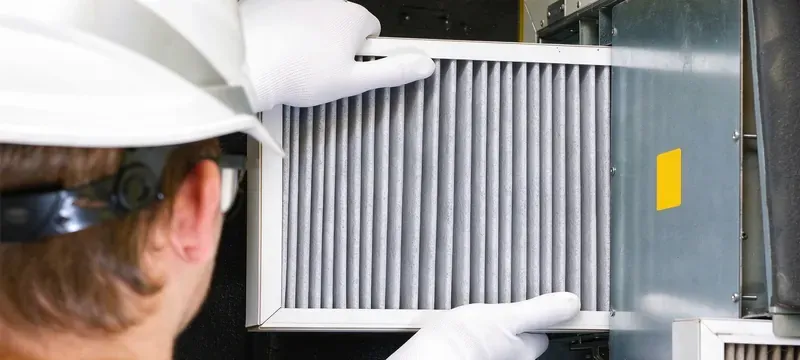
For a reliable filter resistance measurement, work methodically and stop when the cause is identified:
When to replace a medium filter
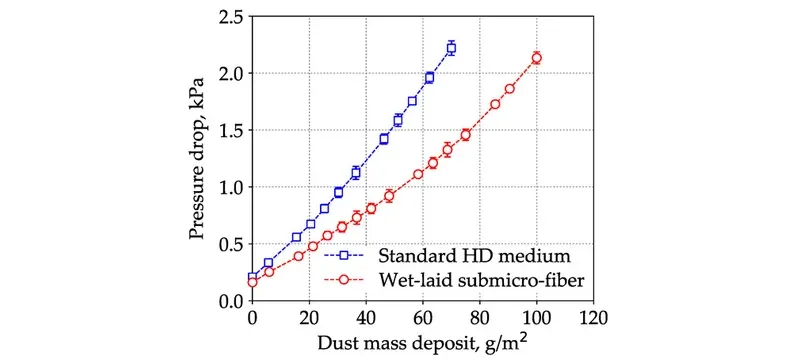
replace the filter when the HVAC filter initial pressure drop reaches the manufacturer's maximum for that model, or sooner if airflow, cleanliness, damage, or related operating procedures dictate. Deiiang catalog indicates max values from 250 to 400 Pa for medium-efficiency bag filters, but check for values for each model and revision [1].
Do not assume a fixed value is correct for all filters. A filter running above its maximum will require additional fan power and potentially drop supply airflow below the required amount for cleanroom specification. Use previous media if it is moist or damaged since the damaged filter can cause cleanliness problem before reaching the pressure threshold.
Take notes on the performance; date, filter model, the filter replacement pressure drop reached, airflow, and fan operation.
Standards and testing for filter performance
Standards specify how the test measurements and classifier system work. The standards to which filters fall depend on the class of filter; they have different scopes. None of the standards sets a universal limit on medium filter pressure drop.
Which standards apply to filter testing and classification
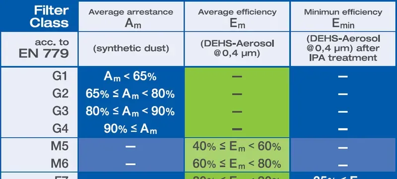
ISO 16890-1:2016 is the current general-ventilation standard that classifies filter to the ePM1, ePM2.5 and ePM10 standard [2]. While ISO 16890-1:2016 has replaced EN 779, the legacy of F5 to F9 designation will still show in product catalogs and specifications where the previous standard appears. Therefore, it is essential to make sure of the standard and make reference to EN 779.
ASHRAE 52.2-2017 defines the MERV ratings associated with testing of general-ventilation filters for particle size removal efficiency [3]. MERV and ISO 16890 have different methods of compulsorily established classification system.
EN 1822-1:2019 specifies the classification of EPA, HEPA and ULPA filters (including H13 and H14 grades used in Deiiang High Efficiency catalog data) [4]. The same filter family is covered by ISO 29463 at the international market [5]. Neither of the standards specifies the classification of medium filter resistance.
iso 14644-1:2015 gives a cleanroom classification system based on the concentrations of airborne finder particles contained in the cleanroom. IEST-RP-CC001 stipulates the principles associated with the performance of HEPA and ULPA filters for cleanrooms; applicable efficiency and test specifications should be determined according to the present revision and not generalized into an all-encompassing number [7].
MIL-STD-282 Method 102.8 defines the DOP test that has traditionally been utilized to identify a filter’s penetration characteristics; although it is still mentioned in some contracts, the standard presently needs to be thought of as a historical reference [8].
Table 4: Standards scope and applicability (check current editions)
| Standard | Scope | Applicability to medium filters / cleanrooms |
|---|---|---|
| ISO 16890-1:2016 | Clean air filter testing and classification | Currently used for calculating the applicable ratings of ePM1, ePM2.5, and ePM10 related to medium filters |
| EN 779 (withdrawn) | Previous clean air classification | In historical context only; grades of F5 to F9 can still be found in some catalogs |
| ASHRAE 52.2-2017 | Tests for minimum efficiency reporting value of filters | Used for a clean air filter classification in general terms rather than to measure pressure drop |
| EN 1822-1:2019 | HEPA, ULPA, and EPA classification | Defines the H13 and H14 classes of HEPA and ULPA filters for testing purposes; will not characterize medium filter resistance |
| ISO 29463 | Globally standard classification protocols | Establishes a uniform standard for HEPA/ULPA filter classification internationally |
| IEST-RP-CC001 | HEPA and ULPA filter specifications for cleanrooms | Construction and testing requirements; currently utilized for standard reference |
| MIL-STD-282 Method 102.8 | Historical DOP testing specification | Historical identification of penetration performance; still referenced in some contracts |
| iso 14644-1:2015 | cleanroom classification by particle concentration | Defines applicable cleanroom classification to be satisfied by the filter system |
| iso 14644-3:2019 | cleanroom testing procedures | Defines the manner in which the performance of the filter system will be verified |
| Standard | Scope | Applicability |
|---|---|---|
| ISO 16890-1:2016 | General ventilation filter testing | ePM1, ePM2.5, ePM10 ratings for medium filters |
| EN 779 (withdrawn) | Legacy general ventilation classification | Historical context; F5 to F9 still in catalogs |
| ASHRAE 52.2-2017 | MERV rating by particle size | Efficiency classification, not pressure drop |
| EN 1822-1:2019 | EPA, HEPA, ULPA classification | H13 and H14 classes; not medium filter resistance |
| ISO 29463 | International HEPA/ULPA classification | Aligns HEPA and ULPA classes globally |
| IEST-RP-CC001 | HEPA/ULPA filters for cleanrooms | Construction and test provisions |
| MIL-STD-282 Method 102.8 | Historical DOP test | Legacy penetration test reference |
| ISO 14644-1:2015 | Cleanroom classification | Defines class to be met by filter system |
| iso 14644-3:2019 | cleanroom test methods | Verifies installed filter performance |
How standards inform cleanroom filter selection
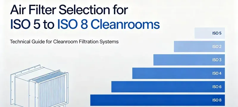
The standards provide a common terminology which facilitates cleanroom HVAC filter selection. The cleanliness objective is derived from the related classification and the filtration system should be able to achieve this with a suitable airflow and pressure drop.
When putting into practice, pre-filters ahead of HEPA filters are selected because they alleviate the pressure on the final particle filtration stage, without imposing excessive resistance to airflow. Which type of pre-filters is used depends on the amount of particles that enters the cleanroom, the cleanliness classification that is to be achieved, and type of facility operating specifications.
In order for the air filter pressure loss of the air-cleaning system in the cleanroom to be verified, the relevant cleanroom testing procedures should be followed since there are particle counting, leak testing, and airflow testing methodologies for cleanroom testing purpose.
Deiiang project case study and practical recommendations
This case study involves an actual case, which has been reported by one of the Deiiang project teams. The project results are reported as promised and not yet certified; measured data other than mentioned is available only to the facility and their contractor.
What were the project conditions and Deiiang’s solution?
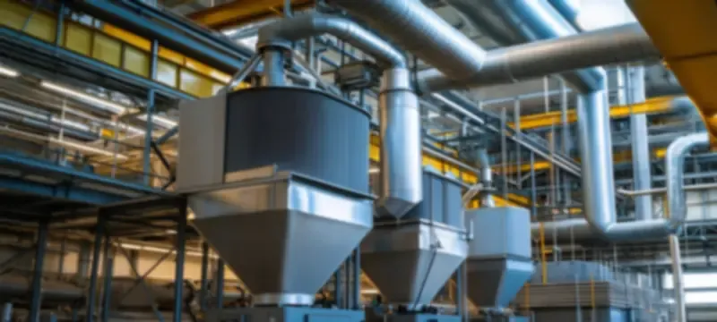
It was a pharmaceutical cleanroom facility with a high ambient particle load and limited plenum height, which constrained cleanroom HVAC filter selection while still ensuring strict pressure drop limits. In the original design, it was named the class 1000 facility, which is sometimes used in an approximately comparable sense to ISO 6; however, legacy designations do not directly equal iso classes, while project records indicated that the facility was initially designed as close to ISO 7 as possible.
Since plenum depth did not allow for deeper array, Deiiang provided shallow profile H14 combined high-efficiency filters 592 x 592 x 292 mm, catalog rated at 2500 m3/h with 20.04 m2 of media area and initial resistance below 220 Pa. The catalog shows the final resistance on the filters being between 400 and 600 Pa and the dust holding capacity to be approximately 1200 g for that model [1].
Included in the package are silicone-free sealing gaskets and F7 pre-filters, along with per unit DOP scan testing prior to shipment.
What verified results and lessons can other facilities use?
Reported results highlight that particle counts moved from ISO 7 baseline to stable ISO 6 based on routine particle monitoring by the facility according to its own sampling plan. Instrument model, sampling points, and raw counts will not be shown here.
The project team stated that lower fan energy was experienced with the low resistance final filter versus the alternative considered; however, no metered before and after comparison is provided here and thus the energy claim should be taken qualitatively.
Lessons that are transferable include matching filter depth to available plenum and the expected medium-efficiency filter resistance before choosing a grade; specifying sealing material due to contamination needs; staging pre-filters in such a way that the final stage is loaded slowly; and finally recording initial resistance upon commissioning so later readings have a point of reference.
Frequently Asked Questions
What is the airflow resistance of a medium filter?
It’s the pressure loss across the filter at designated airflow. As per the example of Deiiang’s catalogue, the clean 592 x 592 x 381 mm six-bag configuration has less than 50 Pa resistance in category F5 and has less than 100 Pa resistance in category F8 at volume flows of 2050 m3/h. These values are catalogue based on the specific characteristics of the equipment and should be updated prior to making the final decision.
How is medium-filter airflow resistance measured?
The measurement of the air filter pressure loss involves checking the difference in static pressure across both ends of the filter through a duly calibrated differential pressure gauge. More preferably, ensure system stabilization, check device zero point, and record air volume, such as the flow rate, and the fan speed at the same instant as a drop in pressure but no flow is of slight importance.
What is a normal pressure drop for a medium filter?
There is no defined value for the HVAC filter initial pressure drop. The generalized range is sometimes provided as 30 Pa to 150 Pa where medium efficacy filters are clean; however, this value may not hold for all cases due to other conditions being present. It is advisable to employ the manufacturer’s catalog value of initial resistance and then evaluate how it varies with the baseline.
What causes a medium filter’s resistance to increase?
The principal reason for a rising medium air filter pressure drop is dust loading. Higher actual airflow, malfunctioning of the media, incorrect installation, and unsteady upstream airflow can also lead to inaccurate readings. Faulty equipment and obstruction of taps can result in false readings, which are corrected upon inspection of the gauge.
When should a medium filter be replaced?
Filters must be changed when the filter replacement pressure drop reaches the final documented resistance of the manufacturer for a particular model, or sooner depending on the factors of airflow, contamination, damage, and procedure.
How can I choose a medium filter with suitable airflow resistance?
Ensure that the rated airflow of the specific model is identical to the airflow being designed, then compare the initial resistance from the catalogue at that airflow with the static pressure available from the fan. Use the lowest efficiency class that is sufficient in meeting cleanliness standards and relevant specifications; verify that the dimensions, depth, gasket type, and final resistance are in order.
References
- [1] Deiiang medium-efficiency and high-efficiency filter catalogue information, provided by Deiiang, cleanroom and air filter manufacturer (cleanroomequips.com). Information is manufacturer catalogue data; always verify current catalogue revision, model number, rated airflow, and testing conditions of each model prior to specification.
- [2] ISO 16890-1:2016, Air filters for general ventilation — Part 1: Technical specifications, requirements and classification system. International Organization for Standardization. Document record available from the ISO standards catalogue (iso.org).
- [3] ANSI/ASHRAE Standard 52.2-2017, Method of Testing General Ventilation Air-Cleaning Devices for Removal Efficiency by Particle Size. ASHRAE. Document record available from the ASHRAE bookstore (ashrae.org).
- [4] EN 1822-1:2019, High efficiency air filters (EPA, HEPA and ULPA) — Part 1: Classification, performance testing, marking. CEN. Document record available from the CEN standards catalogue.
- [5] ISO 29463-1:2017, High-efficiency filters and filter media for removing particles from air — Part 1: Classification, performance testing and marking. International Organization for Standardization. Document record available from the ISO standards catalogue (iso.org).
- [6] ISO 14644-1:2015, Cleanrooms and associated controlled environments — Part 1: Classification of air cleanliness by particle concentration; ISO 14644-3:2019, Part 3: Test methods. International Organization for Standardization. Document records available from the ISO standards catalogue (iso.org).
- [7] IEST-RP-CC001, HEPA and ULPA Filters. Institute of Environmental Sciences and Technology; always verify current revision with IEST (iest.org) before citing efficiency or test provisions.
- [8] MIL-STD-282, Method 102.8, DOP smoke penetration test; historical U.S. military standard; document record available from the ASSIST database (quicksearch.dla.mil).