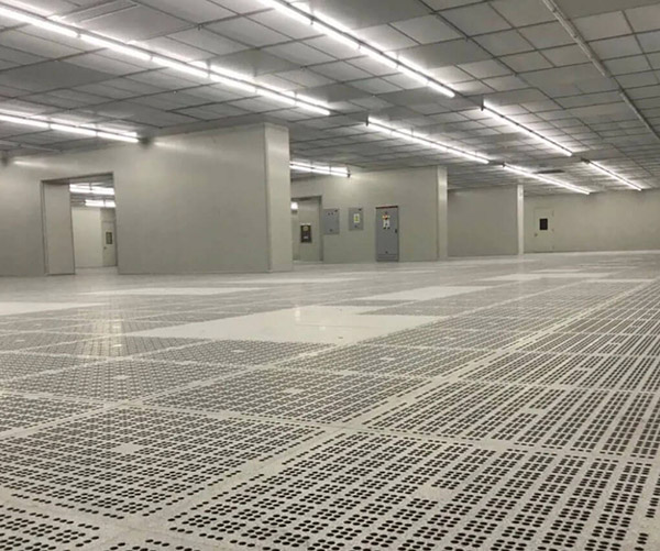
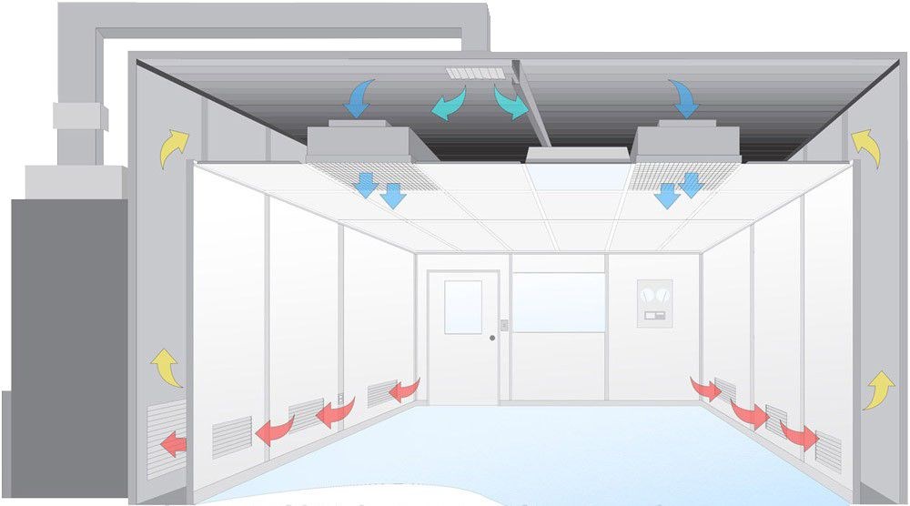
According to the specification
"Test Method for Suspended Particles in Clean Rooms (Areas) of Pharmaceutical Industry" GBIT 16292-2010
"Technical Specification for Clean Operating Room Buildings in Hospitals" GB50333-2013
"Design Specification for Clean Rooms" GB50073-2013
"Construction and Acceptance Specification for Clean Rooms" GB 50591-2010
"Design Specification for Clean Rooms in Electronic Industry" GB50472-2008
"Experimental Animals Environment and Facilities" GB 14925-2010
"Clean Rooms and Related Controlled Environments Part 3: Test Methods" GB/T25915.3-2010/ISO14644-3:2005 Good Manufacturing Practice for Pharmaceuticals" (revised in 2010)
"Test Method for Clean Rooms (Areas) of Pharmaceutical Packaging Materials Production Plants" YBB00412004-2015
"Test Method for Floating Bacteria in Clean Rooms (Areas) of Pharmaceutical Industry" GB/T 16293-2010
Test Method for Settling Bacteria in Clean Rooms (Areas) of Pharmaceutical Industry GB/T 16294-2010 Technical Specification for Building of Laboratory Animal Facilities GB 50447-2008
Laboratory Animal Environment and Facilities GB 14925-2001
Guidelines for Pharmaceutical Production Verification (2003 Edition)
The importance of system debugging in clean rooms is reflected in the following aspects
1.Discover and solve problems in equipment, facilities, control, and processes to put the clean room into normal operation; discover problems and correct design and installation defects.
2.Achieve system design goals, that is, all indicators of internal environmental parameters of the clean room meet the design requirements; the most important guarantee for ensuring design quality.
3.Reduce operating costs as much as possible under the premise of meeting the design requirements of various control parameters; ensure that the system operates in a low-consumption and energy-saving state.
Equipment performance measurement and adjustment
Be familiar with the relevant technical documents and drawings of the air conditioning system, indoor and outdoor air calculation parameters, Air volume load, temperature and humidity control accuracy requirements, etc. The process debugging personnel will go deep into the site together with the design, construction and construction units to find out where the installation quality of the air conditioning system is unqualified, find out where the construction does not conform to the design, record it in the defect list, and modify it within the deadline: prepare the instruments, meters and necessary tools required for debugging and related record matters: After the debugging of each sub-project is completed, the comprehensive performance of the air conditioning system is measured to determine whether the comprehensive indicators of the system linkage operation meet the design requirements. If not, further adjustments should be made during the measurement; the clean room is tested for cleanliness, temperature, humidity and static pressure. If it does not meet the requirements, further adjustments are required.
Implementation and debugging content
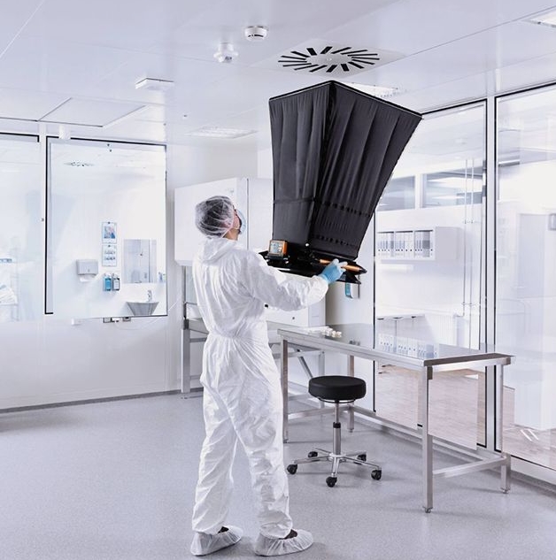
1. Detection of air volume of each air outlet in the room, total air volume of the room, total air volume of the system and conversion of room ventilation times: Use Air volume tester to adjust and detect the air volume of each air outlet, then add up the air volume of all air outlets in each room to get the air volume of each room, and then add up the air volume of each room to get the total air volume of the system. Divide the air volume of each room by the volume of the room to get the ventilation times of the room. After testing, the air volume of each air outlet, the total air volume of the room, the total air volume of the system and the ventilation times of the room must meet the design requirements, standard: total air volume: 0~20%; air volume of each air outlet: +15%; fresh air volume: +10%.
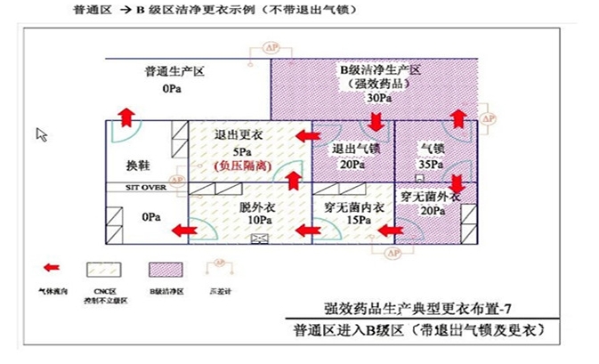
2. Static pressure difference detection:Static pressure difference measurement should be carried out after the entire connected Clean Room system is turned on and runs stably. All doors should be closed tightly. The pressure measuring tube should be sealed as much as possible. The tube should be extended from the soft pad under the door as much as possible. If the door is opened, the pressure difference will drop. The measurement sequence should start from the room with the highest design pressure and measure to the low-pressure room in turn. In terms of clean level, it should be measured from the highest level clean room to the lower level step by step. Considering that the pressure difference between clean rooms of different levels is actually small, the accuracy of the micro differential pressure meter has higher requirements. Not less than 2.0Pa. Standard: 25Pa between different levels and indoor clean and non-clean areas (new version of GMP ≥ 10Pa); clean room and outdoor should be 210Pa.
3. Indoor cleanliness detection: The number of
sampling times for each point is not less than 3 times, and the number of
sampling times for each point can be different. Conditions: air volume, positive
pressure adjustment element; indoor cleaning and cleaning as required,
biological clean room should be disinfected as required, and sufficient
pre-cleaning (air blowing) time. No more than two people wearing clean clothes
should enter, and try to be downwind. Minimum number of sampling points.
| Cleanliness | |||||
| area(m2) | |||||
| 100class 2-3 | 1000class 2 | 10000class 2 | 100000class 2 | ||
| <10 | |||||
| 10 | 4 | 3 | 2 | 2 | |
| 20 | 8 | 6 | 2 | 2 | |
| 40 | 16 | 13 | 4 | 2 | |
| 100 | 40 | 32 | 10 | 3 | |
| 200 | 80 | 63 | 20 | 6 | |
| 400 | 160 | 126 | 40 | 13 | |
| 1000 | 400 | 316 | 100 | 32 | |
| 2000 | 800 | 633 | 200 | 63 | |
Detection of indoor floating bacteria and settling bacteria
The indoor floating bacteria measurement point and
cleanliness measurement point can be the same; sampling must be carried out
according to the steps described in the instrument manual,special attention should be paid to disinfection and
sterilization of the instrument before testing.
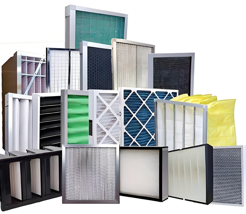
leak detection of high-efficiency Air Filters after installation
For high-efficiency filters installed at the end of the air supply and exhaust, the scanning method should be used to detect leaks on the filter installation frame and the entire cross-section. When detecting leaks, place the sampling port 2cm~3cm away from the surface of the filter to be tested, move at a speed of 5mm/~20mm/s, and scan the entire cross-section, head glue and installation frame of the filter to be tested. Standard: When the reading is greater than 0.01% of the upstream aerosol concentration, there is a leak.
Temperature and relative Humidity detection
Before measuring the indoor air temperature and relative humidity, the purification air conditioning system should have been running continuously for at least 24 hours. For places with constant temperature requirements, according to the requirements for the temperature and relative humidity fluctuation range, the measurement should be carried out continuously for 8~48 hours, and the interval between each measurement should not exceed 30 minutes. According to the temperature and relative humidity fluctuation range, the corresponding instrument with sufficient accuracy should be selected for measurement.
Indoor measuring points are generally arranged at the following locations:
Supply and return air outlets
Representative locations in the constant temperature working area (such as arranged around the process equipment or arranged at equal distances)
Center of the room (for systems without constant temperature requirements, temperature and humidity are only measured at this point)
Sensitive components. Standard: The temperature of clean rooms with air cleanliness levels A, B, and C should be 20℃~24℃, and the relative humidity should be 45%~60%; the temperature of clean rooms with air cleanliness level D should be 18℃~26℃, and the relative humidity should be 45%~65%6.
Illumination detection
Indoor illumination must be carried out after the room temperature has stabilized and the light output of the light source has stabilized.
Clean room illumination only measures general lighting except for special local lighting.
The measuring point plane is 0.8m above the ground and is arranged at a spacing of 1m~2m. The measuring point of a room within 30m2 is 0.5m away from the wall, and the measuring point of a room exceeding 30m2 is 1m away from the wall. It can be synchronized with the cleanliness measurement point, and the drawing and recording can be done. Standard: The general lighting value of the main studio should be 300lx; the illumination value of the auxiliary studio and corridor should not be less than 150lx.
Noise detection
The noise measuring instrument is a sound level meter with an octave analyzer. Generally, only the value of the A sound level is measured, and the octave sound pressure level is measured when necessary. The measuring point is 1.1m above the ground. For clean rooms with an area of less than 15m2, only one point in the center of the room can be measured; for rooms with an area of more than 15m2, in addition to one point in the center of the room, four diagonal points should be measured (as shown in the figure above), 1m away from each side wall, and the measuring point should face each corner; the height of the measuring point is 1.1m from the ground. Standard: According to the specification requirements: turbulence ≤60dB (A); parallel flow ≤65d (A).
Airflow pattern test
Measuring point location:
vertical unidirectional flow, four sections should be measured: longitudinal,
transverse and two horizontal sections 0.8 and 1.5m from the ground. Horizontal
unidirectional flow: five cross-section longitudinal sections, the horizontal
plane of the work area, the center of the room and the section 0.5m away from
the air outlet of the sender. Non-unidirectional flow: three cross-sections, the
longitudinal and transverse sections of the center of the representative air
outlet and return outlet, and the horizontal plane at the height of the work
area. Measurement point spacing: 0.2~1m Method: hanging wire, smoke,
drawing.
Debugging report
1.After debugging, the data should be sorted out immediately, and the data calculation should be accurate and reliable. Generally, at least one person should calculate and one person should proofread.
2.Analyze the original measurement data, and make adjustments to the problematic ones, and repeat them several times.
3.If you feel ideal and satisfied with the working conditions after adjustment, you can make a final comprehensive measurement as the parameters under the new working conditions.
4.After the adjustment and measurement are fully completed, each group will write a debugging report. The debugging report should include the following:
Debugging purpose
Debugging date and specific steps
Original measurement data and data analysis
Adjustment method and process
Adjustment results
Existing problems, etc.
5.Based on the debugging reports completed by each group, the general person in charge will complete the debugging report of the entire project and archive it for record.
 +86 18186671616
 Jason@cleanroomequips.com
 MENU
MENU
