+86 18186671616
 Jason@cleanroomequips.com
 MENU
MENU

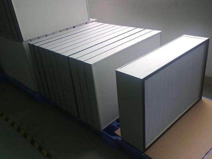
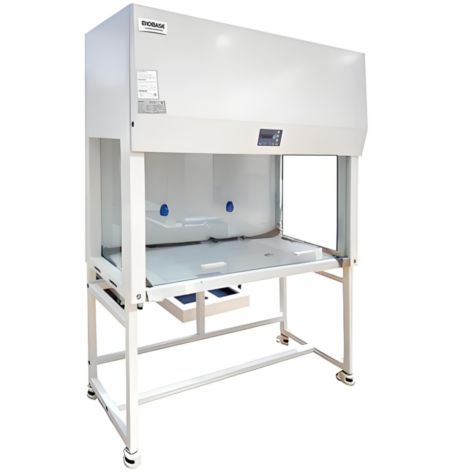
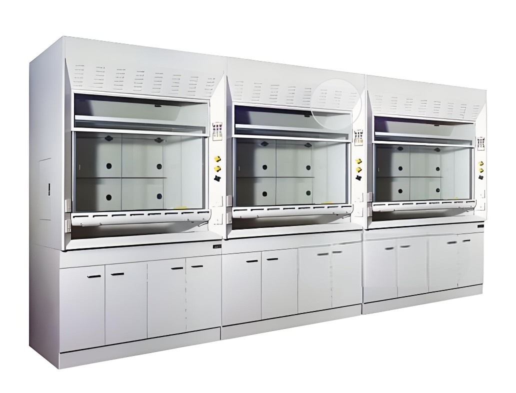
Leakage detection of high-efficiency filters

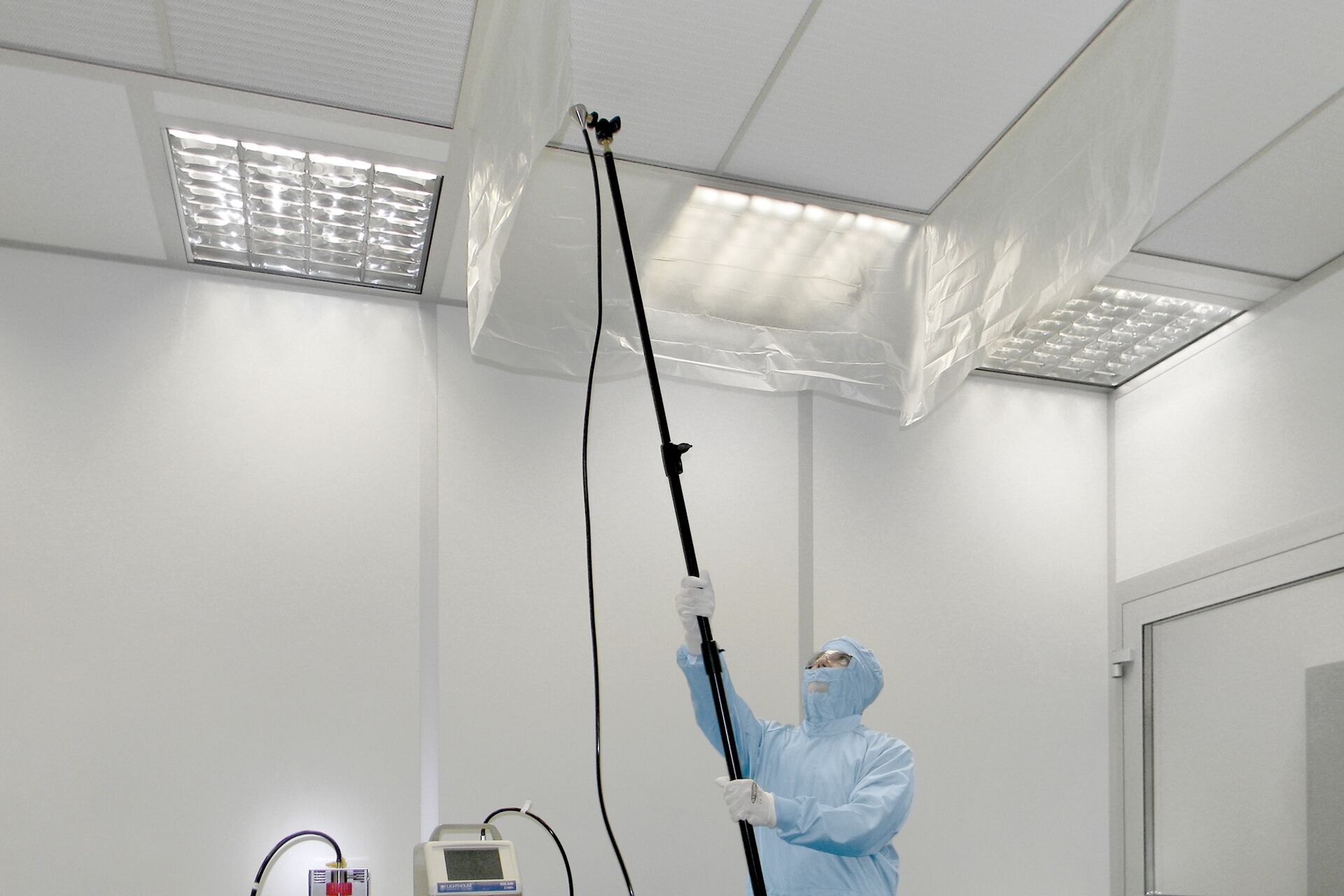
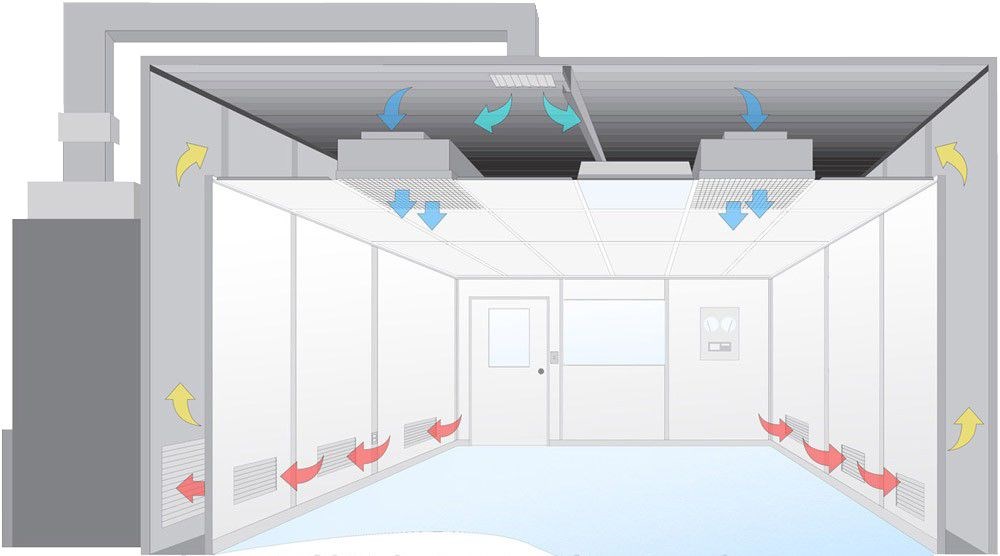
(Figure 1: Leak detection of high efficiency filter)
1. Description
The leakage test of high-efficiency filters should be the most complex and time-consuming measurement item in the clean room test. The purpose of the leakage test is to confirm.
a. The material of the filter is not damaged.
b. Proper installation. The filter must of course undergo a leakage test before leaving the factory, but it is difficult to ensure that it is completely intact during the transportation and installation process, and the importance of the filter is above all else, so a scan must be done after installation to confirm that there is no leakage in the filter material. In addition, if the installation is not appropriate, particles will leak into the clean room vents from the frame. Even if it is an FFU system, there is negative pressure on the ceiling.
The test methods are:
Aerosol photometer test method,
Particle counter test method,
Full efficiency test method,
External air test method. The latter two are rarely used now.
2. Methods
a. Aerosol photometer test method
The aerosol photometer test method is the earliest test method, but because of its excellent effect, it is still used today. Aerosol photometer is a type of particle counter, which also uses vertical projection technology, but after scanning the particles in the air sample, it gives the overall intensity of the particles, not the number of particles. DOP is an oily chemical substance, and now it is replaced by PA0. After pressurization or heating atomization, it can produce sub-micron particles, which can be used to simulate the particles in the clean room, so it is used as verification particles.
b. Particle counter test method
In the Semiconductor industry, DOP/PAO and aerosol photometers were also used in the early days, but with the increase in manufacturing precision, oily challenge particles are gradually not allowed to be used in clean rooms. Therefore, dry dust is used as challenge particles, which are applied upstream and then scanned downstream with particle counters to find leaks. The basic concept is exactly the same. After scientists have studied the results step by step, they found that PSL is the most widely used standard particle because the particle size and concentration of the particles can be controlled.
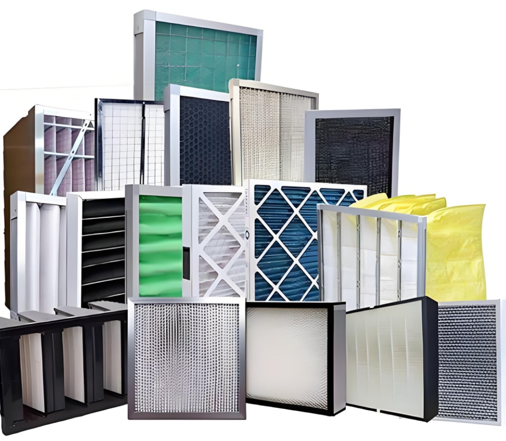
PAO/DOP filter leak detection
1. Description
The aerosol photometer test method is the earliest test method, but because of its very good effect, it is still used today. Aerosol photometer is a type of particle counter that also uses laser technology, but after scanning the particles in the air sample, it gives the overall intensity of the particles, not the number of particles. DOP is an oily chemical that can produce sub-micron particles after pressurization or heating. It can be used to simulate the particles in the clean room, so it is used as a verification particle.
The definition of leakage is to leak out one ten-thousandth of the upstream concentration. Since the aerosol photometer can directly display the ratio of the upstream and downstream particle concentrations, it is very convenient to scan the filter. Because of its accuracy and reliability, the U.S. Food and Drug Administration (FDA) stipulates that within its jurisdiction (food processing sites and medical and pharmaceutical sites), all filter leakage tests must use DOP and aerosol photometers.
 Test - Shan International")
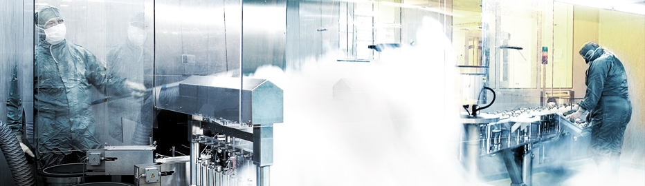
(Figure 2: PAO/DOP filter leak detection)
2. Test Instruments
This test method uses an aerosol photometer and an aerosol generator. The display of the aerosol photometer is analog and digital, and must be calibrated once a year. There are two types of particle generators. One is an ordinary particle generator that only requires high-pressure air, and the other is a heated particle generator that requires high-pressure air and power. The particle generator does not need to be calibrated.
Three. Test method:
The steps of the filter leakage test are generally to release particles and check the concentration, scan the filter and frame to find leaks, replace or repair, and retest. The steps are as follows
Record the number of filters on the drawing and number them.
Make sure the air conditioning system is operating normally and can be tested. The wind speed and air volume must be adjusted and balanced.
Use an aerosol generator to release challenge particles upstream to inject PAO into the upstream of the filter. The particle concentration is about 10 to 20 micrograms of PAO per liter of air. The more particles there are, the easier it is to find a leak, but there is little difference after exceeding 50 micrograms, and it is difficult to use if it is less than 10. The particle concentration can be roughly calculated using the air volume, and then confirmed using an aerosol photometer.
After the upstream particle concentration is confirmed, the surface of the French net can be scanned to find leaks. If necessary, the French net can be covered with plastic curtains to ensure the accuracy of the test.
Scan the surface of the filter. The scanning path can be from outside to inside or along the long/short side.
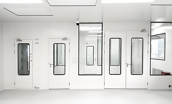
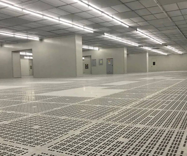
Cleanliness test

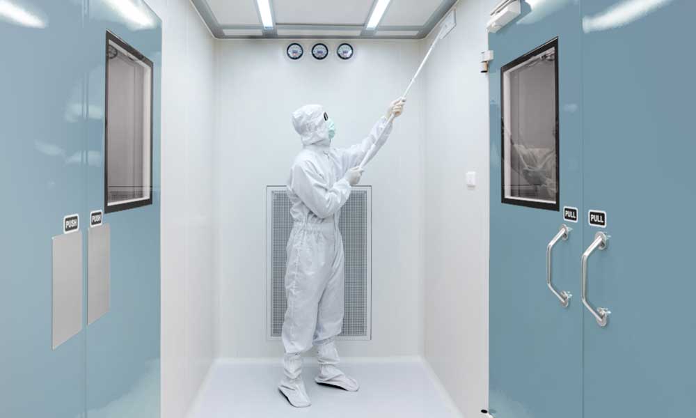
(Figure 3: Cleanroom cleanliness test)
1. Description
Cleanliness test is the core of clean room performance test. Airflow test, pressure test, and leakage test are only to confirm that the cleanliness of the clean room is not affected by external factors. Therefore, cleanliness test is placed after the above tests are passed. After the cleanliness test is completed, all performance factors related to dust fallout are tested. Other tests have little effect on cleanliness or belong to other environmental tests.
2. Test Instrument
Cleanliness test uses a particle counter. The instrument must be calibrated and still within the validity period. When submitting the report, a qualified calibration document must be attached. As for what equipment should be used, it depends on the owner's specifications. Generally, in the industry, particle counters are selected in the following ways.
Class 1000 or higher: 0.5um
Class 100: 0.3um, 0.5um
Class 1 to Class 10: 0.1um
If the particle size range required by the owner exceeds the range of a single particle counter, two particle counters should be used. There are few cubic meter particle counters on the market, so if the cleanliness of the clean room is based on ISO, the results must be converted. Unit conversion does not affect the calculation procedure of the upper limit.
3. Test steps
Make sure that the test adjustment and balancing of the air conditioning system have been completed, the wind speed and leakage tests of the filter have been completed, and the damaged parts have been repaired.
Confirm the test location and number of test points.
Sampling time: The sampling time for each point varies according to the grade and particle size. If the sampling time is less than one minute, it shall be one minute.
The test locations should be evenly distributed in the clean room, avoiding the vicinity of a large number of particles, and the test instrument should be supported by an appropriate stand and not handheld.
The number of measurement points is calculated using the formula (same as 209E).
4. Acceptance criteria
There are two acceptance criteria for cleanliness. The first is that the average particle measurement value at each point must be lower than the specified value. The second acceptance criterion for cleanliness is that if any compartment needs to use the upper limit of confidence analysis, the analysis value must also be less than the specified value.
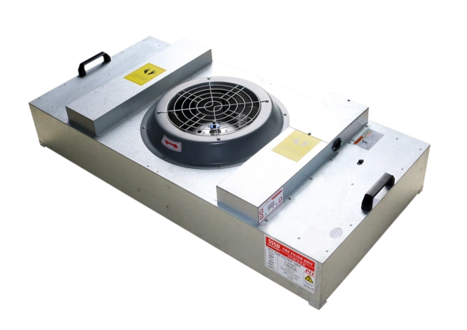
Wind speed and balance test
1. Test purpose
Airflow is the most important factor in controlling cleanliness, temperature and humidity, and it also has some impact on noise. Therefore, wind speed measurement is always the first step in the clean room test. The purpose of wind speed measurement is to confirm that the airflow sent by the filter meets the design specifications, and secondly to confirm the uniformity of the airflow. In some cases, due to site restrictions, the indoor ventilation volume must also be converted by multiplying the wind speed by the outlet area.
Many single-flow clean rooms are designed as vertical laminar flows, so wind speed uniformity is very important. Only uniform vertical laminar flows can effectively eliminate particulate pollution. For non-single-flow clean rooms, since the concept of particle control is dilution, not immediate elimination, the ventilation volume is generally far more important than wind speed. However, it must be noted whether it is the filter wind speed measurement or the clean room indoor wind speed measurement.
2. Instruments used
The HEPA/ULPA filters used in clean rooms mostly control the airflow speed within 0.5m/, so the anemometer used must be a low-speed type. The filter air velocity can be measured using a single-point anemometer such as an Electronic pressure gauge in combination with a Pitot tube or a hot-wire anemometer. A multi-point anemometer such as a Shortridge Velgrid 16-point anemometer can also be used. Vane anemometers are usually not used in clean rooms due to their different application ranges.
3. Test steps
Record the filter size, quantity and number on the drawing.
The sampling point is located 75-150mm below the filter.
Under each filter, if a single-point anemometer is used, take one point for every 1 square foot; if a multi-point anemometer is used, take one point for every 4 square feet.
Each measurement point must be averaged for 5 seconds.
Analyze all wind speeds according to the acceptance criteria, calculate the average, standard deviation, relative standard deviation, and mark the unqualified test points.
Record all original values and the values after analysis. It is important to pay special attention to the anemometer during sampling when testing non-single-flow clean rooms, so as not to affect the accuracy.
4. Data Analysis
Wind speed measurement is simple, but uniformity must be determined by data analysis. Uniformity is represented by relative standard deviation, and the calculation steps are as follows
Average: 2. Standard deviation

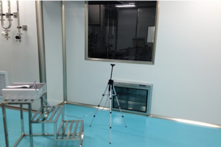
(Figure 4: Clean room wind speed and balance test)
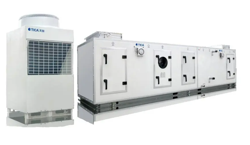
Air volume and balance test
1. Description
Air volume measurement calculates ventilation, typically in non-single-flow clean rooms and HVAC systems. When air hoods can't be used, wind speed multiplied by effective area estimates air volume, though accuracy is poor for return and exhaust outlets. Air hoods measure supply and return air effectively.
2. Test Instrument
The air volume measurement should use a gas hood (Flow Measuring Hood). The measurement range of the gas hood is 15~2500 cfm, and the accuracy requirement is +3% of the reading. Since the air hood itself will produce pressure loss, its shape is very important, and the original air hood should be used as much as possible. If it is necessary to make the hood by yourself, you should pay attention to the smooth air flow and make a detailed comparison. The calibration of the air hood is very important. The host must be calibrated together with the hood to obtain an accurate calibration value.
3. Test steps
Record the size and quantity of the net on the drawing and number them.
Use an air hood of the appropriate size to completely cover the air outlet, then measure and record.
Analyze all air volumes according to the acceptance criteria, calculate the average, standard deviation, relative standard deviation, and mark the unqualified test points.
Record all original values and the values after analysis.
4. Data analysis
The calculation of air volume uniformity is the same as that of wind speed, and is represented by relative standard deviation. The calculation steps are as follows.
Average: Take the arithmetic average of all wind measurement values.
Standard deviation: Calculate the standard deviation of all wind measurement values.
Differential pressure test

(Figure 5: Clean room pressure difference test)
1. Description
The purpose of pressure measurement is to confirm the pressure setting of the clean room air conditioning system. It is common sense to maintain a certain positive pressure in the clean room to maintain cleanliness. In the old version of 209, there was a recommended value for positive pressure, but it was later cancelled. The current common positive pressure value is about 10 to 25 Pascal. The timing of pressure measurement should be immediately after the wind speed, air volume, parallelism and other tests directly related to airflow are completed.
2. Testing Instrument
Pressure measurement can use an inclined tube pressure gauge, a pointer pressure gauge, or an electronic pressure gauge. In short, as long as the measurement range and accuracy meet the requirements, it can be used. The accuracy requirement of the pressure gauge is +5% of the reading. The measurement range depends on the pressure design value. Generally, 0~5mm Ag (050 Pascal) can cover the measurement of indoor and outdoor pressure differences. The instrument can only be used after it has passed the calibration and is still within the validity period. The qualified calibration documents must be attached before the test and when the report is submitted.
3. Test steps
The pressure can only be tested after the wind speed, air volume, air flow and other tests are completed, and the exhaust and MAU must be fully operational.
All doors and openings must be closed. The outdoor atmospheric pressure is assumed to be 0.0mmAg gauge pressure. 1113. Measure the pressure difference between the clean area and the adjacent secondary clean area, then measure the pressure difference between the room and the Gowning room, and finally measure the pressure difference between the Gowning room and the outside.
The recommended pressure difference value is 5~12Pa, and there is no mandatory requirement.
Record all values.
Temperature and humidity detection
1. Description
Temperature and humidity measurements ensure indoor conditions are within range, classified as Level 3 tests since they don't affect particle control. Measurements include general (real-time) and advanced (long-term monitoring) to suit varying environmental requirements in clean rooms.
2. Test instruments
Common temperature and humidity instruments include electronic thermometers and hygrometers. Both general and advanced measurements require similar accuracy: temperature (0-100℃, ±0.2℃) and humidity (10-95%, ±2%). Calibration documents must accompany tests if instruments are within validity.
3. Test procedures
Confirm that the air conditioning system has been installed, tested, adjusted, and balanced. Testing, adjusting, and balancing the air conditioning system can balance the air volume and water volume to meet the design requirements and provide the correct operating environment for temperature and humidity control. Therefore, the system must be balanced before testing.
According to the floor plan, list various temperature and humidity requirement areas, and make the system reach normal operating conditions. The system should operate for at least 24 hours under automatic temperature and humidity control.
The number of test points is at least one point for each room, and at least one point for each temperature and humidity control area. For example, each Dry Coil control range must be measured at one point, and the measurement height is 1.00m on the (elevated) floor.
Place the temperature and humidity sensors in the same position and start recording after stabilization.
Illuminance test

(Figure 6: Illumination test)
1. Preparation before test
All openings in the clean room must be sealed and airtight.
Before the test, the air conditioning system should have been tested, adjusted, balanced, and operated continuously for more than 24 hours. The clean room environment must be cleaned.
2. Test purpose
This test action is to confirm whether the clean room lighting system meets the design requirements.
3. Test instrument
Professional illuminance meter.
4. Test steps
The light source in the clean room should be used for at least 100 hours and should be lit for more than 2 hours before the test.
Confirm the test point and configuration drawing number.
Fix the illuminance meter at a height of 1.2m from the floor, and measure and record for 10 seconds after the value stabilizes.
Noise test

(Figure 7: Clean room noise test)
1. Test preparation
Completion drawing (first version) and relevant specifications are confirmed.
All openings in the clean room must be sealed and airtight.
Before the test, the air conditioning system should have been tested, adjusted, balanced, and operated continuously for more than 24 hours, and the clean room environment device should be cleaned.
2. Test purpose
This test action is to confirm whether the clean room noise meets the design requirements.
3. Test instrument
Professional noise meter.
4. Test location
Take 1 point as the measurement point for every 40m2, and increase the number of test points locally according to the owner's requirements.
5. Test steps
All air conditioning equipment and public equipment in the clean room are in operation.
Confirm the test point and configuration diagram number.
Fix the illuminance meter at a height of 1.2m from the floor, and record the maximum value after 10 seconds of height measurement.
Airflow direction detection

(Figure 8: Clean room airflow direction detection)
1. Test purpose
The purpose of parallelism measurement is to observe the movement pattern of airflow in the working area, and at the same time, observe the influence of instruments and equipment on airflow. Parallelism measurement should be carried out after the wind speed and uniformity of the airflow are tested and passed. If it is carried out too early, correct data may not be obtained.
2. Test method
Parallelism measurement typically involves visual observation using smoke, water mist, or lightweight thin wire. While smoke and mist effectively reflect airflow, they can pollute clean rooms. Lightweight polymer Flo-Viz is also used, measured against a plumb line for accuracy.
3. Test instrument
Stand
Plumb line
Flo-Viz thin wire
Airflow direction detector
4. Test steps
Use a bracket to set up a vertical line as a reference line.
Suspend the thin wire in the room and let it droop naturally. The thin wire will drift with the air flow. Calculate the offset angle = tan-1 (suspension line? displacement/1220).
Measure 1 point per 3mx3m area. If smoke is used, the method is very similar, that is, release smoke under the filter, then move the upper end of the plumb line to contact the smoke, treat the red line as smoke, and then calculate the angle.
Floor conductivity detection

(Figure 9: Cleanroom floor conductivity test)
1. Test introduction
Conductivity can be regarded as the ease of current flowing through or around an object (relative ease), and the reciprocal of resistance is conductivity
2. Measurement purpose
Measure the resistance between points on the floor (Floor Point to Point) and the resistance between the floor and the ground (Floor to Ground).
Point to Point detection process.
Temperature and humidity must have been tested and adjusted to pass.
Two electrodes are required for each set of data.
The open circuit voltage of the resistance meter is 500 ohms, and the internal resistance is at least 100,000 ohms.
At least 5 sets of data are measured for each clean room and the average value is taken.
3. Floor to Ground Testing process
This is to measure the conductivity between the Clean room floor and the grounding electrode.
The temperature and humidity must have been tested and adjusted to be qualified.
The electrodes at both ends of the resistance meter, one is connected to the floor, and the other is connected to the nearest building column.
The measurement position is specified by the Owner, there should be 20 positions, take 5 different points for measurement at each position, and then take the average value.
The average resistance should be less than one million ohms.
All raw data and average values must be listed in the report.
Self-cleaning ability test
1. Test purpose
Confirm how long it takes to restore the cleanliness level before the release of particles in the clean room.
2. Test instrument
Particle tester (brand MET ONE), model: 3313, 2100, particle releaser.
3. Test location
Select any measurement point, and confirm the test point with relevant personnel.
4. Test steps
Before the test begins, ensure that the clean room air conditioning system is operating normally for more than 24 hours to allow the clean environment to reach a stable level.
Place a particle counter at the measurement point, do a particle cleanliness test first, record the number of 0.3um particles in the air per cubic foot of the room, test continuously for several minutes, wait for a stable data, then turn off the power of the entire air conditioning system in the room.
Release the particles in the room, so that the particles in the non-clean area outside can make the 0.3um particle concentration in the entire clean room reach 10 or 100 times the previous concentration. At this time, start the air conditioning system again to make it operate normally, and test the time required for the particle concentration in the clean room to return to the previous level.

(Figure 10: clean room static electricity detection)
Electrostatic detection
1. Test purpose
The problem of static electricity is not only in the semiconductor industry, but also in other industries. If there is static electricity on tiny substances, it will become a very difficult problem to deal with, because it becomes very difficult to transmit. In addition, in the clean room, if the surface of the object has static electricity, it is easy to attract dust and cause pollution. The purpose of the static electricity test is to measure the content of positive and negative ions in the air, and the residual surface voltage of the object in the airflow field can be simulated based on this data.
2. Test procedure
Measure the positive and negative ion content in the air at a height of 813 mm from the ground in the clean room. The unit is the number of ions per cubic centimeter. Number of measurement points: 10, or determined by the owner.
Perform residual voltage test at the same location.