+86 18186671616
 Jason@cleanroomequips.com
 MENU
MENU
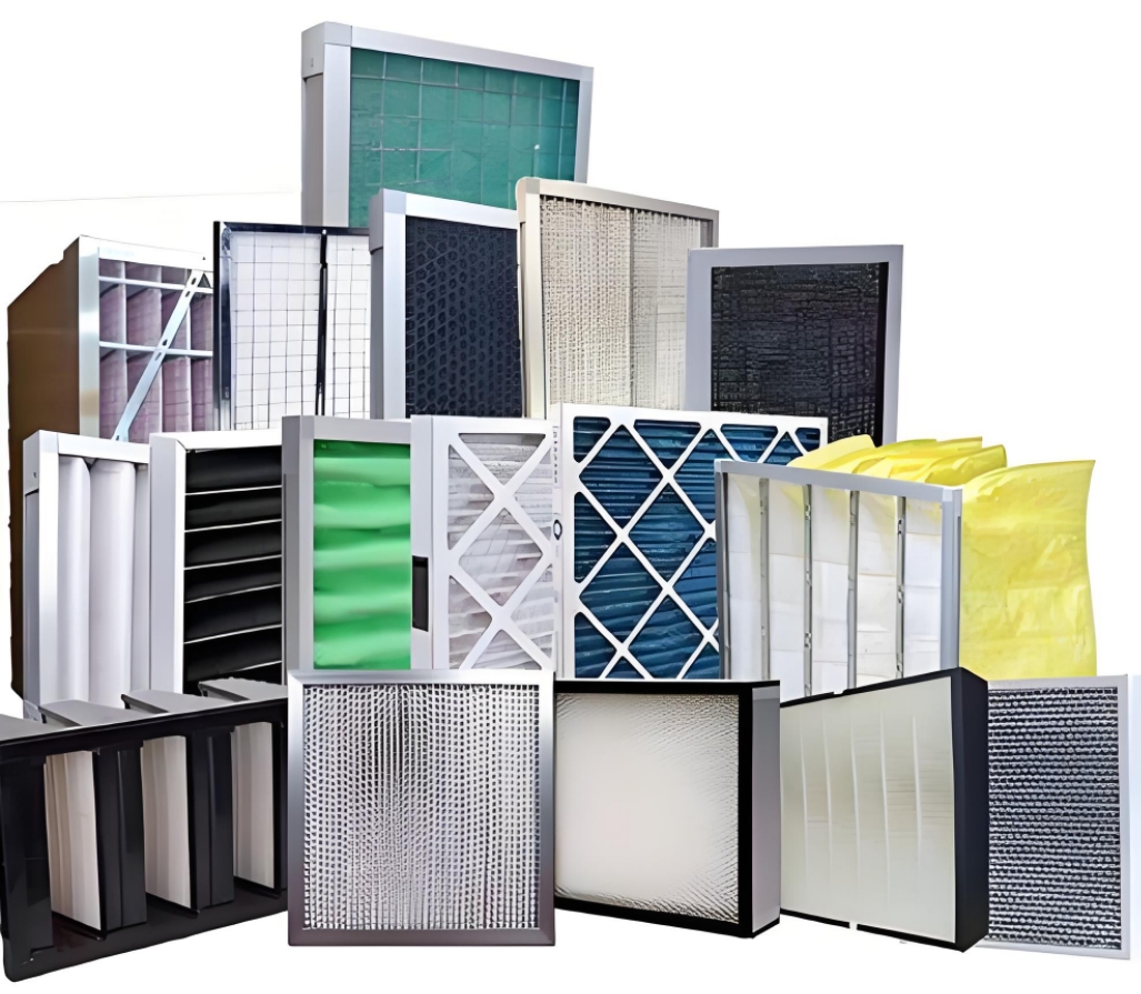
Scope of application
This procedure is applicable to the integrity test of high-efficiency filters (commonly known as high-efficiency filter leak detection).
Principle of high-efficiency filter leak detection
The concentration of upstream and downstream particles is measured by an aerosol photometer to obtain the size of the leakage rate.
Instruments and equipment
Aerosol generator
Aerosol photometer
Air supply hose
Consumables: PAO (EMERY 3004)
What is the price of high-efficiency filter leak detection?
High-efficiency filter leak detection is charged according to the number of high-efficiency filters. The filters are divided into liquid tank filters and partition filters. Generally, cold detection is more expensive and hot detection is more favorable. For specific quotes, please contact Danting Technology Sales Consultant.
high efficiency filter leak detection cycle
High efficiency filter leak detection cycle is generally carried out once a year according to GB regulations.

High efficiency filter integrity test method
Operation steps
1. Pre-inspection
a. Aerosol generation
① For non-laminar flow area
Turn off the HVAC fan.
Remove the medium efficiency filter.
Place the aerosol generator in the negative pressure section of the unit.
② For laminar flow unit
The smoke generating position is close to the return air outlet, the fan air inlet or the special aerosol smoke generating port.
b. Aerosol concentration determination
Find the test hose or test hole in front of the high efficiency filter. If there is no test hole, the upstream concentration can be tested at the pressure gauge of the air conditioning unit.
Adjust the internal parameters of the photometer to 100.
c. High efficiency filter integrity test (high efficiency leak detection)
Scan the surface and frame of the HEPA.
For spherical structures, directly connect the hose or hole of the high-efficiency filter to the downstream channel of the photometer.
2. High-efficiency filter integrity test (high-efficiency leak detection) test procedure
a. Generate aerosol
Turn on the power supply and raise the temperature to 400 degrees Celsius.
Connect nitrogen and check that the nitrogen supply pressure is 50psig (3.45bar).
b. Turn on the aerosol generation button and wait for a few minutes for the aerosol to reach the terminal filter.
c. High-efficiency filter integrity test upstream concentration test
d. Connect the scanning probe to the upstream concentration test hole.
Then keep the cursor on "upstream 100% concentration detection" and press "Confirm"; observe the upstream concentration value, adjust the reading between 20-80, and record the reading after the reading stabilizes.

e. High-efficiency filter integrity test downstream concentration detection.
Connect the scanning probe to the downstream concentration test hole.
Adjust the cursor to "Use internal reference value"
Press the "Confirm" key to adjust the parameter value to the measured upstream concentration value.
Scan the filter surface and frame, about 3cm away from the filter surface.
The reciprocating scanning speed Sr of the sampling head is about 15/Wp. When using a 3cm*3cm square sampling head, Sr= 5cm/s; using a 5cm*1cm rectangular sampling head, Sr=3cm/s. (Sr is the scanning speed, and Wp is the width of the sampling head perpendicular to the scanning direction).
f. High efficiency filter integrity test upstream concentration review.
Connect the upstream concentration test tube to the upstream concentration test hole.
Then keep the cursor on "Upstream 100% Concentration Detection" and press "Confirm"; observe the upstream concentration value. The upstream concentration should not change over time by more than ±15% of the average measured value.
g. End
Turn off the aerosol button.
Nitrogen continues to pass through the aerosol generator for about 30 seconds.
Turn off N2.
Turn off the power.

High efficiency filter integrity test operation steps
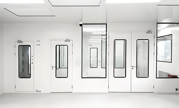
Local laminar flow/room class 100 (high efficiency leak detection)
Non-laminar clean room (high efficiency leak detection)
A. Remove the laminar flow hood.
B. Rated Wind speed determination.
The measurement point is about 150-300mm away from the filter outlet surface.
The number of test points is the square root of 10 times the test area, and there are no fewer points, at least 1 point on each fan outlet surface.
Average wind speed range: 0.45 m/s±20%
Rated Air volume measurement.
Use Air volume hood to test air volume.
The upper opening of the air volume hood should completely cover the filter or diffuser.
C. Aerosol generation location: return air port, fan air inlet or smoke hole.
There is no filter between the aerosol generator and the high-efficiency filter or it has been removed.
D. Aerosol generation.
Set temperature, air supply pressure and aerosol quantity.
E. Photometer setting.
Aerosol concentration adjustment.
F. Leak detection
Scan the entire filter and install all frames and joints.
Sampling head scanning rate ≤5cm/s (3cm*3cm).
Sampling head scanning rate ≤3cm/s (5cm*1cm).
The distance between the sampling head and the filter surface is ≤3cm.

Leak detection
Scan all structural components:
Between the bracket and the building
Between the bracket and the filter frame
The entire filter
Between the sealing strip, frame and bracket
The sampling head scanning rate is ≤5cm/s (3cm*3cm)
The sampling head scanning rate is ≤3cm/s (5cm*1cm)
The distance between the sampling head and the filter surface is ≤3cm
G. High-efficiency filter leak detection standard
Leakage rate ≤0.01%
High-efficiency filter integrity test standard (high-efficiency filter leak detection standard)
ISO 14644-3;2005
GB/T25915.3-2010
GB50073-2013
JG/T292-2010
GB50472-2008