1. General Provisions
1.1 This chapter applies to the inspection and acceptance of the construction quality of the installation of integral, assembled and unit refrigeration equipment (including heat pumps), refrigeration accessories, other supporting equipment and pipeline systems in air-conditioning projects with a working pressure not higher than 2.5MPa and a working temperature of -20~150℃.
Note: This article defines the working scope of the refrigeration system of air-conditioning projects as the installation of integral, assembled and unit refrigeration equipment, refrigeration accessories, other supporting equipment and pipeline systems with a working pressure not higher than 2.5Mpa and a working temperature of -20~150℃. Refrigeration equipment and systems such as air separation, quick freezing and deep freezing are not included.
1.2 The model, specification, performance and technical parameters of refrigeration equipment, refrigeration accessories, pipelines, pipe fittings and valves must meet the design requirements. The appearance of the equipment unit should be intact, the seal should be good, and the random documents and accessories should be complete.
Note: Air conditioning refrigeration is a complete circulation system, requiring its units, accessories, pipelines and valves to match each other and be intact. For this reason, this article specifically stipulates that their models, specifications and technical parameters must comply with the design regulations and cannot be arbitrarily replaced.
1.3 The installation of steam, fuel oil, gas supply systems and cold storage systems that are matched with refrigeration units shall also comply with the provisions of design documents, relevant fire protection specifications and product technical documents.
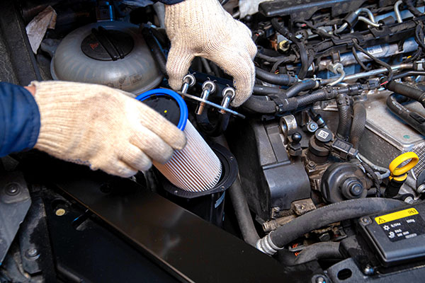
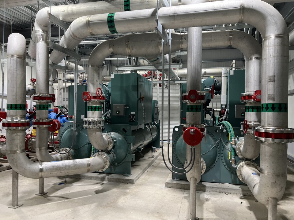
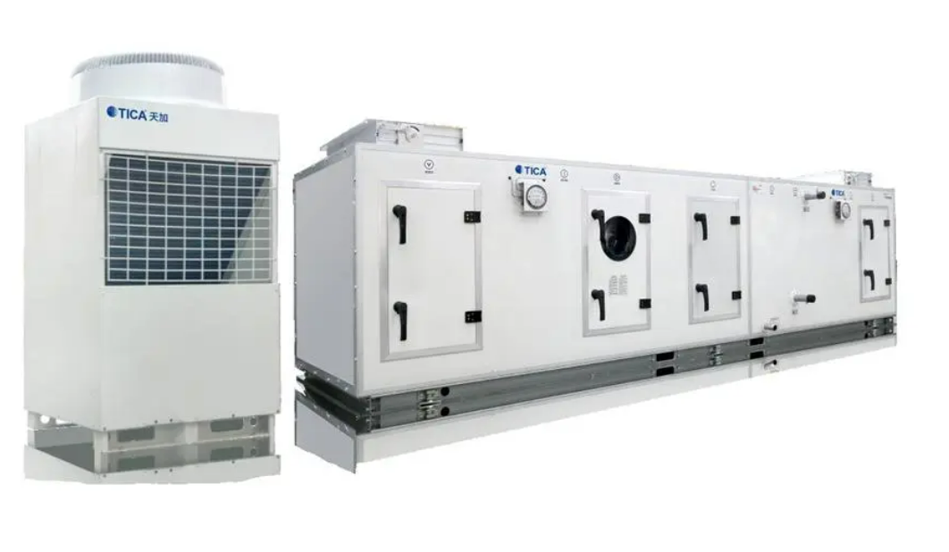
(Figure 1: Air conditioning and refrigeration system installation)
Note: Now, the power source of refrigeration units in air-conditioning refrigeration systems is no longer just a single electric energy, but has developed into a new pattern of multiple energy sources. The installation of new energy sources such as fuel oil, gas and steam for air-conditioning refrigeration equipment has great particularity. For this reason, this article emphasizes that it should be implemented in accordance with the provisions of design documents, relevant specifications and product technical documents.
1.4 The handling and hoisting of refrigeration equipment for air conditioning shall comply with the provisions of product technical documents and this specification.
Note: Refrigeration equipment is of various types and shapes, with great differences in weight and volume, and is equipped with interrelated accessories, instruments, electrical appliances and automatic control devices, etc., which have high requirements for handling and hoisting. The hoisting of refrigeration units is also one of the main processes of equipment installation. This article emphasizes that the key is to prevent the equipment from being deformed or damaged during hoisting. For the hoisting of large, high-altitude and special occasion equipment, a construction plan should be prepared.
1.5 The installation, testing, trial operation and acceptance of the refrigeration unit body should also comply with the relevant provisions of the current national standard "Construction and Acceptance Specifications for Installation of Refrigeration Equipment and Air Separation Equipment" GB50274.
Note: For the installation of the refrigeration unit body in the air-conditioning refrigeration system sub-project, this specification adopts the method of directly quoting "Construction and Acceptance Specifications for Installation of Refrigeration Equipment and Air Separation Equipment" GB 50274-1998.
(Figure 2: Transportation of refrigeration equipment)
2. Main control items
2.1 The installation of refrigeration equipment and refrigeration auxiliary equipment shall comply with the following provisions:
The model, specification and technical parameters of refrigeration equipment and refrigeration auxiliary equipment must meet the design requirements, and have product certificates and product performance test reports.
The concrete foundation of the equipment must be subject to quality handover acceptance, and can only be installed after passing the acceptance; the location, elevation and pipe direction of the equipment installation must meet the design requirements. For refrigeration equipment or refrigeration accessories fixed with anchor bolts, the placement of the pads should be correct and the contact should be tight; the bolts must be tightened and anti-loosening measures should be taken.
Inspection quantity: All inspections.
Inspection method: Check the equipment model and specifications by checking the drawings: product quality certificate and performance inspection report.
Note: This article stipulates the main control items that the acceptance of the installation quality of refrigeration equipment and refrigeration accessories should comply with.
2.2 The appearance of the direct expansion surface cooler should be kept clean and intact, and the air and refrigerant should flow in reverse; the gaps around the surface cooler and the shell should be sealed, and the condensate discharge should be unobstructed.
Inspection quantity: All inspections.
Inspection method: Observation inspection.
Note: The heat exchange efficiency of the direct expansion surface heat exchanger is related to the heat transfer conditions on both sides of the heat exchanger. When installing the equipment, the outer surface of the heat exchanger should be kept clean and the air and refrigerant should flow in reverse.
(Figure 3: Fuel system)
2.3 The equipment pipelines of the fuel system, as well as the installation, location and connection methods of the oil storage tanks and daily oil tanks shall comply with the design and fire protection requirements. The installation of gas system equipment shall comply with the design and fire protection requirements. The installation and adjustment of the pressure regulating device and the filter shall comply with the provisions of the equipment technical documents, and the grounding shall be reliable.
Inspection quantity: full inspection.
Inspection method: check, observe and check the grounding test records according to the drawings
Note: For the installation of fuel and gas system equipment, fire safety is a requirement of the pen, so the article particularly emphasizes that the location and connection method should comply with the requirements of design and fire protection and be reliably grounded according to the design regulations.
2.4 The technical data of various tightness tests and trial runs of refrigeration equipment shall comply with the provisions of the equipment technical documents. For assembled refrigeration units and units filled with refrigerant on site, it is necessary to carry out blowdown, air tightness test, vacuum test and refrigerant filling leak test, and the corresponding technical data must comply with the provisions of the product technical documents and relevant current national standards and specifications.
Inspection quantity: full inspection.
Inspection method: on-site inspection, inspection and review of trial operation records
Description: The process of various tightness tests and trial operation of refrigeration equipment is the basis for the acceptance of the quality of the equipment itself and the quality of installation, and must be taken seriously. Therefore, this article takes it as the main control item for acceptance. For assembled refrigeration equipment, the test items should comply with all the items listed in the article, and should all meet the indicators specified in the corresponding technical standards.
2.5 The installation of refrigeration system pipes, fittings and valves shall comply with the following regulations:
The model, material and working pressure of the pipes, fittings and valves of the refrigeration system must meet the design requirements, and should have a factory certificate and quality certificate.
The sealing materials of flanges, threads, etc. should be compatible with the performance of the medium in the pipe;
The refrigerant liquid pipe shall not be installed in a U shape upward. Gas pipelines must not be installed downward in a U shape (except for special oil return pipes); when liquid branches are led out, they must be connected from the bottom or side of the main pipe; when gas branches are led out, they must be connected from the top or side of the main pipe; when there are more than two branches leading out from the main pipe, the connection parts should be staggered, and the spacing should not be less than 2 times the diameter of the branch pipe, and not less than 200mm;
The slope and slope direction of the connection of the refrigerant pipeline between the refrigerator and the auxiliary equipment should comply with the design and equipment technical documents. When there is no regulation in the design, it shall comply with the regulations in the table;
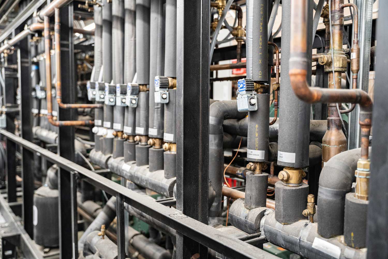
(Figure 4: Refrigeration system piping)
Compressor suction horizontal pipe (fluorine) ≥10/1000 compressor
Compressor suction horizontal pipe (ammonia) evaporator 23/1000
Compressor exhaust horizontal pipe oil separator ≥10/1000
Condenser horizontal supply pipe liquid reservoir (1~3)/1000
Oil separator to condenser horizontal pipe oil separator (3~50)/1000
Before the refrigeration system is put into operation, the safety valve shall be debugged and checked, and its opening and return seat pressure shall meet the requirements of the equipment technical documents. Inspection quantity: 20% of the total number shall be sampled, and shall not be less than 5 pieces. Article 5 Full inspection Inspection method: Verify the qualification certificate, observe, measure with a level meter, and check the adjustment records.
2.6 The fuel pipeline system must be equipped with a reliable anti-static grounding device, and its pipeline flange shall be connected with a galvanized ring bolt or jumpered with a copper wire at the flange, and the joint shall be good
Inspection quantity: full system inspection. Inspection method: Observation inspection, review of test records
Description: Static electricity sparks in the fuel pipeline system may cause great harm and must be eliminated. This article is aimed at this problem.
2.7 Non-metallic hoses shall not be used to connect the gas system pipeline to the unit. The gas pipeline shall be purged and pressure tested with compressed air or xenon, and water is strictly prohibited. When the pressure of the gas supply pipeline is greater than 0.005MPA, the implementation standard of the non-destructive testing of the weld shall be in accordance with the design regulations. When there is no design regulation and ultrasonic flaw detection is used, all inspections shall be carried out, and the quality shall be not less than Grade II.
Inspection quantity: full system inspection.
Description: The gas pipelines used in refrigeration equipment can be divided into two categories: low pressure and medium pressure. When the pressure of the access pipeline is greater than 0.005Mpa, it belongs to the medium-pressure gas system. In order to ensure the safety of use, the quality of its pipeline construction must comply with the provisions of this article.
2.8 Ammonia refrigerant system pipelines, accessories, valves and materials shall not be made of copper or copper alloy materials (except phosphor bronze), and the pipes shall not be galvanized. The pipeline welds of the ammonia system shall be radiographically inspected, with a sampling rate of 10%, and the quality shall not be lower than Grade III. In places where radiographic inspection is not easy to perform, ultrasonic inspection can be used instead, and the quality shall not be lower than Grade II.
Number of inspections: All systems are inspected.
Inspection methods: Observation inspection, review of flaw detection reports and experimental records.
Description: Ammonia is a toxic and harmful gas, but it is also a refrigerant with good performance. In order to ensure the safety of use, this article has made strict regulations on the sealing requirements for the installation of pipes and components of ammonia refrigeration systems, which must be followed.
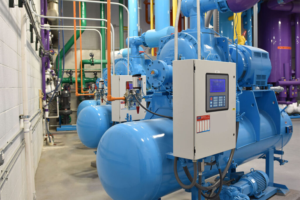
(Figure 5: Ammonia refrigerant system)
2.9 Pipeline systems that transport ethylene glycol solutions shall not use internal galvanized pipes and accessories.
Number of inspections: 20% of the pipe sections of the system shall be randomly inspected, and shall not be less than 5 pieces.
Inspection methods: Observation inspection, review of installation records.
Description: Ethylene glycol solution and zinc are prone to chemical reactions that are not conducive to the use of pipelines, so it is stipulated that galvanized pipes and accessories shall not be used.
2.10 The refrigeration pipeline system shall be subjected to strength, airtightness and vacuum tests, and must be qualified.
Number of inspections: All systems are inspected. Inspection methods: On-site supervision, observation inspection and review of test records.
Description: The refrigeration pipeline system specified in this article mainly refers to the refrigerant pipeline installed on site, including gas pipes, liquid pipes and accessories. Their strength, air tightness and vacuum tests must be qualified. This is one of the most basic control items in the construction acceptance of the refrigeration piping system.
(Figure 6: Ethylene glycol solution)
3. General items
3.1 The installation of refrigeration units and refrigeration accessories shall comply with the following provisions:
The allowable deviation of the installation position and elevation of refrigeration equipment and refrigeration accessories shall comply with the regulations.
Refrigeration units with spring vibration isolation shall be equipped with positioning devices to prevent horizontal displacement of the unit during operation.
Inspection quantity: All inspections.
Inspection method: Use a level, level, etc. to detect, measure and observe on the base or designated reference surface.
Description: Whether it is a positive displacement refrigeration unit or an absorption refrigeration equipment, they have requirements for the installation quality of the horizontality and verticality of the machine body, otherwise it will bring adverse effects to the operation of the unit. Therefore, this article stipulates its acceptance requirements.
3.2 When multiple modular chiller units are connected in parallel, the interface should be firm and the mesh should be tight and leak-proof. The appearance of the unit after connection should be flat, intact, and without obvious distortion.
Inspection quantity: All inspections,
Inspection method: Measurement and observation inspection.
Description: The modular refrigeration unit is a complete refrigeration system unit (i.e. module) composed of a refrigerator, evaporator, condenser, water pump and control mechanism according to a certain structural size and form. It can be used alone or in parallel to form a large-capacity chiller. The pipes between modules are often fixed with V-shaped clamps. This article stipulates the quality requirements for the installation and acceptance of cold water pipes, pipe components and valves.
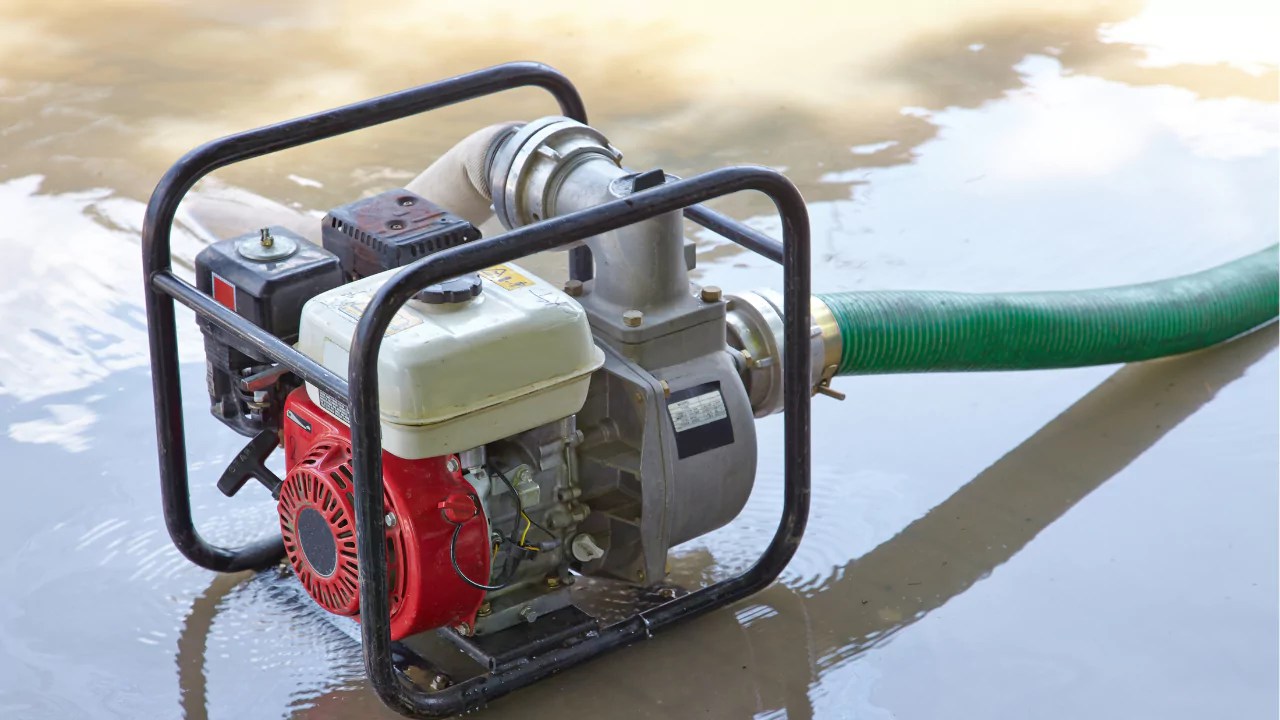
(Figure 7: Water pump)
3.3 For the installation of the fuel system oil pump and the coolant pump of the cold storage system, the longitudinal and transverse horizontality allowable deviation is 1/1000, the axial inclination allowable deviation of the two shaft cores of the coupling is 0.2/1000, and the radial displacement is 0.05 mm.
Inspection quantity: All inspections:
Inspection method: On the machine base or the specified reference surface, use a level, level, etc. to detect, measure and observe.
Description: This article stipulates the quality requirements for the installation and acceptance of the fuel pump and the coolant pump of the cold storage system.
3.4 The installation of refrigeration system pipes and fittings shall comply with the following provisions:
Pipes and fittings must be clean and dry. Copper pipe supports should meet design specifications. Separate brackets are needed for refrigerator suction and exhaust pipes.
For pipes ≤ 20 mm diameter, brackets should be outside the valve. When parallel, the suction pipe must be on the bottom.
Refrigerant pipe elbows must have a bending radius ≥ 3.5D, with diameter differences ≤ 0.08D. Avoid welded or wrinkled elbows. Branch pipes should bend into a 90° arc toward the main pipe; avoid pressed elbows with a radius < 1.5D.
Copper pipe cuts must be flat and defect-free. Allowable inclination deviation is 1% of diameter. Pipe mouths should be concentric without cracks.
Socket brazing connections require regulated plug-in depth, with expansion facing the flow direction. Misalignment at butt welds must not exceed 0.1 times wall thickness or 1 mm.
Table 1. Depth of expansion of copper pipe socket for socket welding (mm)
Copper tube specifications | DN15 | DN20 | DN25 | DN32 | DN40 | DN50 | DN65 |
Socket expansion depth | 9~12 | 12~15 | 15~18 | 17~20 | 21~24 | 24~26 | 26~30 |
3.5 The installation of refrigeration system valves should comply with the following regulations:
Before installing the refrigerant valve, conduct strength and tightness tests. Strength test pressure is 1.5 times nominal pressure for 5 minutes; tightness test is 1.1 times for 30 seconds without leakage. Ensure the valve body is dry after passing. Check for seal damage and corrosion; clean if necessary. Follow design requirements for position, direction, and height. The valve handle on horizontal pipes should not face down, while vertical handles should be easy to operate. Install automatic control valves per design.
Solenoid, regulating, thermal expansion, and check valves should face up. The thermal expansion valve must be above the temperature-sensing package, installed on the return air pipe at the evaporator's end. Install the safety valve vertically for maintenance, with the exhaust outlet facing a safe area, and the drain pipe on the water pipe.
(Figure 8: Installation of refrigeration system valves)
Inspection quantity: 20% of the system should be randomly inspected, and no less than 5 pieces should be installed.
Inspection method: measurement, visual inspection, on-site supervision or review of test records,
Description: Valves that should be in the refrigeration system should be strictly inspected and accepted before installation. Valves with product qualification certificates, good inlet and outlet closures, and within the period specified in the technical documents do not need to be disassembled and cleaned. Valves that do not meet the above conditions should be fully disassembled and inspected, decontaminated, derusted, cleaned, and replaced with gaskets, and then reassembled for strength and sealing tests. At the same time, according to the characteristics of the valves, the article stipulates the installation direction of some valves.
3.6 The refrigeration system should be purged and drained with dry compressed air or ammonia at a pressure of 0.6Mpa. Check with a light-colored cloth for 5 minutes. If there is no dirt, it is qualified. After the system is purged, the valve core of the valve in the system should be removed and cleaned.
Inspection quantity: full inspection.
Inspection method: observation, on-site supervision or review of test records.
Explanation: This article stipulates that the pipeline system should be purged and drained with dry compressed air or ammonia at a pressure of 0.6Mpa, so as to control the flow rate in the pipe from being too large and meet the purpose of pipeline cleaning and safe construction.