Medical device manufacturers must control and monitor the clean room (area) environment. Appendix C of YY 0033-2000 "Sterile Medical Device Production Management Specifications" stipulates the environmental requirements and monitoring items for sterile medical device clean rooms (areas). The standards for temperature, relative humidity, wind speed, ventilation times, and static pressure difference are based on JG]71-90 "clean room construction and Acceptance Specifications"; the standard for dust count is based on GB/T16292-1996 "Test Method for Floating Particles in Clean Rooms (Areas) of Pharmaceutical Industry"; the standard for settling bacteria count is based on GB/T116294-1996 "Test Method for Settling Bacteria in Clean Rooms (Areas) of Pharmaceutical Industry". The standards and precautions for the detection of eACH item are summarized as follows for reference by manufacturers.
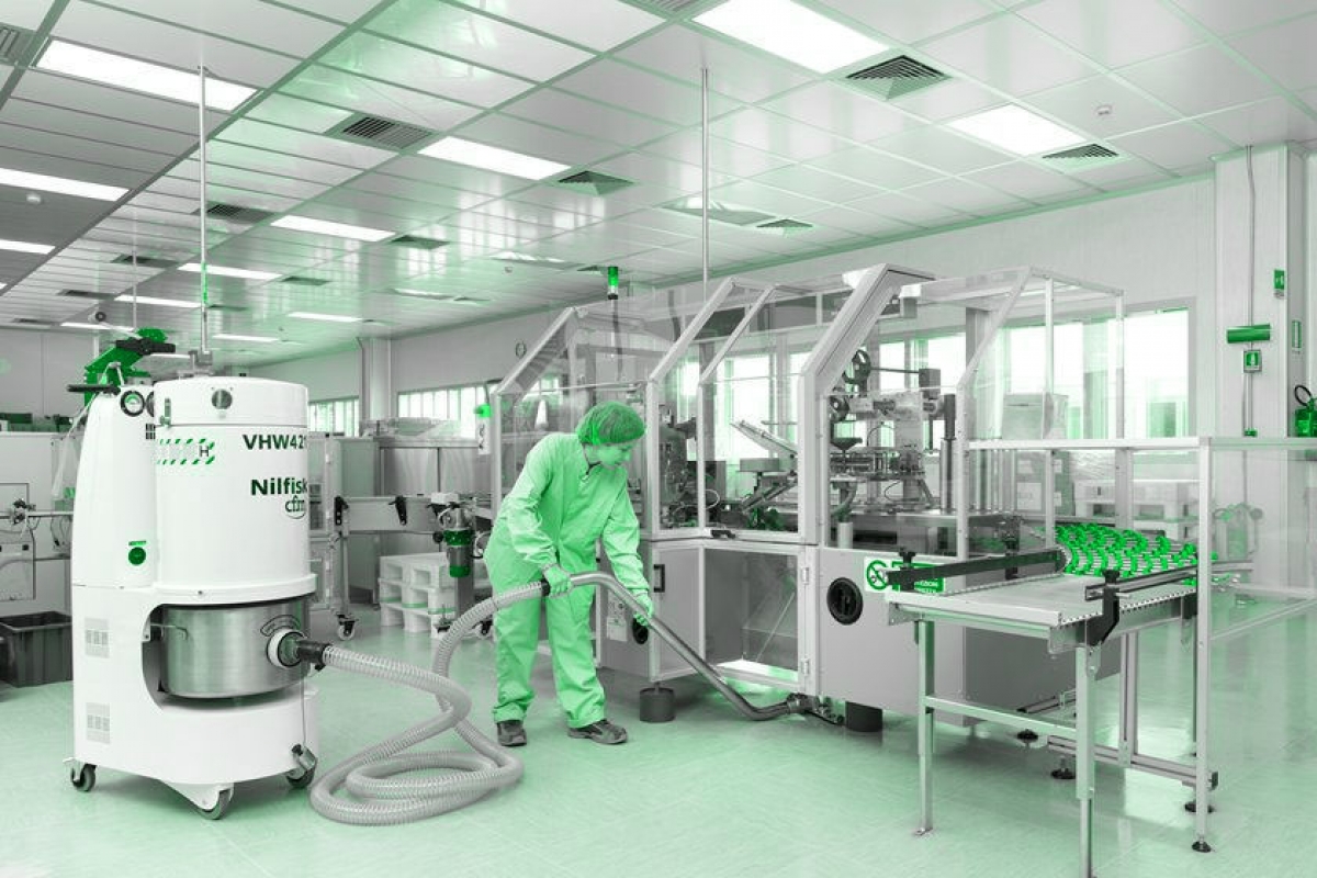
Clean room (area) monitoring items
1. Temperature, relative humidity
1.1 Standard requirements
All levels of clean rooms (areas) should meet the temperature 18℃-28℃, relative humidity within the range of 45%~65%.
1.2 Instruments used
Thermometer and Hygrometer.
1.3 Detection method
1.3.1 Before measuring the indoor air temperature and relative humidity, the purification and air conditioning system should have been running continuously for at least 24 hours. For places with constant temperature requirements, according to the requirements for the temperature and relative humidity fluctuation range, the measurement is carried out continuously for 8h~48h, and the interval between each measurement is not more than 30 min.
1.3.2 According to the temperature and relative humidity fluctuation range, the corresponding instrument with sufficient accuracy should be selected for measurement.
1.4 Indoor measurement points are generally arranged at the following locations
- 1.4.1 At the supply and return air outlets.
- 1.4.2 Representative locations in the constant temperature working area (such as around the process equipment or at equal distances).
- 1.4.3 Room center (for systems without constant temperature requirements, temperature and humidity are only measured at this point).
- 1.4.4 Sensitive element
All measuring points should be at the same height, 0.8m from the ground. They can also be arranged on several planes at different heights from the ground according to the size of the constant temperature zone. The measuring point should be greater than 0.5m from the surface of the outer wall.
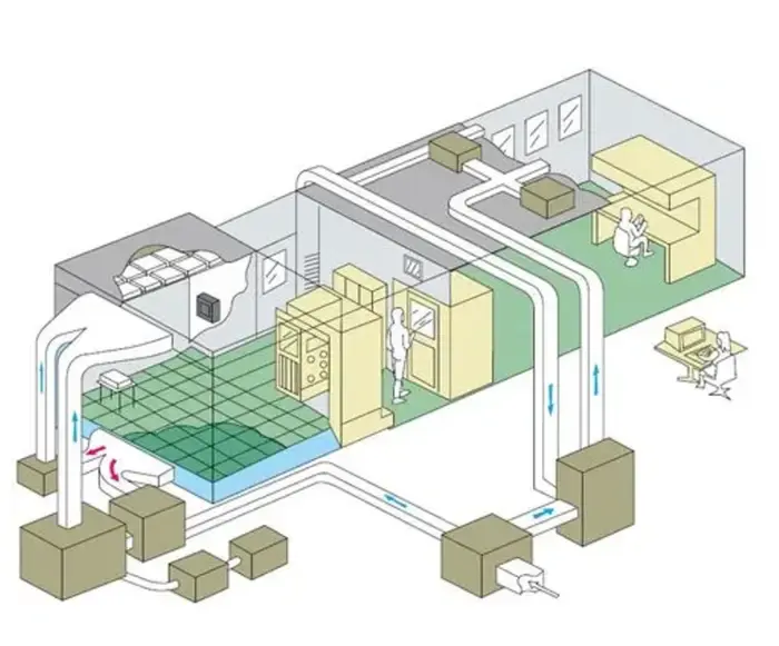
2. Ventilation frequency
2.1 air change rate standard
2.2 Instruments used
Hot ball anemometer, air volume balance tester.
2.3 Detection method
2.3.1 Air volume and wind speed detection must be carried out first, and the effects of purification air conditioning must be obtained under the designed air volume and wind speed conditions.
2.3.2 Before the air volume detection, it is necessary to check whether the fan is running normally, whether the components in the system are installed correctly, whether there are any obstacles (such as whether the filter is blocked or blocked), all valves should be fixed in a certain open position, and the size of the measured air outlet and air duct must be actually measured.
2.3.3 For unidirectional (laminar) clean rooms, the air supply volume is determined by the product of the average wind reading of the room section and the cross-sectional area. The measurement section of the vertical unidirectional (laminar) clean room is a horizontal section 0.8 m from the ground: the horizontal unidirectional (laminar) clean room is a vertical section 0.5 m from the air supply surface. The distance between the measuring points on the section should not be greater than 2 m, and the number of measuring points should be no less than 10, evenly arranged.
2.3.4 For turbulent clean rooms, the air supply volume is determined by the air outlet method or the air duct method.
2.3.5 For air outlets without filters, the method of Appendix 1 of the current national standard "Construction and Acceptance Specifications for Ventilation and Air Conditioning Engineering" GBJ243 can be used.
2.3.6 For air outlets equipped with filters, auxiliary air ducts can be selected according to the form of the air outlet, that is, a straight pipe section with the same cross-section as the air outlet and a length equal to twice the side length of the air outlet can be made of hard plate, connected to the outside of the filter air outlet, and the measuring points are evenly arranged at a minimum of not less than 6 points on the outlet plane of the auxiliary air duct, and the wind speed at each point is measured with a hot ball anemometer. The air volume is determined by multiplying the average wind speed of the air outlet section by the net cross-sectional area of the air outlet.
2.3.7 For air outlets equipped with similar diffusers, the air volume can be found out based on the air volume resistance curve of the diffuser (factory air volume resistance curve or on-site measured air volume resistance curve) and the measured diffuser resistance (the difference between the static pressure inside the orifice plate and the indoor pressure). When measuring, use a micromanometer and a fine Pitot tube, or a thin rubber tube instead of a Pitot tube, but the measuring hole plane must be parallel to the airflow direction. In addition, other methods approved by professional testing departments can also be used.
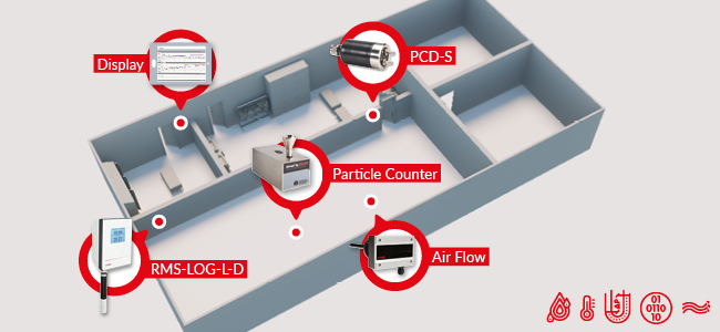
2.4 Result calculation
2.4.1 Average wind speed of the air outlet
V=V1+V2+V3+...+Vn/N
Where:
Average wind speed of the air outlet (m/s);
V1, V2...VN-wind speed of each measuring point (m/s);
N-total number of measuring points (pieces).
2.4.2 Ventilation frequency (times/h)
Ventilation frequency = 3600xFxVxM/SxH
Where:
F-air outlet area (m2);v--measured average wind speed of the air outlet (m/s);
n-total number of wide air outlets (pieces);
S-room area (m2);
H--room height (m)
2.5 Result evaluation: The ventilation frequency should reach the corresponding level of each clean room (area).
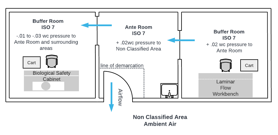
3. Static pressure difference
3.1 Standard requirements: The static pressure difference between adjacent clean rooms of different levels and between clean rooms and non-clean rooms should be greater than 5 Pa; the static pressure difference between clean rooms and outdoor should be greater than 10 Pa.
3.2 Instrument used: digital differential pressure gauge.
3.3 Test method: The static pressure difference should be measured when all doors are closed, and should be measured from the innermost room on the plane to the outside. See Appendix VI of the standard JG)71-9 "Clean Room Construction and Acceptance Specifications". All levels of clean rooms (areas) should comply with the above regulations.
4. Dust number
See GB/T16292-1996 "Test method for suspended particles in clean rooms (areas) in the pharmaceutical industry"
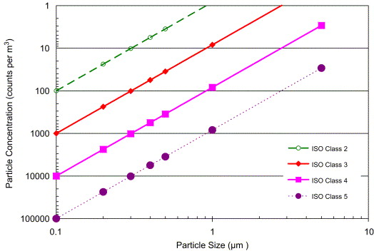
4.1 Standard requirements: The counting concentration method is used, that is, by measuring the number of suspended particles greater than or equal to a certain particle size in a unit volume of air in a clean environment, to assess the cleanliness level of suspended particles in the clean room (area).
Maximum allowable dust count for each cleanliness level
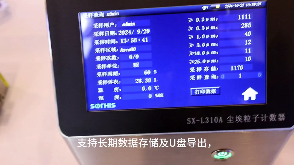
4.2 Instrument used: laser dust particle counter,
4.3 Test rules
4.3.1 Test conditions
- Temperature and relative humidity: The temperature and relative humidity of the clean room (area) should be consistent with its production and process requirements.
- Pressure difference: The pressure difference between clean rooms (areas) with different air cleanliness levels should be 24.9 Pa. Clean rooms (areas) with high air cleanliness level requirements generally require a relative positive pressure to the adjacent clean rooms (areas) with low air cleanliness levels.
4.3.2 Test status: During static testing, there shall be no more than 2 testers in the room, and the test report shall indicate the status adopted during the test.
4.3.3 Test time: For unidirectional flow, the test shall start after the purification air conditioning system has been operating normally for at least 10 rain. For non-unidirectional flow, the test shall start after the purification air conditioning system has been operating normally for at least 30 minutes.
4.3.4 Suspended particle counting
- Number of sampling points and their arrangement
①Minimum number of sampling points
②Location of sampling points: Sampling points are generally evenly arranged on a horizontal plane 0.8 m above the ground; when there are more than 5 sampling points, they can also be arranged in layers in the area 0.8 m to 1.5 m above the ground, but there are no less than 5 points on each layer.
- Limitation of sampling points: For any small clean room or local air purification area, the number of sampling points shall not be less than 2, and the total number of sampling times shall not be less than 5 times. The number of sampling times for each sampling point can be more than 1, and the number of sampling times for different sampling points can be different.
- The minimum sampling volume for each cleanliness level shall be in accordance with the regulations.
- Sampling precautions:
①Sampling can only be carried out after confirming that the air supply volume and pressure difference of the clean room (area) meet the requirements.
②For unidirectional flow, the sampling tube mouth of the counter should face the airflow direction. For non-unidirectional flow, the sampling tube mouth should be upward.
③When arranging the sampling points, the return air outlet should be avoided.
④When sampling, the tester should be on the downwind side of the sampling port.
4.4 Result calculation
4.4.1 Average particle concentration at the sampling point.
A=C1+C2+.. +CN/N
Where: Average particle concentration at a certain sampling point, particles (pieces)/cubic meter;
ci-particle concentration at a certain sampling point (i-1, 2, 3, ...N), particles (pieces)/cubic meter;
N-number of samplings at a certain sampling point, times.
4.4.2 Mean of the average value
M=A1+A2+...+AI/L
Where: M--mean of the average value, i.e., the average particle concentration of the clean room (area), particles/cubic meter:
Ai-average particle concentration of a certain sampling point (i=1, 2, 3.….L), particles/cubic meter:
L-total number of sampling points in a certain clean room (area), pieces.
4.4.3 Standard error
SE=(A1-M) square meters + (A2-M) square meters +... + (AI-M) square meters/L(L-1)
Where: SE-standard error of the mean value, particles/cubic meter.
4.4.4 Upper confidence limit
The upper limit of the estimate calculated by the given confidence level (here 95%) for the actual mean obtained by sampling from the normal distribution will be greater than the actual mean, then the upper limit of the estimated mean calculated is called the upper confidence limit.
UCL=M +txSE
Where: uCL-95% confidence limit of the average value, particles (pieces)/m3.
4.5 Result evaluation
The cleanliness level of floating particles in the county should be determined based on the following two conditions
4.5.1 The average particle concentration of each sampling point must be lower than or equal to the specified level limit, that is, Ai≤level limit.
4.5.2 The 95% confidence limit of the average value of the particle concentration of all sampling points must be lower than or equal to the specified level limit, that is, UCL≤level limit.
5. Detection of indoor sedimentation bacteria
5.1 Standard requirements: Use the sedimentation method, use a 90 mIT nutrient agar culture dish, and settle at the sampling point for 30 minutes, that is, collect the biological particles in the air on the culture dish through the principle of natural sedimentation. After 48 hours, let them multiply to visible colonies at 30℃-35℃ for counting. The number of colonies in the flat culture dish is used to determine the number of live microorganisms in the clean environment, and to assess the cleanliness of the clean room (area).
5.2 Instruments and equipment used: autoclave, biochemical incubator, culture dish, culture medium, balance, clean workbench.
5.3 Test rules
5.3.1 Test status: During static testing, there shall be no more than 2 testers in the room, and the test report shall indicate the state used during the test.
5.3.2 Test time: For unidirectional flow, the test should start after the clean air conditioning system has been operating normally for no less than 10 minutes. For non-unidirectional flow, the test should start after the clean air conditioning system has been operating normally for no less than 30 mils.
5.3.3 Minimum number of sampling points: Minimum number of sampling points for sedimentation method.
5.3.4 Arrangement of sampling points: The location of the sampling points can be the same as the suspended particle test points. The location of the sampling points in the working area is about 0.8m~1.5m from the ground. Sampling points can be added at key equipment or key work activity ranges.
5.4 Result calculation
Use the counting method to obtain the number of colonies in each culture dish and calculate the average number of colonies.
5.5 Result evaluation
Use the average number of colonies to judge the microorganisms in the air of the clean room (area). The average number of colonies in the clean room (area) must be lower than the selected evaluation standard. If the average number of colonies in a clean room (area) exceeds the evaluation standard, the area must be disinfected first, and then resampled twice, and the test results must be qualified. During the environmental monitoring process, we found that there were many problems in the self-test of ventilation frequency in enterprises. Most enterprises did not make auxiliary air ducts according to the requirements of standard methods. Although some enterprises made auxiliary air ducts and fixed anemometers in them, the position of the anemometer probe was incorrect. The probe should be perpendicular to the airflow direction. In the dust number detection, it should be noted that not only the 95% confidence limit of the average value of the particle concentration of all sampling points must be ≤ the specified level limit, but also the average particle concentration of each sampling point must be ≤ the specified level limit. In the sedimentation bacteria detection, it should be noted that while meeting the minimum number of measurement points, the minimum number of culture dishes should also be met.
 +86 18186671616
 Jason@cleanroomequips.com
 MENU
MENU


