+86 13638632902
 Jason@cleanroomequips.com


 MENU
MENU
A cleanroom is an engineered environment that contains architectural, HVAC and operational elements. Each industry has its own definition of ‘compliance’ and so meeting an ISO classification is only the first step for a cleanroom facility. For example, molecular contamination control for semiconductor manufacturing has very different requirements to the microbial contamination control needed for pharmaceutical products.
Drawing on Deiiang™ project records, we approach every design individually based on real-world engineering constraints. Our track record includes:
Global Experience: 300+ projects across 15 countries.
Scale & Precision: 1,500,000+ m² delivered, from iso 8 to ISO 1.
Reliability: 98.6% first-time testing pass rate.
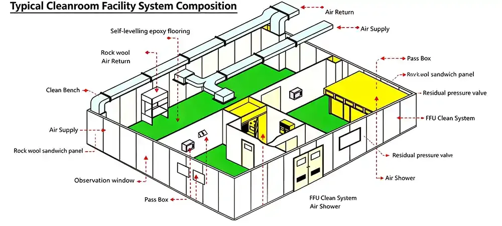
Typical cleanroom facility system composition — the architectural envelope works together with HVAC, filtration, personnel and material flows, monitoring, and control systems.
What Are Cleanroom Facilities?
A cleanroom facility is more than just a clean production room. A cleanroom facility is the sum of all areas that form a controlled environment to support production. These areas comprise gowning rooms as well as mechanical spaces. The terms “cleanroom”, “cleanroom facility” and “controlled environment” define a scope of design and scope of regulations that are relevant to each of these terms.
Clean production areas and critical process zones. These are areas where high levels of contamination could affect product during production and therefore the highest cleanliness standards apply.
Gowning, air shower, and personnel purification areas – spaces that allow for the cleaning of personnel entering and leaving a cleanroom area, typically one level below the cleanroom itself.
Material transfer, washing, and staging rooms - These areas are set up to control the transfer of materials between non-clean and clean areas and are typically equipped with interlocked doors or pass boxes to this end.
HVAC, HEPA/ULPA filtration, and exhaust systems – Environmental Control Systems which regulate air cleanliness, temperature, humidity, and pressure.
Utilities, monitoring, alarms and control systems. Here sensors and interlocks continuously check the production processes and give a signal if any parameter goes out of specified limits.
In discussions around cleanrooms, the term ‘cleanroom’ is often used to describe the classified room itself. The term ‘cleanroom facility’ however describes the sum of all support areas (airlocks, mechanical rooms, waste corridors, etc. including the emergency egress routes). A ‘controlled environment’ describes a broader term and can be used to describe areas that are not classified but do have some environmental control, i.e. a temperature controlled warehouse. Each area must be designed with the appropriate levels of cleanliness, access and monitoring.
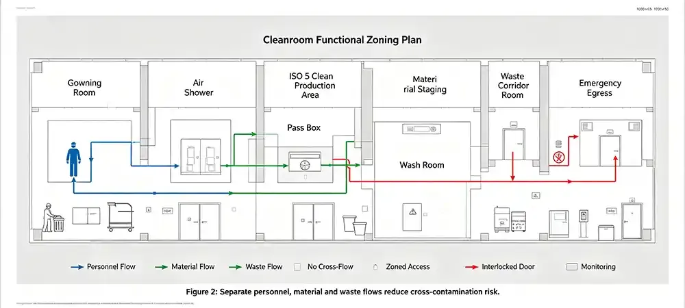
Example of cleanroom facility zoning and flow separation
Start With the User Requirement Specification
A professional design process starts by determining the requirements of the process and the risks involved. Deciding on wall panels or air handling units is not part of the design process. A detailed User Requirement Specification (URS) is the basis for all subsequent design decisions. Without a clear URS, the design team will often over specify/under specify the required facility, leading to high energy consumption and/or non-compliance.
- Product, process steps, and main sources of contamination.
- Target ISO cleanliness class or gmp background (e.g., iso 5, EU GMP Grade B).
- Required at-rest and operational states.
- Temperature, humidity, and pressure differential ranges.
- Equipment heat load, exhaust volume, and utility requirements.
While cleanliness class is one of the inputs to the final design, others such as product exposure, number of personnel, equipment particle generation, door opening, cleaning methods, and maintenance access also impact the design. For example, a semiconductor photolithography area would require strict molecular contamination control and good vibration isolation. In contrast, a food packaging cleanroom would require washdown compatibility and moisture resistance. A well-defined URS will prevent you from designing a facility from the wall panels backward.
Deiiang™ anonymized project requirement summary:
Clean area: 1,250 m² | Rooms: 14 | Design personnel: 18 per shift | Critical equipment heat load: 62 kW | Design temperature: 21 ± 2°C | Design humidity: 45 ± 5% RH | Planned operation: 8,000 hours/year
Clean area: 1,250 m² | Rooms: 14 | Design personnel: 18 per shift | Critical equipment heat load: 62 kW | Design temperature: 21 ± 2°C | Design humidity: 45 ± 5% RH | Planned operation: 8,000 hours/year

Cleanroom facility design and delivery workflow.
Cleanroom Classification and Applicable Standards
ISO 14644 Cleanroom Classification
The ISO 14644 series is probably the most used framework to classify, to check and to test air cleanness. The single parts of this framework must be indicated by their corresponding reference number and where appropriate also by the edition of the corresponding standard. When designing a facility the following parts of the ISO 14644 series are relevant.
- ISO 14644-1:2015 – Classification of air cleanliness by particle concentration.
- ISO 14644-2:2015 – Monitoring to provide evidence of cleanroom performance related to air cleanliness.
- iso 14644-3:2019 – Test methods.
- iso 14644-4:2022 – Design, construction and start-up.
- iso 14644-5:2004 – Operations.
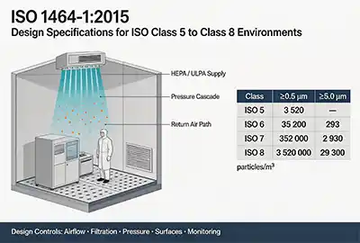
Designers must check the specific particle size and the required concentration for the process under design. In order to compare values for different classes, the values given for ISO classification refer to a particle size of ≥0.5 μm. iso class 5 ≥0.5 μm has 3,520 particles/m³. iso class 7 ≥0.5 μm has 352,000 particles/m³ under the same sampling conditions. Values must be checked against the test method in question and do not imply that the room will maintain that classification during actual use. The values do form the basis of the classification of a room.
GMP and Industry-Specific Requirements
Airborne particle concentration is the basis for ISO classification, but for pharmaceutical applications other factors must also be controlled, e.g. microbial contamination, process state, personnel, cleaning and disinfection, documentation.
In accordance with GMP (Good Manufacturing Practice) guidelines, i.e. EU GMP Annex 1, cleanrooms are classified into the grades A, B, C, D, which contain limits for non-viable as well as viable particles. Note, however, that these grades are not equivalent to the ISO cleanroom classes, since in addition to particle limits, Annex 1 also contains limits for microorganisms. Furthermore, a process simulation, e.g. via media fills, is required for the cleanroom grades A, B, C, D.
Pharmaceutical and biotech facilities: Control viable/non-viable particles with environmental monitoring and cleaning validation.
Medical device cleanrooms: need to operate under ISO 14644 requirements for cleaning and particle control, but additional means to control bioburden will also be required and Process Validation means will be needed.
Semiconductor and electronics facilities: Control AMC, ESD, vibration, and electromagnetic interference.
Laboratories and controlled environments: Bio safety measures, negative pressure and specialized exhaust treatment.
Important: ISO Class 5 does not automatically mean that a facility is GMP-compliant. Compliance depends on the applicable process, jurisdiction, operational controls, and validation evidence.
| Standard / Framework | Primary Purpose | Typical Application | What to Confirm at Design Stage |
|---|---|---|---|
| ISO 14644 | Cleanliness classification, testing, monitoring | Multi-industry | Class, occupancy state, test methods |
| EU GMP | Pharmaceutical quality management | Pharmaceutical, sterile manufacturing | Zoning, operational controls, contamination control strategy |
| FDA/cGMP | US regulated production | Pharmaceutical, medical devices | Product and process-specific requirements |
| Industry internal specifications | Control of specific process risks | Semiconductor, electronics | Molecular contamination, ESD, vibration |
| Standard | Purpose & Application |
|---|---|
| ISO 14644 | Cleanliness classification, testing, monitoring — multi-industry |
| EU GMP | Pharmaceutical quality management — sterile manufacturing |
| FDA/cGMP | US regulated production — pharma & devices |
| Industry specs | Process risk control — semiconductor, electronics |
Cleanrooms classified according to ISO 14644-1 (Class 5 in this case) do not automatically meet EU GMP requirements for Grade A areas, since in addition to microbial validation, other operational requirements have to be fulfilled.
Core Elements of Cleanroom Facility Design
Layout and Contamination Zoning
In designing a process layout, separate areas for clean products, a buffer area and non-clean products are required. In designing the flows of personnel, materials and waste through a facility, all flows should go in one direction only. All cross flows should be avoided. Every cross flow allows for the potential of operators and carts to transfer particles from dirty to clean areas, totally defeating all contamination control efforts.
Airlocks and pass-throughs would be incorporated into the design of a zoned facility in order to ensure that pressure cascades are maintained. Typical designs for a GMP facility would incorporate a material airlock between the corridor and the cleanroom and a personnel airlock complete with gowning areas for personnel transfer between the corridor and the cleanroom. The design of the personnel airlock would allow for only one door to be opened at a time in order to prevent contaminated air entering the clean area when two doors are opened simultaneously.
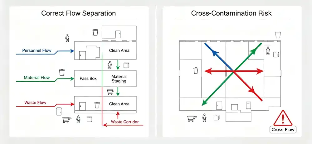
Correct flow separation (left) vs. cross-contamination risk (right).
Cleanroom HVAC and Airflow Design
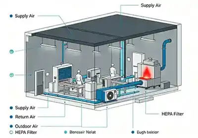
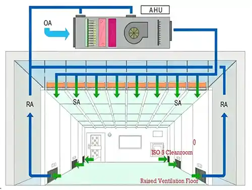
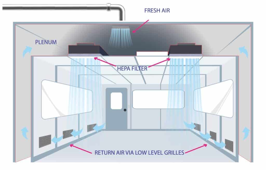
Supply air, return air, thermal load, moisture load, personnel load, and process exhaust must all be designed as one system. Air change rate cannot be determined independently of Room Volume, Containment Sources and Recovery Time required. A design specified at 30 ACH for example in a small room may be totally inadequate due to high equipment particle emission, whereas 15 ACH may be acceptable in large well controlled spaces.
Deiiang™ Project Data – Semiconductor Assembly Cleanroom (ISO 7) The design air volume for the Deiiang™ project was set at 28,000m3/h. The unit area airflow was therefore set at 95m3/h·m2. Measured average air velocity leaving the HEPA supply diffusers was 0.42m/s. Particle recovery time after challenge with aerosol was 6.5 minutes. Airflow balancing tolerance at supply diffusers was ±5%. Following the optimization, fan energy consumption was reduced from 18.4kW to 15.1kW. Note: These figures are project specific and should not be used as design rules.
Laminar (unidirectional) airflow is characterized in terms of its direction, whereas turbulent (non-unidirectional) airflow does not follow a single path and relies on dilution for controlling levels of particulate matter in cleanrooms. Therefore, laminar airflow is suited to cleanrooms of iso 5 classification and above, whereas turbulent flow is generally suited to cleanrooms of lower classification (down to ISO 6).
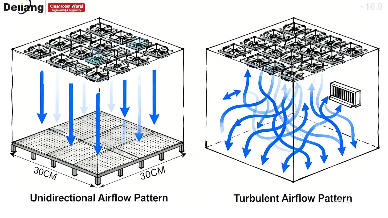
Airflow principle comparison and CFD visualization.
HEPA and ULPA Filtration
The efficiency of a filter, the location where it is installed, the pressure drop that it causes, leak testing and the replacement conditions are all interrelated. So a HEPA filter for example does not just remove 99.97% of particles, the value of 99.97% only applies to the most penetrating particle size (MPPS) and under test conditions. The actual in-situ efficiency of a filter depends on the filter grade, the media, the frame seal and the airflow uniformity.
The prefilter extends the HEPA filter life by capturing large amounts of particles in the air. In areas of high clean lines, terminal HEPA filters are installed in the ceiling to prevent contamination of the duct work downstream. Deiiang’s FFU and HEPA filter modules are EN1822 tested with Efficiency Classes H13 and H14 available.
The initial resistance to airflow is dependent on the media area and is 150-220 Pa at rated airflow. The filter frames are made from aluminum, stainless steel or galvanized steel and are sealed with gel-seal or gasket. Every filter is factory scan-tested with a photometer before it is shipped out.
Deiiang™ product data module:
FFU Model FFU-470 DC, Airflow 1200 m3/h, Static Pressure 160 Pa. H13 filtered frames made of aluminum with gel-seal frame held to strict factory test standards including scan test with a photometer. Refer to current FFU Technical Data Sheet for final and detailed specifications.
FFU Model FFU-470 DC, Airflow 1200 m3/h, Static Pressure 160 Pa. H13 filtered frames made of aluminum with gel-seal frame held to strict factory test standards including scan test with a photometer. Refer to current FFU Technical Data Sheet for final and detailed specifications.
Pressure Cascade and Room Tightness
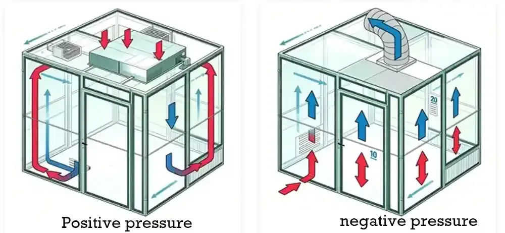
Positive and negative pressure differentials serve different purposes. Product protection typically uses positive pressure in clean zones relative to adjacent less-clean areas, so airflow moves from clean to less clean. Hazardous or toxic processes may require negative pressure to prevent contaminants from escaping. The absolute pressure value is less important than the consistent direction of airflow through doorways and pass-throughs.
Objects such as door openings, pass boxes, and exhaust grilles can upset the pressure balance. Therefore, pressure alarms and interlocks are required to alert personnel of any door left open, or failure of an exhaust fan. The Deiiang™ pharmaceutical project monitored the pressure differential between the clean corridor and the adjacent preparation area on a continuous basis. Under normal conditions the differential pressure was maintained at 15 ± 2 Pa. Upon a door opening event, the pressure would recover to the set point within less than 20 seconds.
Example of pressure differential trend in a cleanroom suite (client sensitive information removed).
Walls, Ceilings, Floors and Doors
A cleanroom building envelope must be airtight, smooth, cleanable, impact resistant and low shedding. It is at the joints and penetrations that failure is most likely to occur. A wall panel that looks OK in a brochure can leak at the floor track or ceiling junction if it is not installed with correct sealing to these interfaces.
Deiiang™ cleanroom wall panels are available in various thicknesses from 50 mm up to and including 100 mm, with cores made of rock wool, glass magnesium, aluminum honeycomb or PU foam. The surfaces can be supplied with an anti-static powder coating, a PET color-coated steel, or a stainless steel finish.
Cleanroom wall panels have been tested for fire resistance, and certain versions have even been approved for 120 minutes. The tongue-and-groove joint is designed to prevent air leakage while at the same time providing a smooth surface that is easy to clean. The operating range for temperature is verified for -40°C up to +80°C, and for relative humidity up to 95% RH, depending on the core and surface finish that is chosen.
Temperature, Humidity, ESD and Process Utilities
Temperature and humidity targets must fulfill process requirements, personnel comfort and material properties. Whereas in the area of electronics and semiconductors highest requirements regarding exact humidity control to avoid electrostatic discharge (ESD) and moisture-related defects are stipulated, in the area of biopharmaceuticals highest requirements regarding microbial growth control and cleaning compatibility are stipulated. All process utilities (e.g. compressed air, nitrogen, vacuum) must be integrated into the cleanroom design in order to avoid particle generation and contamination.
Local Climate and Regional Design Factors
Designing a cleanroom facility is not a copy-paste exercise. Climate plays a large part in the design of the HVAC load, the materials that can be specified and the long term operating costs. In designing a cleanroom facility the designer must adapt to the local psychrometric conditions. For example, a cleanroom designed in Singapore would require a lot more dehumidification than the same design in Denver even if both were designed to the same setpoints for temperature and humidity.
Hot and Humid Regions
In hot, humid climates, a large portion of the outside air consists of latent heat which must be removed by the cooling coil and, in addition, the air must be dehumidified, a process which usually requires reheating of the cooled air. There is an increased risk of condensation on exterior surfaces of buildings and supply diffusers which will require special attention in the form of insulation and vapor barriers. Because of the large amount of moisture in the air introduced through door openings, there will be occurrences of large humidity excursions. In coastal areas, there is also a corrosion problem with the structural steel and HVAC equipment.
Cold Regions
In winter time preheating and humidifying of incoming fresh air is necessary. Special attention has to be paid to exterior walls and roofs in order to avoid thermal bridges which cause condensation and mold growth. Low outside humidity leads to high static electricity risk inside the building, which can be counteracted by humidification and by means of a grounded floor. Exhaust air heat recovery might be economically justifiable.
High Altitude or Dusty Regions
Outside air density decreases with altitude, so fan and heat exchanger performance must be calculated using local outdoor air conditions. Sandy or very dusty locations have high outdoor particulate load. Therefore the prefilter will require frequent changeout and use of very robust intake screens.
For instance, for summer design dry-bulb temperature of 38°C and wet-bulb temperature of 28°C, the cooling coil has to deal with a large enthalpy difference, therefore the chiller selection needs to be changed for optimal performance.
Deiiang™ engineering team analyzed the annual average relative humidity of 73% and design summer conditions of 35°C DB/ 29°C WB for a project in Bangkok, Thailand based on the historical weather data from local meteorological department for the year of 2022. Deiiang™ engineering team analyzes the annual outdoor air temperature and humidity profile against the cleanroom setpoint in order to fine-tune the energy recovery and dehumidification in the engineering design.
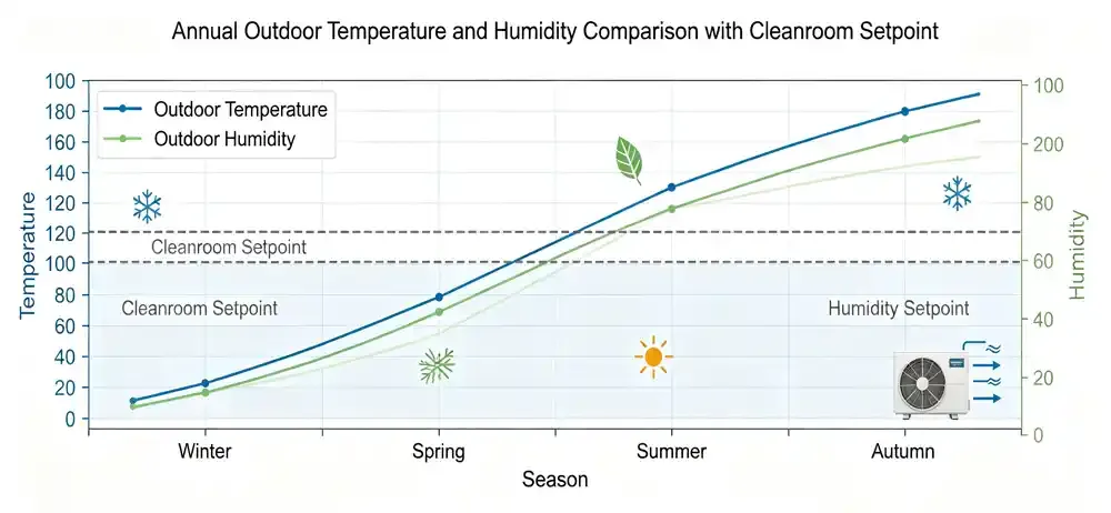
Seasonal outdoor conditions vs. cleanroom setpoint.
From Design to Qualification and Certification
Proof of compliance with legislation does not automatically occur upon completion of construction of a facility. Design and construction information, together with associated records, commissioning and test data, and ongoing monitoring information, collectively demonstrate compliance with legislation throughout the four phases of a facility’s life cycle.
- Design review and risk assessment – verify that the URS is met and potential failure modes are identified.
- Installation and commissioning – confirm that components are installed correctly and function as intended.
- Performance testing and qualification – measure particle counts, HEPA integrity, airflow, pressure differentials, recovery time, temperature, and humidity.
- Routine monitoring and requalification – periodic testing to ensure the facility remains in control.
Facilities can be classified, validated or third-party tested for parameters like airborne particle concentrations, HEPA filter integrity by means of scan tests or photometer tests, air volume and air velocity, room pressure differences, recovery times, temperatures and humidities as well as airflow visualization by means of smoke studies. Instead of stating ISO certification in misleading promises, an accurate statement would be based on the test methods which were applied.
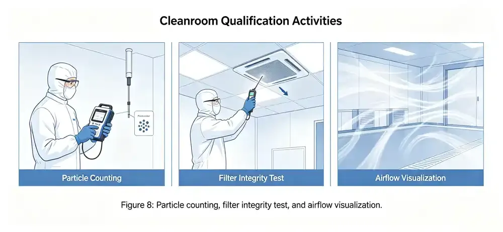
Cleanroom qualification activities — particle counting, filter integrity test, and airflow visualization.
Deiiang Project Evidence
Real project evidence is the strongest proof of capability. The following anonymized example illustrates how design choices translate into measured results.
High-Humidity Pharmaceutical Packaging Cleanroom
Project overview: Secondary packaging area for Pharmaceuticals in a coastal tropical location. The area is designed as an ISO 7 total clean area of 850 m² comprising packaging halls, material airlocks and gowning rooms.
Design challenge: In the outside area of the building the humidity was mostly above 80% RH. The process required a humidity of 50 ± 5% RH at 22 ± 2°C. The building height was limited. Production was not allowed to come to a standstill for more than 72 hours during the installation period.
Deiiang solution: Prefabricated modular wall panels containing a 50 mm rock wool core were specified and constructed from anti-corrosion coated steel to aid installation. A dedicated fresh air pre-conditioning unit has been specified to enable deep cooling and reheat to maintain humidity. The Pressure Cascade has been designed as packaging hall > corridor > non-clean storage area. The Ceiling Grid has been installed with pre-wired FFU modules to minimize on-site installation work.
Measured results:
Particle counts at rest equal to 15% of ISO 7 counts, pressure differential held constant at 12 ± 2 Pa, door open/recovery time equal to 4.8 minutes, and temperature fluctuation equal to ±0.9°C. HVAC power reduced by 18% after balancing and control optimization compared to constant volume design. Total on-site time equal to 21 days including commissioning.
Supplemental photos, floor plans, and test reports for the above project can be released under NDA and will be clearly marked with location, project type, and stage.
Common Cleanroom Facility Design Mistakes
MYTH 1
“Higher air change rates always mean a cleaner room.”
Increasing airflow does not necessarily solve contamination problems and can lead to a host of other problems such as turbulence, noise, excess energy usage and pressure imbalance. The air change rate for a given room is primarily a function of the cleanliness class, contamination load, room geometry and recovery time.
Action: Validation of the design by means of risk assessment, airflow visualization and on-site recovery testing as opposed to designation of a single universal air change rate.
MYTH 2
“Installing HEPA filters creates a compliant cleanroom.”
The test failing is not only because of the filters. There can be leaks, joints, return air dead zones, door openings, personnel behavior and cleaning procedures causing the test to fail.
Action: Verify filter integrity, room tightness, airflow pattern, and operational procedures together.
MYTH 3
“ISO class can be directly equated to GMP grade.”
In summary, two different systems are in place. Their objectives and scope of assessment are different. ISO classification does not supersede the relevant pharmaceutical requirements regarding microorganisms, process status, personnel and documentation.
Action: Confirm the industry, product, jurisdiction, and process first, then build a matrix of applicable standards.
MYTH 4
“Once a cleanroom passes acceptance, it remains compliant indefinitely.”
Filter loading, equipment changes, personnel count, and maintenance activities all alter room performance over time.
Action: Establish a monitoring, alarm, maintenance, and periodic requalification plan.
MYTH 5
“All industries can use the same materials and layout.”
Different types of contamination risks are associated with Pharmaceutical, Semiconductor and Medical Device projects. Different requirements for disinfectant compatibility, ESD, molecular contamination and exhaust isolation exist.
Cleanroom Facility Design Checklist
The following core checklist provides a quick decision framework for planning a cleanroom facility. Each item should be documented and reviewed.
Define process and compliance requirements.
Establish contamination zones and flows.
Calculate HVAC and filtration requirements.
Select cleanable, compatible materials.
Test, document, and continuously monitor performance.
This checklist is intentionally concise. Detailed sub-items should be developed based on the URS and risk assessment.
How to Select a Cleanroom Facility Partner
When evaluating a cleanroom facility partner, review the following evidence:
- Proven project experience in your industry and cleanliness class.
- Performance parameters backed by test standards and reports.
- Capability to integrate design, manufacturing, installation, and commissioning.
- Ability to deliver complete as-built and testing documentation.
- Local after-sales or remote technical support capability.
Deiiang™ provides Cleanroom Design Review, URS Preliminary Assessment and Project Reference Documents etc. upon request. Deiiang™’s Product Designer Jason.peng and Engineering Team members can provide detailed Technical Specifications as well as on-site support. As a company with over 300 completed projects and a first-time pass rate of 98.6% (pharmaceutical, semiconductor and medical device projects), each new project is conducted with totally new and fresh engineering analysis instead of relying on templates.
Request a cleanroom design review | Submit your URS for a preliminary assessment | Download the cleanroom facility planning checklist | Ask for relevant Deiiang project references
Frequently Asked Questions
What is included in a cleanroom facility?
In addition to controlled clean production spaces a cleanroom facility also contains supporting areas such as a gowning room, airlocks, material transfer hatches, mechanical rooms, monitoring systems etc. The entire facility has to be designed to maintain contamination control.
Which standards apply to cleanroom facility design?
The primary international standard for air cleanliness classification and testing is ISO 14644 series. However, additional standards such as EU GMP, FDA cGMP or even internal specifications might apply to a particular product or market.
What is the difference between ISO cleanroom classes and GMP grades?
As ISO classes for clean rooms define limits for the concentration of particles of certain size, GMP grades add requirements for microbial counts, operational modes and process steps. Clean rooms of ISO classes may not necessarily fulfill GMP requirements, e.g. due to higher microbial counts or lack of documentation.
How is the required cleanroom class determined?
This Class is based on Process Risk Assessment, Product Sensitivity and Regulatory Requirements. It is started from URS and considers items like Exposure, Personnel, Equipment and Cleaning Methods.
How much does a cleanroom facility cost?
The cost can vary widely based on a number of factors such as area, cleanliness class, temperature and humidity control, exhaust volume, utilities, wall and ceiling materials, local labor and validation scope. A rough budget for a project can only be developed after reviewing the URS for the project and the site in question.
How long does cleanroom design and construction take?
Design can typically take 2–4 weeks, manufacturing 4–12 weeks, installation 2–8 weeks and testing/commissioning 1–4 weeks, depending on the complexity and scope of the Modular Cleanroom required. In comparison to conventional construction, Modular Cleanrooms can be delivered much faster.
How often should a cleanroom be tested?
Particle counts and pressure differences should be recorded on a continuous basis or at fixed time intervals. Integrity tests of HEPA filters, measurement of airflow and recovery tests are typically conducted during the initial qualification. For non-critical applications these tests are then conducted on a semi-annual or annual basis, while for critical applications more frequent tests are conducted.
Can an existing facility be upgraded to a higher cleanliness class?
Depends on existing HVAC capacity, room air-tightness and room layout. Filter changes, more air changes per hour, optimum pressure cascade, additional air-locks or even a new surface to the walls and floor may be required. First a feasibility study has to be done.
Micro-Glossary
ISO Classification: Clean rooms are classified based on clean air which contains a controlled amount of airborne particles by size according to ISO 14644-1.
HEPA Filter: High Efficiency Particulate Air Filter for air to contain very little particles, they can be of a certain quality. This Filter is tested against test standards, EN1822 for HEPA filters for example.
Pressure Cascade: The pressure difference between adjacent rooms traveling in a predetermined direction.
Airflow Visualization: The test method for airflow visualization by means of visible test media (e.g. smoke, fog) to check the airflow, turbulence, return flow and areas of stagnation.
Recovery Time: The time it takes for a cleanroom to return to its specified cleanliness level after a particle disturbance has occurred.
References
- ISO 14644-1:2015 — Cleanrooms and associated controlled environments — Part 1: Classification of air cleanliness by particle concentration. ISO Website
- ISO 14644-2:2015 — Monitoring to provide evidence of cleanroom performance related to air cleanliness by particle concentration. ISO Website
- iso 14644-3:2019 — Test methods. ISO Website
- ISO 14644-4:2022 — Design, construction and start-up. ISO Website
- EU GMP Annex 1 — Manufacture of Sterile Medicinal Products. European Commission
- U.S. FDA — Current Good Manufacturing Practice (cGMP) regulations. FDA Website
- EN 1822 — High efficiency air filters (EPA, HEPA and ULPA). CEN Standards
Prepared by Deiiang™ Cleanroom Design Team · Product Designer: Jason.peng · For more technical information, please contact our engineering support.