+86 13638632902
 Jason@cleanroomequips.com


 MENU
MENU
This article traces the evolution of fume hood technology across four eras: open bench, enclosed CAV cabinet, VAV cabinet, and sensor-controlled platforms.
Every innovation addresses one core question: how much exhaust air ensures full operator safety across all working conditions.
Readers will explore the full history of Fume Hoods, from 19th-century chimneys to modern VAV retrofit solutions.
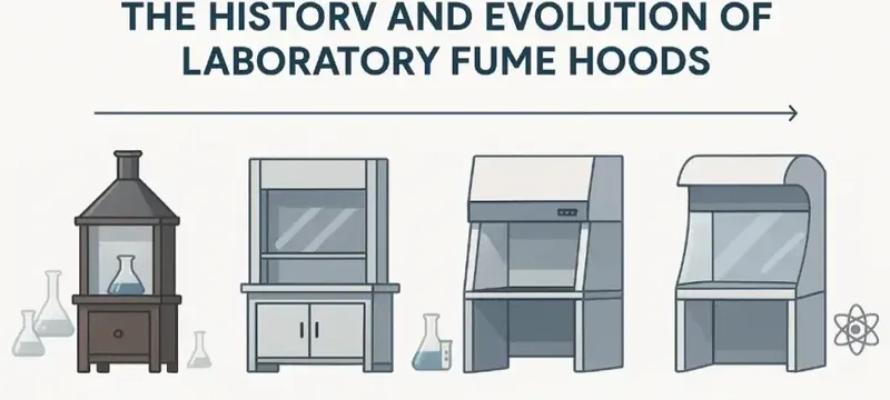
19th-Century Origins: From Open Benches to First Enclosed Hoods
The Laboratory Fume Hood origins trace back to industrial organic chemistry, not electronics. Early labs used tall chimney flues and natural thermal draft alone.
By the early 1820s, open bench setups were standard. No face velocity measurements existed, so exposure risk depended on chimney height and weather.
Early fume hood design for enclosed cabinets was developed in German universities, driven by toxic coal-tar dye experiments.
- 1820s–1870s: Open bench systems with natural draft only
- 1880s: First enclosed hood with sliding sash and powered exhaust fan
- 1890s–1910s: Wood-and-glass cabinets adopted by university chemists
- 1920s: Commercial production begins, with metal replacing wooden bodies
The definitive answer to when were fume hoods invented is the 1880s, as commercial production followed later. This decade marks a key milestone in fume hood historical development.
Open Bench Extraction (1820s–1870s)
The development of early fume hood design can be traced back to open benches under chimneys, with fire driving exhaust flow.
Without a sash or fan, no defined containment zone existed. Cross-drafts could easily carry vapours into a worker’s breathing zone.
This first phase of fume hood historical development offered very low safety margins, with ventilation rates based on custom not data.
Deiiang lead designer Jason Peng notes informal open-bench setups still exist in small workshops, carrying 3–5x higher exposure risk.
The First Enclosed Fume Hood Designs (1880s–1910s)
The next major advance came in the 1880s, with a wooden cabinet and exhaust fan that laid groundwork for modern fume hood technology.
The sash defined vapour containment boundaries, and the fan reduced reliance on external wind conditions.
This 1880s design established the core architecture that remains the basis of all modern fume hood technology today.
Later chapters of the history of fume hood design build on this core sash-and-powered-exhaust framework.
Mid-20th Century: Standardization and CAV System Dominance
The rise of laboratory safety drove a shift from artisanal practices to formal standards, a key phase in fume hood historical development.
This period transformed ventilation engineering, shifting focus from function to verification, and advancing the evolution of fume hood performance standards.
This era also introduced the written history of fume hood standards, alongside widespread adoption of the CAV system as default.
By the 1960s, decades after the era when were fume hoods invented, formal performance standards had fully matured.
Table 1: CAV versus VAV hood behaviour
| Parameter | CAV hood | VAV hood |
|---|---|---|
| Airflow through hood | Constant, 24 hours | Changes with sash position |
| Face velocity control | Passive, sash-dependent | Active, sensor-driven |
| Sash-down energy use | Full design flow | 30–40% of design flow |
| Room pressure stability | Poor under load change | Within ±5 Pa |
| System hardware | Damper and balancing plate only | Sensors, controller, actuator |
| Initial installation cost | Low (damper and balancing plate only) | Moderate (sensors, controller, actuator) |
| Retrofit complexity | Baseline | Intermediate, ducts evaluated |
| Parameter | CAV hood | VAV hood |
|---|---|---|
| Airflow through hood | Constant, 24 hours | Changes with sash position |
| Face velocity control | Passive, sash-dependent | Active, sensor-driven |
| Sash-down energy use | Full design flow | 30–40% of design flow |
| Room pressure stability | Poor under load change | Within ±5 Pa |
| System hardware | Damper and balancing plate only | Sensors, controller, actuator |
| Initial installation cost | Low (damper and balancing plate only) | Moderate (sensors, controller, actuator) |
| Retrofit complexity | Baseline | Intermediate, ducts evaluated |
Safety Reforms and Early Standard Setting (1920s–1960s)
OSHA 29 CFR 1910.1450 regulations trace their roots to this era, building on laboratory fume hood origins in chemistry research [5].
World War II chemical weapons and industrial research accelerated demand for consistent containment, laying regulatory groundwork.
SEFA 1 became the first dedicated standard for laboratory fume hoods [3], setting the 80–120 fpm face velocity target still used today.
Wood cabinets were replaced with metal, with phenolic or epoxy work surfaces. This era also saw fume hood safety evolution produce codes like NFPA 45 [6].
A Chemical Fume Hood timeline places 1920s production, 1940s metal build and 1960s standardization in one 50-year window.
Laboratory fume hood origins in chemistry directly shaped these rules, as early monitored emissions were solvent vapours and fumes.
Constant Air Volume (CAV) Operating Principles
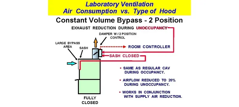
CAV hoods maintain a fixed exhaust volume, such as 0.35 m³/s for an entire cabinet. Face velocity depends solely on sash opening size.
At 1 m² opening, 0.35 m³/s delivers 0.35 m/s, below the 0.5 m/s target. At 0.5 m², it reACHes 0.7 m/s, wasting significant energy.
Its simple construction made CAV the dominant system for two decades, a staple of mid-century fume hood historical development.
Deiiang field teams find 60% of underperforming CAV hoods fail due to misadjusted balancing plates, not insufficient fan capacity.
The Evolution to VAV: Energy Efficiency and Precision Control
The evolution of fume hood technology from fixed to variable volume is one of the most important advances in lab ventilation efficiency.
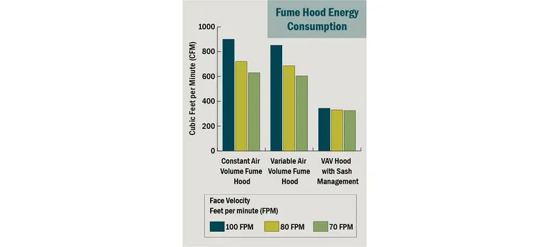
The 1973 oil crisis upended lab ventilation economics. A building with 20 CAV hoods could use more energy per m² than a typical office tower.
VAV fume hood history begins here, as sensors and controls enable variable airflow while maintaining consistent face velocity.
Table 2: Reported VAV retrofit performance indicators
| Indicator | CAV baseline | VAV result | Change |
|---|---|---|---|
| Sash-down exhaust volume | 100% | 30–40% | 60–70% turndown |
| Annual fan and thermal energy | 100% | 50–70% | 30–50% saving |
| Face velocity deviation | ±20% | ±5% | Tighter control |
| Room pressure stability | ±15 Pa | ±5 Pa | Improved |
| Indicator | CAV baseline | VAV result |
|---|---|---|
| Sash-down exhaust volume | 100% | 30–40% |
| Annual fan and thermal energy | 100% | 50–70% |
| Face velocity deviation | ±20% | ±5% |
| Room pressure stability | ±15 Pa | ±5 Pa |
Performance values are drawn from Deiiang catalogue specifications and project-reported retrofit outcomes.
CAV Limitations That Spurred VAV Development
CAV hoods cannot detect sash position, causing constant over-ventilation. This inefficiency is a key driver of VAV fume hood history and adoption.
A 0.35 m³/s hood moves roughly 11 million m³ of conditioned air yearly, translating to very high operational energy costs.
CAV systems also disrupt room pressure control, as each hood adds a fixed load. Adding one hood unbalances the entire distribution.
VAV systems launched around 1980 faced high PLC costs and sensor drift, slowing widespread adoption and shaping early VAV fume hood history.
Core VAV Control System Components
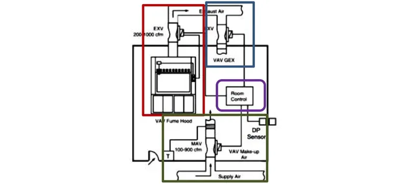
- Sash position sensor — reports opening height in real time
- Differential pressure transmitter — Deiiang CCY11, 0.25% FS, 4–20 mA or RS485 output
- VAV duct damper with electric actuator — 30 N·m torque, 20 s travel, IP67
- PLC controller — SIMATIC S7-200 SMART CPU ST20, 12 digital inputs, 8 outputs
- Airflow alarm unit — triggers low-flow alerts before face velocity falls out of tolerance
- Duct velocity sensor, plus HEPA [8] or carbon filtration for recirculating systems
Deiiang service data shows semi-annual calibration maintains VAV face velocity accuracy within ±3% over 10 years of operation.
Turndown Ratios and Verified Energy Savings
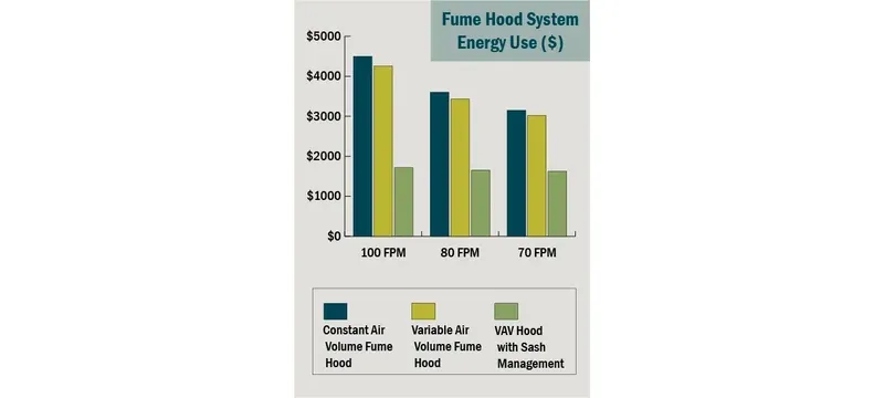
Turndown is the ratio of design airflow to minimum airflow. A 0.35 m³/s hood closing to 0.11 m³/s has a roughly 3:1 turndown ratio.
VAV-ready hoods maintain stable containment and low face velocity deviation across all sash positions, per Deiiang catalogue data.
Modern fume hood technology relies on this stability to deliver both reliable safety and measurable energy efficiency.
Field retrofits typically deliver 30–50% annual energy savings while meeting ANSI/ASHRAE 62.1 requirements [7].
Calculate annual savings using: (design airflow − average operating airflow) × annual hours × energy cost per m³ of conditioned air.
Modern Fume Hood Aerodynamics and Containment Performance
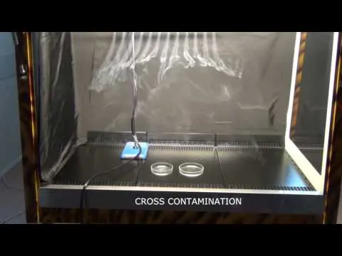
The most advanced modern fume hood technology uses baffles, airfoils and bypass openings to solve aerodynamic containment challenges.
This advance focuses on both hardware and performance verification, representing the latest stage in the evolution of fume hood design.
This section covers the design principles that allow a hood to pass the rigorous ASHRAE 110 containment test [2].
These aerodynamic advances, a key focus since the 1990s, mark another milestone on the chemical fume hood timeline.
Key Aerodynamic Design Features
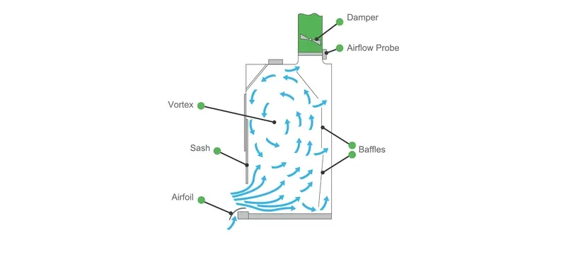
Rear baffles split exhaust into two or three slots, creating uniform airflow across the work area instead of just along the top edge.
Airfoil sash sills accelerate air past the front edge, reducing turbulence that can push vapours out into the room.
Bypass grilles open as the sash closes, limiting face velocity spikes, while sash stops prevent opening beyond safe limits.
Deiiang field teams identify three common aerodynamic failure points:
- Blocked rear baffle slots (from stored equipment) cause 40% of field containment failures
- Misaligned bypass grilles create unexpected velocity spikes at low sash heights
- Room supply vents aimed at the sash introduce high cross-draft risk
ASHRAE 110 Tracer-Gas Containment Testing
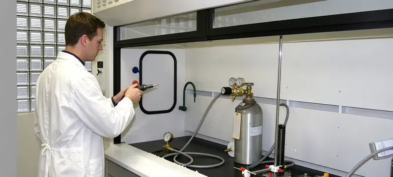
- SF6 is released at a constant rate inside the hood workspace
- Air is sampled at a mannequin’s breathing zone, with a 0.05 ppm escape threshold
- Testing runs at three sash positions: fully open, working height, fully closed
- Retesting is required after duct upgrades, hood relocation, or fan replacement
- Annual testing is standard, aligned with EN 14175 test methods [1]
A hood that releases ≤0.05 ppm at the mannequin passes containment testing under those conditions.
This closed-loop testing framework represents the current state of fume hood safety evolution.
Deiiang test engineers report 70% of failures stem from misaligned baffles, highlighting how fume hood safety evolution now prioritizes aerodynamic tuning.
Deiiang Case Study: Shared-Fan Teaching Lab VAV Retrofit
This case study examines a university analytical chemistry lab with six ducted bench-top hoods sharing a single roof-mounted fan.
It demonstrates how VAV retrofits resolve performance issues while cutting energy use and improving operational consistency.
Project Background and Core Challenges
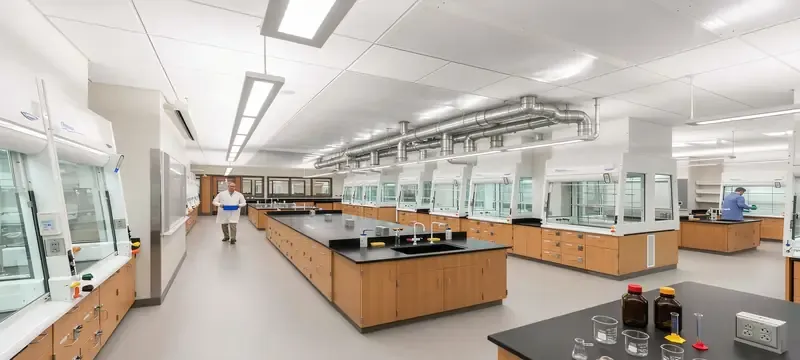
The lab faced common issues: face velocity dropped below 0.5 m/s as filters and ducts loaded, door drafts disrupted airflow, and noise rose.
All hoods ran in CAV mode on a shared fan, so individual control was impossible. Energy use stayed at maximum even with all sashes closed.
Installed Deiiang Equipment Specifications
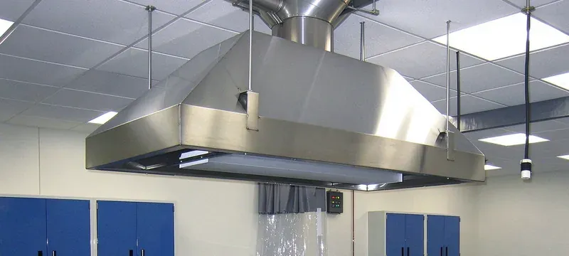
- Backdraft damper at the fan, preventing reverse flow during shutdown
- Counterweight pressure-relief damper, calibrated to 2 per mille for room pressure protection
- CAV valve on each branch, installed with 1.5× valve width of upstream straight duct
- Rectangular silencer under 800 mm on the plane side, requiring no acoustic guide vanes
- CCY11 differential-pressure transmitters on each duct, 0.25% FS accuracy
- SIMATIC S7-200 SMART PLC driving actuators and a low-flow alarm system
Measured Post-Retrofit Performance Results
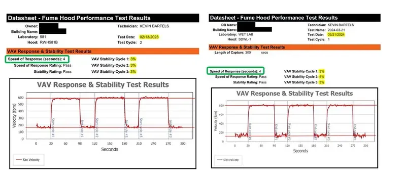
Commissioning results showed all six branches maintained design volume within a few percent, with alarms triggering before velocity fell out of tolerance.
Table 3: Reported post-retrofit performance
| Parameter | Before retrofit | After retrofit |
|---|---|---|
| Face velocity | 0.3–0.7 m/s, fluctuating | 0.4–0.6 m/s, consistent |
| Annual energy consumption | Original | Declined by 42% (project findings) |
| ASHRAE 110 containment | Almost failed | Passed |
| Room pressure stability | Not stable | ±5 Pa |
| Operator-position noise | Above target | Fits laboratory dB(A) requirements |
| Simple payback period | Not applicable | 4.2 years (project data) |
| Parameter | Before retrofit | After retrofit |
|---|---|---|
| Face velocity | 0.3–0.7 m/s, fluctuating | 0.4–0.6 m/s, consistent |
| Annual energy consumption | Original | Declined by 42% (project findings) |
| ASHRAE 110 containment | Almost failed | Passed |
| Room pressure stability | Not stable | ±5 Pa |
| Operator-position noise | Above target | Fits laboratory dB(A) requirements |
| Simple payback period | Not applicable | 4.2 years (project data) |
These results align with typical 3.5–5 year payback periods, demonstrating the real-world value written into modern VAV fume hood history.
Equipment Distinction: Fume Hood vs. clean bench vs. BSC
A fume hood protects the operator, a clean bench protects the product, and a biosafety cabinet does both. Confusing these is a common industry mistake.
Deiiang manufactures fume hoods and laminar flow clean benches, but does not produce biosafety cabinets or glove boxes.
Understanding these distinctions helps contextualize the broader history of fume hood specialization across different laboratory types.
Early fume hood design made no such distinctions, as all early setups served only basic exhaust functions.
These clear device distinctions emerged as research diversified, another key marker on the chemical fume hood timeline.
Protection Boundary Core Definitions
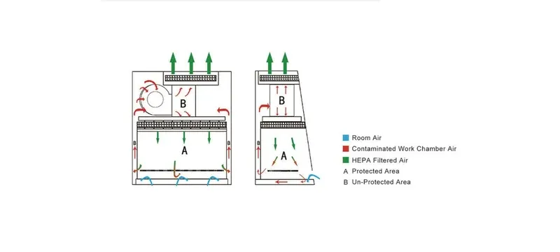
A fume hood pulls room air toward the operator, exhausting contaminants before they can reach the worker. Samples receive no product protection.
A clean bench works in reverse: it blows HEPA-filtered air across the work surface toward the operator, protecting samples but not the user.
A Class II biosafety cabinet combines both functions, and cannot be replaced by either a fume hood or a clean bench alone.
Deiiang clean bench designs meet both iso 14644-1 and China’s GB 50243-2016 ventilation standards [10][11].
Side-by-Side Equipment Comparison Table
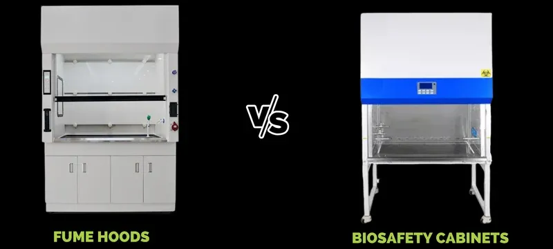
Table 4: Equipment protection comparison
| Equipment | Operator protection | Product protection | Airflow direction | Standard | Manufacturer |
|---|---|---|---|---|---|
| ducted fume hood | Yes | No | Air from room in and out | EN 14175 [1] | Deiiang: steel, PP, stainless steel and ductless hoods |
| Clean bench | No | Yes | HEPA air across bench, out to room | ISO 14644-1 [11] | Deiiang: vertical and horizontal laminar flow |
| Class II BSC | Yes | Yes | Recirculated and exhausted air | EN 12469 / NSF 49 | Not manufactured by Deiiang |
| Glove box or isolator | Yes | Yes | Kept air-tight | Application-specific | Not manufactured by Deiiang |
| Snorkel extractor | Partial | No | Local capture at source | ANSI/AIHA Z9.5 [4] | Not a Deiiang product |
| Equipment | Operator protection | Product protection |
|---|---|---|
| Ducted fume hood | Yes | No |
| Clean bench | No | Yes |
| Class II BSC | Yes | Yes |
| Glove box or isolator | Yes | Yes |
| Snorkel extractor | Partial | No |
Deiiang project data shows 80% of analytical chemistry labs choose ducted fume hoods, paired with clean benches for sample prep in microbiology labs.
Frequently Asked Questions
When were fume hoods invented for commercial laboratory use?
The first functional prototypes date to the 1880s — the decade when were fume hoods invented as enclosed devices — but commercial production began only in the 1920s.
After World War II, fume hoods became standard equipment across industrial and academic laboratory settings.
What drove the evolution of fume hood from CAV to VAV?
The 1970s energy crisis made constant-volume ventilation prohibitively expensive to operate long-term.
Cheaper sensors, PLCs and modulating actuators later made variable airflow reliable, improving safety while cutting HVAC costs.
What is the required face velocity for a standard fume hood?
SEFA 1 and EN 14175 together specify approximately 0.4–0.6 m/s, equal to around 80–120 fpm.
Exact values depend on chemical risk level, hood type, and any room cross-draft conditions present.
Does a fume hood protect work samples from contamination?
No. A laboratory hood is designed principally to protect the user operating it from harmful fumes and vapours.
While it removes vapours via negative-pressure exhaust, it offers no sample protection, so a clean bench is needed instead.
How often should fume hood containment performance be tested?
Annual ASHRAE 110 tracer-gas testing, aligned with EN 14175 requirements [1], is the accepted industry baseline.
Annual testing is a routine that reflects ongoing progress in fume hood safety evolution and performance accountability.
Any modification or relocation requires retesting, and quarterly visual inspections of sash, baffle and alarms are recommended.
Can existing CAV fume hoods be retrofitted to VAV?
Yes, but not every hood is suitable. Deiiang retrofit kits are available, but site conditions must be assessed first.
A 3:1 turndown ratio is a realistic starting target for most viable retrofit projects.
These retrofit options build on engineering principles rooted in laboratory fume hood origins and decades of iterative improvement.
Unlike early fume hood design, modern cabinet architectures support modular upgrades and targeted performance retrofits.
Retrofit solutions represent the latest chapter on the chemical fume hood timeline of iterative safety and efficiency innovation.
Retrofit capabilities add another important chapter to the broader history of fume hood advancement and adaptability.
Before undertaking the conversion, perform these steps:
References
- [1] EN 14175, fume cupboards, parts 1–7 — European Committee for Standardization.
- [2] ASHRAE 110, Method of Testing Performance of Laboratory Fume Hoods — ASHRAE.
- [3] SEFA 1, Laboratory Fume Hoods Recommended Practices — Scientific Equipment and Furniture Association.
- [4] ANSI/AIHA Z9.5, Laboratory Ventilation — American National Standards Institute.
- [5] OSHA 29 CFR 1910.1450, Occupational Exposure to Hazardous Chemicals in Laboratories — US Department of Labor.
- [6] NFPA 45, Fire Protection for Laboratories Using Chemicals — National Fire Protection Association.
- [7] ANSI/ASHRAE 62.1, Ventilation for Acceptable Indoor Air Quality — ASHRAE.
- [8] EN 1822 / ISO 29463, High-efficiency filters (EPA, HEPA and ULPA) — CEN and ISO.
- [9] ISO 16890, air filters for general ventilation — International Organization for Standardization.
- [10] GB 50243-2016, Code for Construction and Acceptance of Ventilation and Air Conditioning Works — China.
- [11] iso 14644-1, Classification of air cleanliness by particle concentration — International Organization for Standardization.
- [12] GB 50019, Code for Design of Heating, Ventilation and Air Conditioning — China.