+86 13638632902
 Jason@cleanroomequips.com


 MENU

This guide breaks down the fume hood working principle, the fume hood airflow system, and the fume hood exhaust process step by step.
The article is addressed to GMP laboratories, QC laboratory tables, and research labs.
Deiiang Cleanroom Technology supplies air regulation devices, filters, sensors and hardware around the hood. Designer Jason.peng calls this containment through the room.
Note that Deiiang produces airflow devices such as filters and dampers. All product references refer only to catalogue offerings, not hood bodies.
Core Fume Hood Working Principle
The core fume hood working principle is containment by airflow. The hood is not a sealed box. It uses a moving air curtain and pressure difference to capture hazards at the source.
A chemical fume hood mechanism depends on fume hood negative pressure, directional airflow, and an exhaust fan. Air crosses the work surface, enters baffles, and leaves the room.
Fundamental Chemical Fume Hood Mechanism
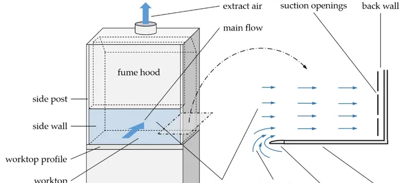
The enclosure is the first barrier. The sash, side walls, worktop, and baffles form a partial box that limits escape.
Inward airflow is the second barrier. Room air flows in front of the fume hood at a fixed velocity, usually about 0.5 m/s. That stream pulls vapors into exhaust slots.
Contaminants behave according to physics. Vapors, aerosols, and fine dust are picked up before they reACH the breathing zone.
Primary containment comes from airflow direction, not smell, colour, or user guesswork. Stable fume hood negative pressure protects the user and the room.
Most lab hoods work as constant volume (CV) or variable air volume (VAV). CV hoods move fixed airflow; VAV hoods adjust fan speed as sash height changes.
Bypass hoods add an extra air grille to stabilize face velocity at small sash openings. Recirculating hoods filter air and return it to the room without ductwork.
Role of Fume Hood Negative Pressure in Containment
- Pressure differential: hood pressure is smaller than room pressure.
- Typical range: -0.05 to -0.15 in. w.g. (about -12 to -37 Pa).
- Leak prevention: inward leakage keeps vapors inside the work zone.
- Test requirement: iso 14644-3 shows how pressure and airflow should be checked [2].
Common field problem, according to Jason Peng, Deiiang lead designer: 30% of hood pressure tests sample only at the hood face. They miss duct joint leaks.
Deiiang CCY11 sensors installed at both hood plenum and duct mid-point catch gradual drift that single-point sensors miss.
A variation of 0.02 in. w.g. may seem small, but it can change containment flow.
Deiiang CCY11 differential pressure transmitters offer accuracy of 0.25% FS, 0.5% FS, or 1% FS. If duct pressure exceeds set values, the control unit can raise an alarm.
Fume Hood Airflow System
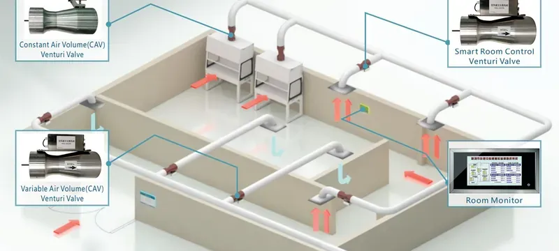
Exactly two linked paths form the fume hood airflow system: supply air and exhaust air. Face velocity, sash position, and duct pressure decide whether containment holds.
Supply air replaces the air removed by the hood. Insufficient supply may reverse room pressure and prevent the hood from working correctly.
Table 1: Comparison between supply and exhaust air in the fume hood airflow system
| Parameter | Supply side | Exhaust side |
|---|---|---|
| Air source | Room HVAC, make-up air, other supply | Hood sash opening and bypass |
| Control system | Diffusers, VAV, dampers | Baffles, CAV valves, control dampers |
| Main points | air changes, room pressure | Face velocity, duct static pressure |
| Filtration | Pre-filters, HEPA if required | Pre-filter, HEPA, carbon, scrubber |
| Risks if wrong | Cross draughts, low face velocity | Escape, re-entry, duct leakage |
| Common errors | Wrong air changes, undersized make-up air, open windows | Clogged filters, stuck dampers, duct leaks |
| Parameter | Supply side | Exhaust side |
|---|---|---|
| Air source | Room HVAC, make-up air, other supply | Hood sash opening and bypass |
| Control system | Diffusers, VAV, dampers | Baffles, CAV valves, control dampers |
| Main points | Air changes, room pressure | Face velocity, duct static pressure |
| Filtration | Pre-filters, HEPA if required | Pre-filter, HEPA, carbon, scrubber |
| Risks if wrong | Cross draughts, low face velocity | Escape, re-entry, duct leakage |
| Common errors | Wrong air changes, undersized make-up air | Clogged filters, stuck dampers, duct leaks |
Supply Air Distribution and Face Velocity Regulation
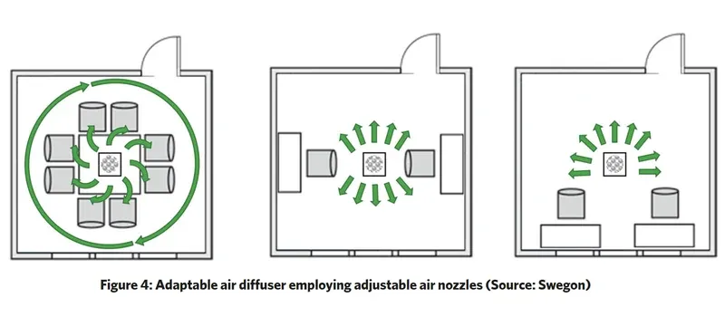
- Nominal face velocity is 0.5 m/s (about 100 fpm).
- Sash position affects how much air enters under the sash.
- Bypass air enters through a bypass grille.
- Calibration is handled by Deiiang through exhaust-side dampers, sensors, and actuators.
Face velocity is exhaust volume divided by open sash area. If a hood exhausts 0.8 m3/s through 1.6 m2, face velocity is 0.5 m/s.
Input 1: Exhaust airflow rate (m3/h)
Input 2: Sash open area = sash height x sash width (m2)
Formula: Face velocity (m/s) = (Airflow ÷ 3600) ÷ Open area
Acceptable range: 0.4–0.6 m/s for most chemical hoods.
Accurate face velocity requires 9-point grid sampling across the sash plane, per ANSI/AIHA Z9.5 [9]. Single centre readings miss low-velocity edge zones.
Jason Peng says single-point measurements overestimate face velocity by 10–20%. That was true in 40% of audited hoods.
Deiiang does not manufacture the hood body. It offers control dampers, pressure relief dampers, silencers, and CCY11 sensors for effective airflow.
Where a project uses an FH-series hood, Deiiang calibrates exhaust-side dampers and sensors, not the hood body.
Exhaust Air Filtration and Discharge Routing
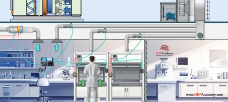
Treatment choice depends on chemical load. Pre-filtration should protect downstream HEPA or carbon stages.
HEPA filters catch particles. Deiiang catalogue H13 filters capture 99.97–99.99% at 0.3 µm. A 592 x 592 x 292 mm model handles 1900 m3/h with 15.03 m2 media.
Activated carbon captures solvent vapors and smells. Deiiang V-bank combined carbon medium filters handle 3700 m3/h.
Carbon breakthrough depends on solvent concentration, airflow rate, and adsorbent bed depth. Once media saturates, vapors pass through untreated.
Estimated service life formula: Life (hours) = (Carbon mass x Adsorption capacity) / (Airflow x Inlet concentration). Deiiang provides project-specific calculations for V-bank carbon filters.
General ventilation pre-filters fall under ISO 16890 [12].
Ductwork should be short, sealed, and routed away from air intakes. Discharge height must prevent re-entry into windows or HVAC intakes.
EU GMP Annex 1 addresses contamination control by design [3]. The fume hood exhaust process should be documented, monitored, and maintainable.
Step-by-Step Fume Hood Exhaust Process
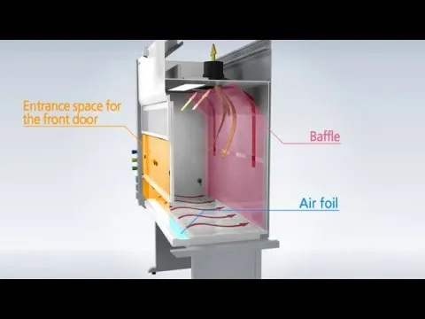
Understanding the full fume hood exhaust process is critical for troubleshooting containment failures. At each stage, part of the hazard is removed.
- Air entering through the sash: room air comes through the hood opening.
- Contaminant entrainment: vapors and particles combine with the airstream.
- Plenum mixing: air passes baffles and mixes in the duct plenum.
- Filtration treatment: pre-filters, HEPA, carbon, or scrubbers remove contaminants.
- Atmospheric discharge: cleaned air leaves through the stack.
The process fails if any stage fails. A closed damper, loaded filter, or reversed room pressure can stop containment.
Contaminant Entrainment and Plenum Dilution
Slot baffles bring air across the work surface. They reduce dead zones where heavy vapors collect.
A dead zone is a low-velocity pocket. If air moves too slowly, vapors can roll back toward the operator.
Slotted rear baffles give uniform airflow across the work surface. Solid baffles often create low-velocity pockets at the hood bottom.
Jason Peng’s project data shows equipment placed within 100 mm of rear baffles raises dead zone risk by 40%.
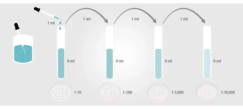
Plenum dilution mixes strong fumes with a larger air volume. A ratio of 1:100 or more lowers peak duct concentration.
Turbulence control avoids sharp bends, sudden expansions, and oversized dampers. Smooth flow keeps the chemical fume hood mechanism predictable.
Exhaust Treatment and Emission Compliance
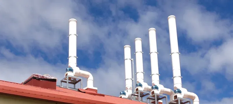
Table 2: Fume disposal technologies and compliance details
| Hazard | Treatment | Key metric | Reference |
|---|---|---|---|
| Acid gas | Wet scrubber or carbon | Removal efficiency, pH control | ACGIH TLVs + local emission regulations [6] |
| Solvent vapor | Activated carbon | Breakthrough time, dwell time | EU GMP Annex 1 [3] |
| Particulate | HEPA H13/H14 | 99.97–99.99% at 0.3 µm | EN 1822 / ISO 29463 [7] |
| Mixed waste | Pre-filter + HEPA + carbon | Pressure loss, emission limits | ISO 14644-3 [2] |
| Biological aerosols | HEPA H14 + optional UV-C | 99.995% retention at 0.3 µm; BSL alignment | iso 14644-1 / CDC BMBL [1][14] |
| Hazard | Treatment | Key metric |
|---|---|---|
| Acid gas | Wet scrubber or carbon | Removal efficiency, pH control |
| Solvent vapor | Activated carbon | Breakthrough time, dwell time |
| Particulate | HEPA H13/H14 | 99.97–99.99% at 0.3 µm |
| Mixed waste | Pre-filter + HEPA + carbon | Pressure loss, emission limits |
| Biological aerosols | HEPA H14 + optional UV-C | 99.995% retention at 0.3 µm |
Allowable acid gas emissions depend on location and hazard class. Always meet local environmental rules.
Emission limits are risk-based. A teaching hood should not use the same treatment technology as a potent-compound hood.
Laboratory Fume Hood Ventilation Design
Laboratory fume hood ventilation design balances hood exhaust, room air changes, make-up air, and duct pressure. A hood cannot work well in a room with poor ventilation balance.
Good fume hood ventilation design also keeps the fume hood airflow system stable when filters load and doors open.
air change rate and Room Pressure Balance
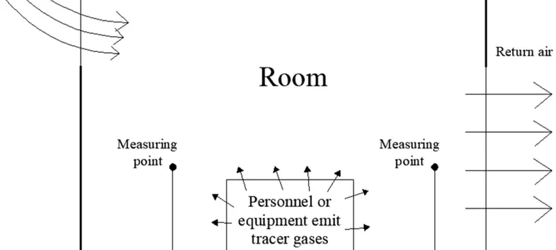
- Typical lab range: 6–12 air changes per hour (ACH).
- Room negative pressure offset: -5 to -10 Pa relative to corridor.
- Supply/exhaust ratio: often 80–90% supply to 100% exhaust.
- Deiiang project case: six hoods on a shared roof fan.
Calculation example: a 4 m x 5 m x 3 m room has 60 m3 volume. At 8 ACH, required airflow is 60 x 8 = 480 m3/h.
If six hoods exhaust 600 m3/h each, total exhaust is 3600 m3/h. Make-up air must replace that volume without creating door drafts.
Project-reported Deiiang 2024 GMP lab retrofit: six 1.8 m wide hoods on a shared roof fan. Before retrofit, face velocity drifted by ±15% as filters loaded.
After installing per-branch CAV valves and CCY11 sensors, face velocity held within ±3% of 0.5 m/s. Room pressure stabilized at -8 Pa relative to corridors.
Ductwork Design and Safety Redundancy
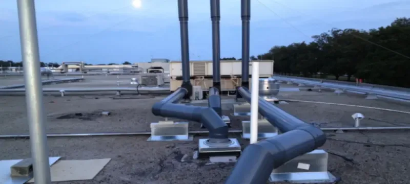
Duct material must resist the chemicals being exhausted. Common choices include stainless steel, PP, and coated steel. Duct installation should follow GB 50243-2016 / GB 50019 [13].
Explosion protection may require relief vents, spark-free fans, or grounded ductwork. NFPA 45 and OSHA 29 CFR 1910.1450 give laboratory safety guidance [4][5].
Top duct design mistake, per Jason Peng: horizontal runs longer than 5 m without slope. Condensation builds up, corrodes ducts, and unbalances airflow.
Deiiang specifies a 1° downward slope toward the hood for all exhaust ducts. This prevents liquid pooling and corrosion.
A backup exhaust fan protects critical hoods. Deiiang supplies backdraft dampers, pressure-relief dampers, CAV valves, and electric actuators for redundancy.
In a project-reported university teaching lab, six ducted hoods shared a roof fan. Face velocity fell below 0.5 m/s as filters loaded, and door cross-draughts disturbed containment.
Deiiang supplied exhaust-side hardware: a backdraft damper, a counterweight pressure-relief damper, per-branch CAV valves, a rectangular silencer under 800 mm plane side, and CCY11 transmitters read by an S7-200 SMART PLC.
Project-reported commissioning found branches holding design volume within a few percent. The low-flow alarm tripped before face velocity left tolerance, and operator-position noise met the lab target.
Proper Laboratory Fume Hood Operation
Proper laboratory fume hood operation starts before chemicals are opened. The operator should check airflow, sash position, and alarm status.
It is important to adjust and check the following:
This process should take no more than 2 minutes. It helps avoid common causes of containment failure.
Pre-Operational Safety Verification Checks
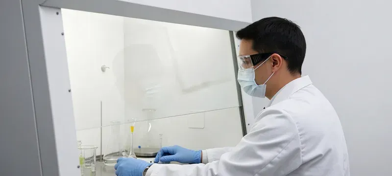
Record the result. A low face velocity often suggests filter clogging or damper malfunction.
A smoke test shows airflow direction. Hold a smoke tube near the sash edge; smoke should pull steadily into the hood.
If smoke drifts outward, face velocity is too low or room pressure is reversed. Do not handle chemicals until the problem is fixed.
Operational Best Practices for Chemical Handling
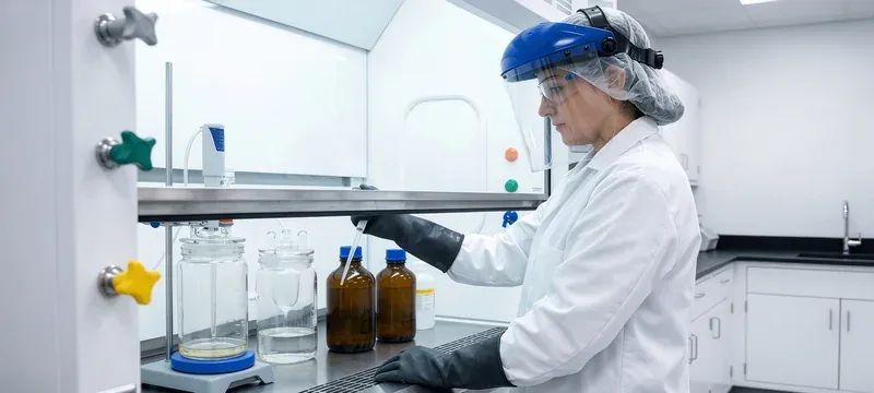
Keep the sash at or below 500 mm during work. A lower sash improves face velocity and containment.
Place work at least 150 mm inside the hood. Do not obstruct the rear baffle openings.
Never store full chemical bottles near rear baffle slots. They disturb airflow patterns and create hidden dead zones.
Jason Peng’s lab audits identify this issue in 25% of occupied chemical fume hoods.
Avoid sudden movements. Arm sweeps can create turbulence and pull vapors into the breathing zone.
Use spill collection trays and secondary containers. Clean spills immediately with compatible absorbents.
Close the sash when the hood is unattended. This reduces exhaust load and improves fume hood safety function.
Fume Hood Safety Function and Protection Features
Fume hoods serve as storage cabinets.
REALITYThey are containment devices, and stored chemicals disturb airflow.
Odour proves a hood works.
REALITYMany hazardous vapors have no smell or warning property.
Any airflow is enough.
REALITYFace velocity, pressure, and exhaust treatment must all be correct.
Active Safety Monitoring and Alarm Systems
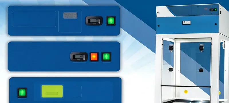
- Low airflow alarm.
- Pressure sensor alarm.
- Sash height alarm.
- Audiovisual alert.
- Data logging capability.
A low-flow alarm typically triggers at 80% of design face velocity, or 0.4 m/s for a 0.5 m/s target. Pressure alarms trigger at ±50% of the set differential.
If an alarm activates, close the sash fully and step away. Do not handle chemicals until airflow is restored and verified.
Deiiang CCY11 signals can use 4–20 mA, RS485, or 0–10 VDC. The S7-200 SMART PLC can sequence fans, dampers, and alarms.
Passive Safety and Structural Protection
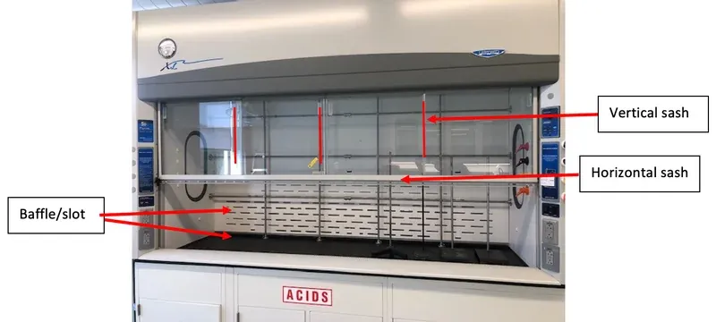
Tempered glass sash resists thermal shock and mechanical damage. A fire-resistant liner slows fire spread.
Explosion relief vents protect hoods used with flammable vapors. Chemical-resistant surfaces reduce corrosion and upkeep.
PDA Technical Report No. 34 (Risk-Based Approach to Aseptic Processing) outlines risk-based planning and verification [8].
Deiiang designer Jason Peng uses this report as the baseline for GMP fume hood risk assessments.
Frequently Asked Questions
This section answers typical questions about function, usability, compliance, and troubleshooting.
What is the correct sash height for normal fume hood operation?
A sash should be set at 400–500 mm for normal fume hood operation. This height keeps face velocity near 0.5 m/s and gives the operator working room. EN 14175 sets fume cupboard performance expectations [11].
How often should fume hood airflow performance be certified?
Certification should be annual under iso 14644-3 test methods [2] and ASHRAE 110 tracer-gas testing where needed [10]. Quarterly spot checks suit critical hoods. Retest after fan repair, duct changes, or filter replacement.
Can a fume hood work properly without dedicated make-up air?
No. Insufficient make-up air reduces face velocity and can reverse room pressure. Containment may fail even if the exhaust fan runs. Dedicated make-up air stabilizes the fume hood airflow system. In a 2023 Deiiang site audit, a lab with undersized make-up air saw hood face velocity drop to 0.28 m/s when exterior doors opened.
What is the minimum negative pressure for a chemical fume hood?
Use -0.05 in. w.g. as the minimum. Most GMP and research hoods target -0.10 in. w.g. Verify with ISO 14644-3 methods and a calibrated transmitter [2].
Do all fume hoods require HEPA filtration on the exhaust?
Not every fume hood. Particulate hazards need HEPA H13 or H14. Solvent vapors need activated carbon. Use a risk-based GMP assessment to select treatment.
How does sash position affect fume hood working principle?
A higher sash opens more space and lowers face velocity. A lower sash improves capture and containment. The optimal working range is usually 400–500 mm.
References
- [1] iso 14644-1:2015 — cleanliness classification by particle concentration.
- [2] iso 14644-3:2019 — test methods for airflow, pressure, and particle performance.
- [3] EU GMP Annex 1 — manufacture of sterile medicinal products.
- [4] NFPA 45 — fire protection for laboratories using chemicals.
- [5] OSHA 29 CFR 1910.1450 — occupational exposure to hazardous chemicals in laboratories.
- [6] ACGIH Threshold Limit Values (TLVs) and regional emission regulations.
- [7] EN 1822 / ISO 29463 — HEPA and ULPA filters.
- [8] PDA Technical Report No. 34 — risk-based approach to aseptic processing.
- [9] ANSI/AIHA Z9.5 — laboratory ventilation.
- [10] ASHRAE 110 — tracer gas containment testing.
- [11] EN 14175 — fume cupboards.
- [12] ISO 16890 — air filters for general ventilation.
- [13] GB 50243-2016 / GB 50019 — duct and HVAC installation.
- [14] CDC BMBL — biosafety in microbiological and biomedical laboratories.