1. General Provisions
This section stipulates the general requirements for the installation of duct system equipment in ventilation and air conditioning projects. The random documents of the equipment represent the product quality, as well as the installation and use instructions and technical guidance materials, and must be taken seriously.
With the continuous development of international exchanges, the installation of imported equipment in domestic projects will increase. We should, in accordance with international practice, stipulate that the installed equipment must pass the appraisal of the national commodity inspection department and have a certificate of qualified inspection.
The lifting of large, high-altitude or special equipment in rain, wind and air conditioning projects is a special process in engineering construction and is more dangerous. Any negligence may cause machine damage and injury, so it must be taken seriously.
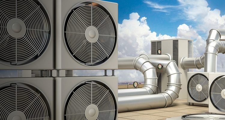
(Figure 1: Ventilation and air conditioning equipment installation)
2. Main control items
2.1 The installation of the fan shall comply with the following provisions:
The model and specification shall comply with the design requirements, and its outlet direction shall be correct:
The impeller shall rotate smoothly and should not stay in the same position every time after stopping:
The anchor bolts for fixing the fan shall be tightened and anti-loosening measures shall be taken.
Inspection quantity: full inspection.
Inspection method: check and inspect according to the design drawing.
Note: This article stipulates the main control items for the installation and acceptance of the fan. The most effective and rough method to check the quality and balance of the fan impeller installation on the project site is to rotate the impeller and observe its rotation and whether it will stay in the same position.
2.2 The external position of the fan transmission device and the inlet and outlet directly connected to the atmosphere must be equipped with a protective cover (net) or other safety facilities.
Inspection quantity: full inspection.
Inspection method: check and inspect according to the design drawing.
Note: In order to prevent accidental injury to people due to the fan, this article stipulates mandatory protective measures for the exposed parts and openings of the fan rotating parts.

(Figure 2: Ventilator fan)
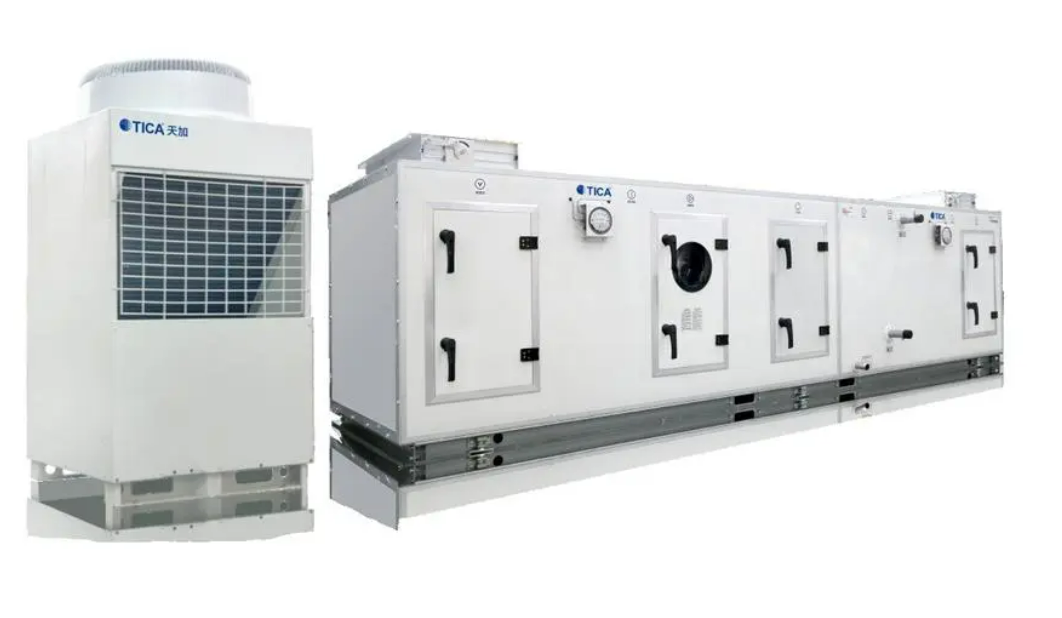
2.3 The installation of the air conditioning unit shall comply with the following provisions:
The model, specification, direction and technical parameters shall comply with the design requirements:
The combined air conditioning unit assembled on site shall be tested for air leakage, and its air leakage must comply with the provisions of the current national standard "Combined Air Conditioning Unit" GB/T 14294.
Number of inspections: 20% of the total number shall be inspected, and no less than 1 unit shall be inspected. For units of the purification air conditioning system, all units of levels 1 to 5 shall be inspected, and 50% of units of levels 6 to 9 shall be inspected.
Inspection method: Check according to the design drawings and check the test records.
Description: This article stipulates the content of the main control items for the installation and acceptance of air conditioning units. Generally, large air conditioning units are not convenient for overall transportation due to their large size, and are often transported to the site in bulk or assembled functional sections for overall assembly.
2.4 The installation of dust collectors shall comply with the following provisions:
The model, specification, and inlet and outlet directions must meet the design requirements;
The dust collector shell assembled on site shall be tested for air leakage, and the allowable air leakage rate is 5% under the design working pressure, of which the centrifugal dust collector is 3%; The shell and auxiliary equipment of bag dust collectors and electrostatic dust collectors shall be reliably grounded.
Inspection quantity: 20% of the total number shall be randomly inspected, and no less than 1 unit shall be inspected: all grounding shall be inspected.
Inspection method: check according to the drawing, check the test records and observe the inspection,
Explanation: This article stipulates the content of the main control items for the installation and acceptance of dust collectors. After the dust collector assembled on site is installed, the air leakage test of the unit shall be carried out. This article stipulates the allowable air leakage rate of the dust collector under the design working pressure.
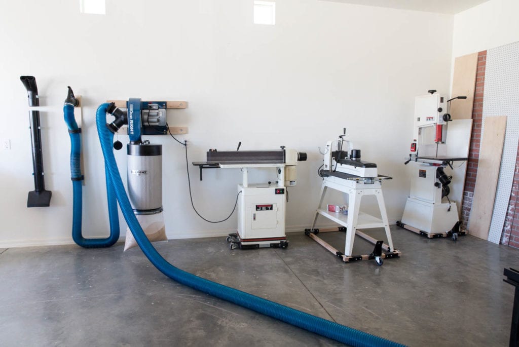
(Figure 3: Dust collector installation)
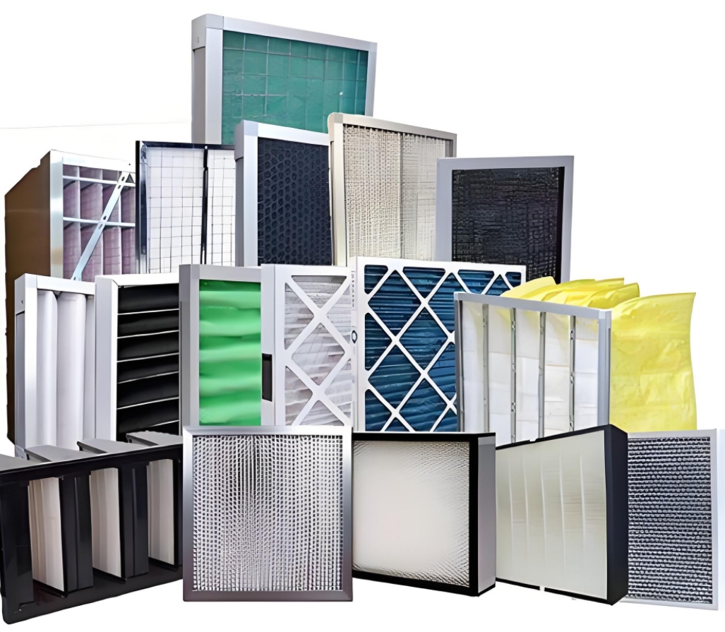
2.5 The high-efficiency filter shall be unpacked and installed on site after the clean room and the purification air conditioning system are fully cleaned and the system is continuously tested for more than 12 hours. Appearance inspection and instrument leak detection are required before installation. Visual inspection shall not show any damage such as deformation, falling off, or breaking; instrument spot check and leak detection shall comply with the provisions of the product quality documents.
Instrument spot check and leak detection of high-efficiency filters shall be 5% of the batch, and shall not be less than 1 unit.
Inspection method: Observation inspection, scanning and detection according to Appendix B of this specification, or checking the inspection records.
Note: This article stipulates the content of the main control items for the installation and acceptance of high-efficiency filters. High-efficiency filters are mainly used in clean rooms and purification air conditioning systems. The quality of their installation will directly affect the realization of the indoor air cleanliness level, so they should be implemented seriously.
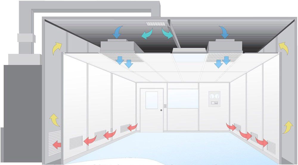
2.6 The installation of purification air conditioning equipment shall also comply with the following provisions:
The joints between the purification air conditioning equipment and the clean room enclosure structure must be sealed;
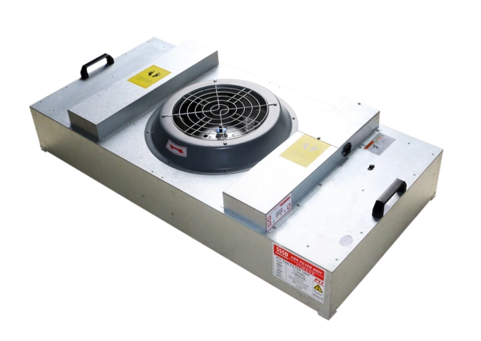
The fan filter unit (FFU and FMU air purification device) should be visually inspected at the clean site, and visual inspection shall not show deformation, rust, paint film shedding, splicing plate' damage and other phenomena; during the system trial operation, a temporary medium-efficiency filter must be installed at the air inlet as protection.
Inspection quantity: full inspection.
Inspection method: check according to the design drawing and visual inspection.
Explanation: This article stipulates the content of the main control items for the installation and acceptance of purification air conditioning equipment. Purification air conditioning equipment refers to special equipment used in air purification systems, which must be clean and tight when installed. For fan filter units, it is also emphasized that when the system is trial-operated, a medium-efficiency filter must be installed as protection.
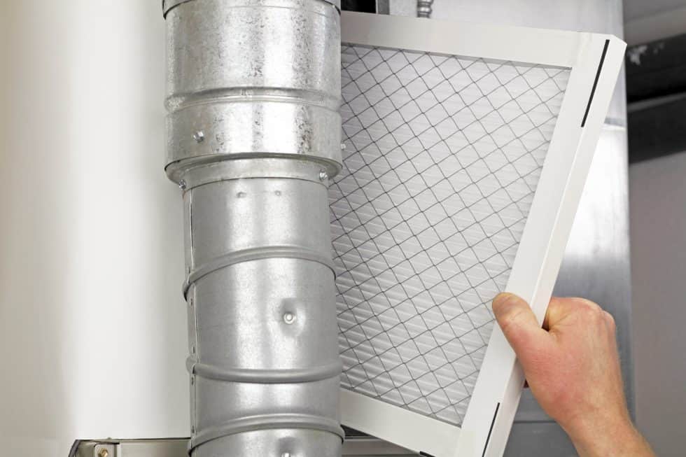
(Figure 4: High efficiency filter)
2.7 The metal shell of the electrostatic Air Filter must be well grounded.
Inspection quantity: 20% of the total number shall be randomly inspected, and no less than 1 unit shall be installed.
Inspection method: check materials, visual inspection or resistance measurement.
Note: This article stipulates that the installation of electrostatic air handling equipment must be reliably grounded.
2.8 The installation of electric heaters must comply with the following provisions:
The insulation layer between the electric heater and the steel frame must be made of non-combustible materials; safety protection devices should be added to the exposed terminal;
The metal shell of the electric heater must be well grounded:
The flange gasket of the air duct connected to the electric heater should be made of heat-resistant non-combustible materials.
Inspection quantity: 20% of the total number shall be randomly inspected, and no less than 1 unit shall be made.
Inspection method: check materials, observe and inspect or measure with electric positive.
Note: This article stipulates that the installation of electric heaters must be reliably grounded and prevent combustion.
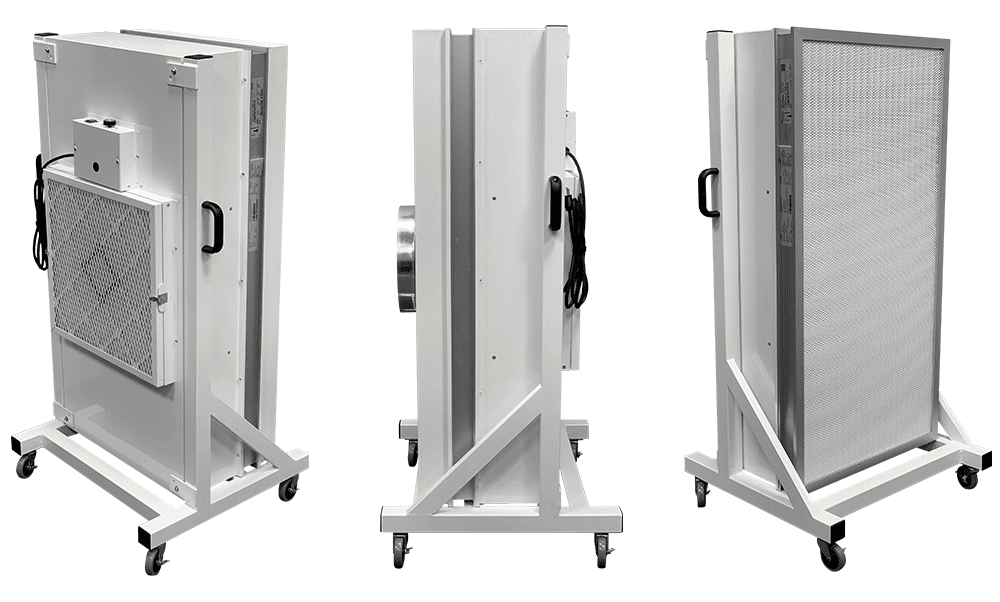
(Figure 5: FFU, FMU air purification device)
2.9 When installing dry steam humidifiers, the steam nozzle should not be facing downward.
Inspection quantity: check all.
Inspection method: observe and inspect.
Note: This article stipulates the main control items for the installation and acceptance of dry steam humidifiers. If the jet pipe of the dry steam humidifier is installed downward, the working environment for producing dry steam will be destroyed, so it is not allowed.
2.10 The installation direction of the filter absorber must be correct, and an independent bracket should be provided. The connecting pipe section with the outside must not leak.
Inspection quantity: All inspections.
Inspection method: Observation or detection.
Instructions: This article stipulates the content of the main control items for the installation and acceptance of the filter absorber. The filter absorber is an important air treatment device in civil air defense projects. It has the function of filtering and adsorbing toxic and harmful gases to ensure personal safety. If the installation is wrong, the function of the filter absorber will fail and the safe use of the system cannot be guaranteed.
3. General items
3.1 The installation of the fan shall comply with the following provisions:
The installation of the fan shall comply with the provisions of the table, and the assembly position of the impeller rotor and the casing shall be correct; the depth of the impeller air inlet inserted into the fan casing air inlet or the sealing ring shall comply with the provisions of the equipment technical documents, or be 1/100 of the impeller outer diameter value.
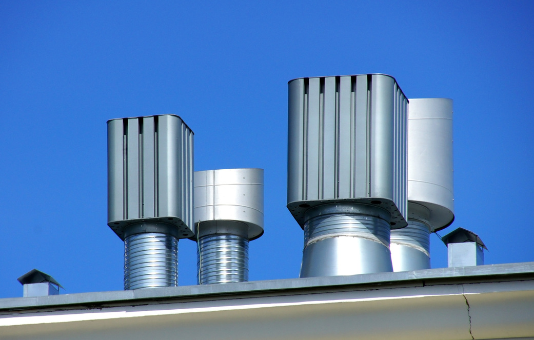
(Figure 6: Ventilator)
The installation angle of the axial flow fan blades assembled on site shall be consistent, so that they can operate in the same plane, the gap between the impeller and the cylinder shall be uniform, and the horizontality allowable deviation shall be 1/1000: the ground where the vibration isolator is installed shall be flat, the compression amount of each group of vibration isolators under load shall be uniform, and the height error shall be less than 2mm; the structural form and external dimensions of the vibration isolation steel support and hanger for installing the fan shall comply with the design. Or the provisions of the equipment technical documents; the welding shall be firm, and the weld shall be full and uniform.
Inspection quantity: 20% of the total number shall be randomly inspected, and no less than 1 unit shall be inspected.
Inspection method: measurement, observation or inspection of construction records.
Note: This article stipulates the allowable deviation of fan installation and the acceptance quality of vibration isolation bracket installation. To prevent the displacement of vibration isolators, it is stipulated that the ground for installing vibration isolators should be flat. The compression amount of vibration isolators on the same machine base should be consistent so that the vibration isolators are evenly stressed. The vibration isolators, steel supports and hangers for installing fans should be selected according to their loads and usage occasions.
| Item | Project | Permissible deviation | Inspection methods | ||
| 1 | Plane displacement of center line | 10mm | Theodolite or wire drawing and measuring | ||
| 2 | Elevation | ±10mm | Level or level, ruler, wire drawing and measuring | ||
| 3 | Pulley width center Plane offset | 1mm | Draw wire and measuring on the end faces of the driving and driven pulleys | ||
| 4 | Drive shaft horizontality | Vertical 0.2/1000 Horizontal 0.3/1000 | Check with a level at 0 and 180° on the shaft or pulley | ||
| 5 | Couplings | Two-axis core radial displacement | 0.05mm | Check with a dial indicator at four mutually perpendicular positions of the coupling | |
| Two axis tilt | 0.2/1000 | ||||
3.2 The installation of modular air-conditioning units and cabinet air-conditioning units shall comply with the following provisions:
The assembly of each functional section of the modular air-conditioning unit shall comply with the order and requirements specified in the design; the connection between each functional section shall be tight and the whole shall be straight:
The connection between the unit and the supply and return water pipes shall be correct, and the water seal height of the condensate discharge pipe at the bottom of the unit shall meet the design requirements.
The unit should be cleaned and there should be no debris, garbage and dust in the box:
The air filter (net) and air heat exchanger fins in the unit should be clean and intact.
Number of inspections: 20% of the total number shall be randomly inspected, and no less than 1 unit shall be inspected.
Inspection method: Observation inspection.
Explanation: This article stipulates the acceptance quality of the installation of combined air-conditioning units. The assembly and arrangement of functional sections of the combined air-conditioning units shall comply with the design requirements, and also require the overall straightness of the unit appearance, tight connection between functional sections, cleanliness and good equipment protection.
3.3 The installation of the air handling room shall comply with the following regulations:
The assembly of metal air handling room wall panels must be correct, with flat surfaces and tight connections. The water spray section and inspection door must be leak-proof, and the arrangement of water spray pipes and nozzles must meet design specifications.
The heat exchanger's surface should remain clean and intact. A drainage device must be installed at the bottom for cooling air, ensuring that the drainage pipe is unobstructed to prevent overflow.
Gaps between the heat exchanger and the enclosure, as well as between heat exchangers, should be sealed tightly. Connections between the heat exchanger and supply/return pipes must be correct and leak-free.
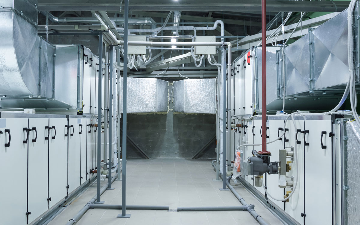
(Figure 7: Metal air handling chamber)
Inspection quantity: 20% of the total number should be randomly inspected, and no less than 1 unit should be inspected.
Inspection method: Observation inspection.
Explanation: This article stipulates the acceptance quality of the installation of the air handling room assembled on site. The parts of the air handling room assembled on site that are prone to water leakage are mainly the embedded pipes, inspection doors, water pipe interfaces, and assembly joints of the water spray section. Attention should be paid to them during the construction quality acceptance.
The gold fins of the surface heat exchanger are easily damaged and contaminated during transportation and installation, which will increase air resistance and affect heat exchange efficiency. Therefore, the article also made corresponding provisions to prevent similar situations from happening.
3.4 The installation of unit air-conditioning units shall comply with the following provisions:
The installation and fixation of the outdoor unit of the split air-conditioning unit and the air-cooled integral air-conditioning unit shall be firm and reliable; in addition to meeting the requirements of the cooling air circulation space, it shall also comply with the provisions of relevant laws and regulations on environmental sanitation protection.
The position of the indoor unit of the split air-conditioning unit shall be correct and level, and the condensate discharge shall be unobstructed. The pipe penetration must be sealed and no rainwater shall penetrate; the connection of the integral air-conditioning unit pipe shall be tight and leak-free, and corresponding maintenance space shall be left around.
Inspection quantity: 20% of the total number shall be randomly inspected, and shall not be less than 1 unit.
Inspection method: Observation inspection.
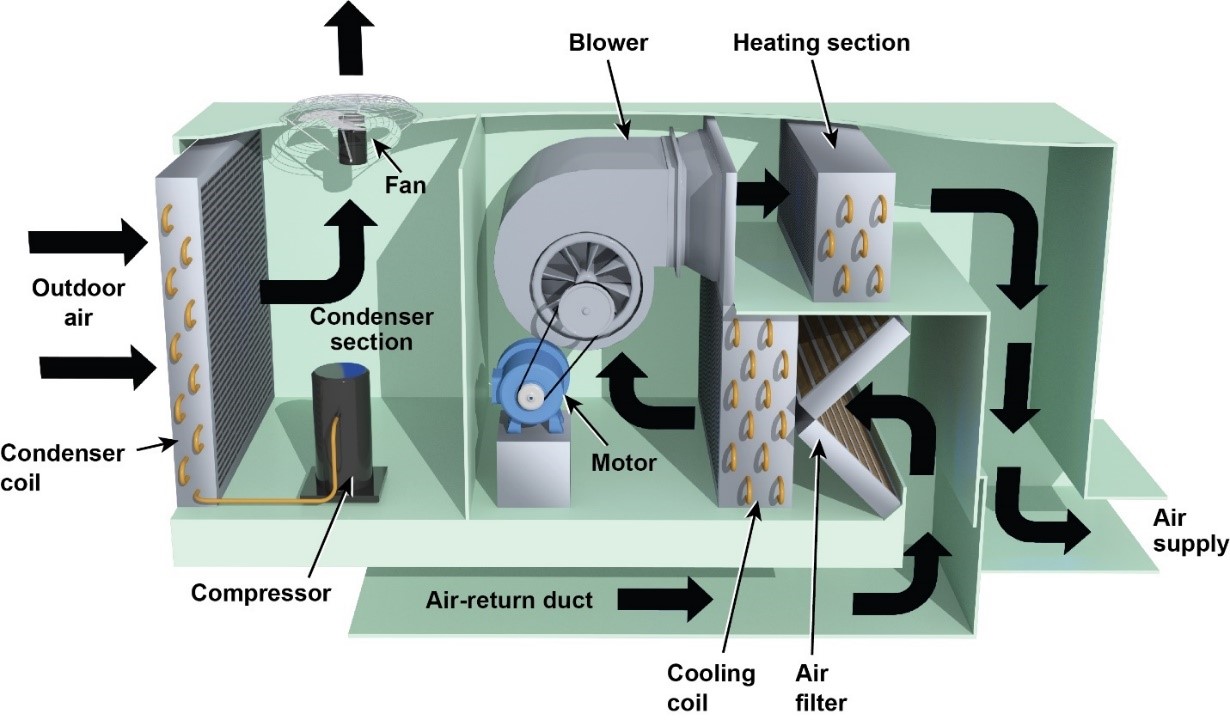
(Figure 8: Unitary air conditioning unit)
Note: This article is for the installation of split air conditioners and air-cooled integral air conditioners, and puts forward quality acceptance requirements.
3.5 The installation of dust removal equipment shall comply with the following provisions:
The installation position of the dust collector shall be correct, firm and stable, and the allowable error shall comply with relevant regulations.
The movement of the movable or rotating parts of the dust collector shall be flexible and reliable, and shall meet the design requirements. The dust collector's ash discharge valve, discharge valve, and mud discharge valve should be installed tightly and convenient for operation, maintenance, and repair.
Inspection quantity: 20% of the total number shall be randomly inspected, and shall not be less than 1 unit. Inspection method: measurement, observation inspection, and inspection of construction records.
Description: This article stipulates the general acceptance quality of various types of dust collector installation. The correct installation position of the dust collector can ensure the smooth connection of the air duct. The installation quality of the dust collector is closely related to the dust removal efficiency. This article makes specific provisions on the allowable deviation and inspection method of the dust collector installation.
3.6 The installation of electrostatic precipitators assembled on site shall also comply with the technical documents of the equipment and the following provisions:
The flatness allowable deviation of the anode row after the anode plate is combined is 5mm, and the diagonal allowable deviation is 10mm;
The flatness allowable deviation of the main plane after the cathode small frame is combined is 5mm, and the diagonal allowable deviation is 10mm;
The overall flatness allowable deviation of the cathode large frame is 15mm, and the overall diagonal allowable deviation is 10mm;
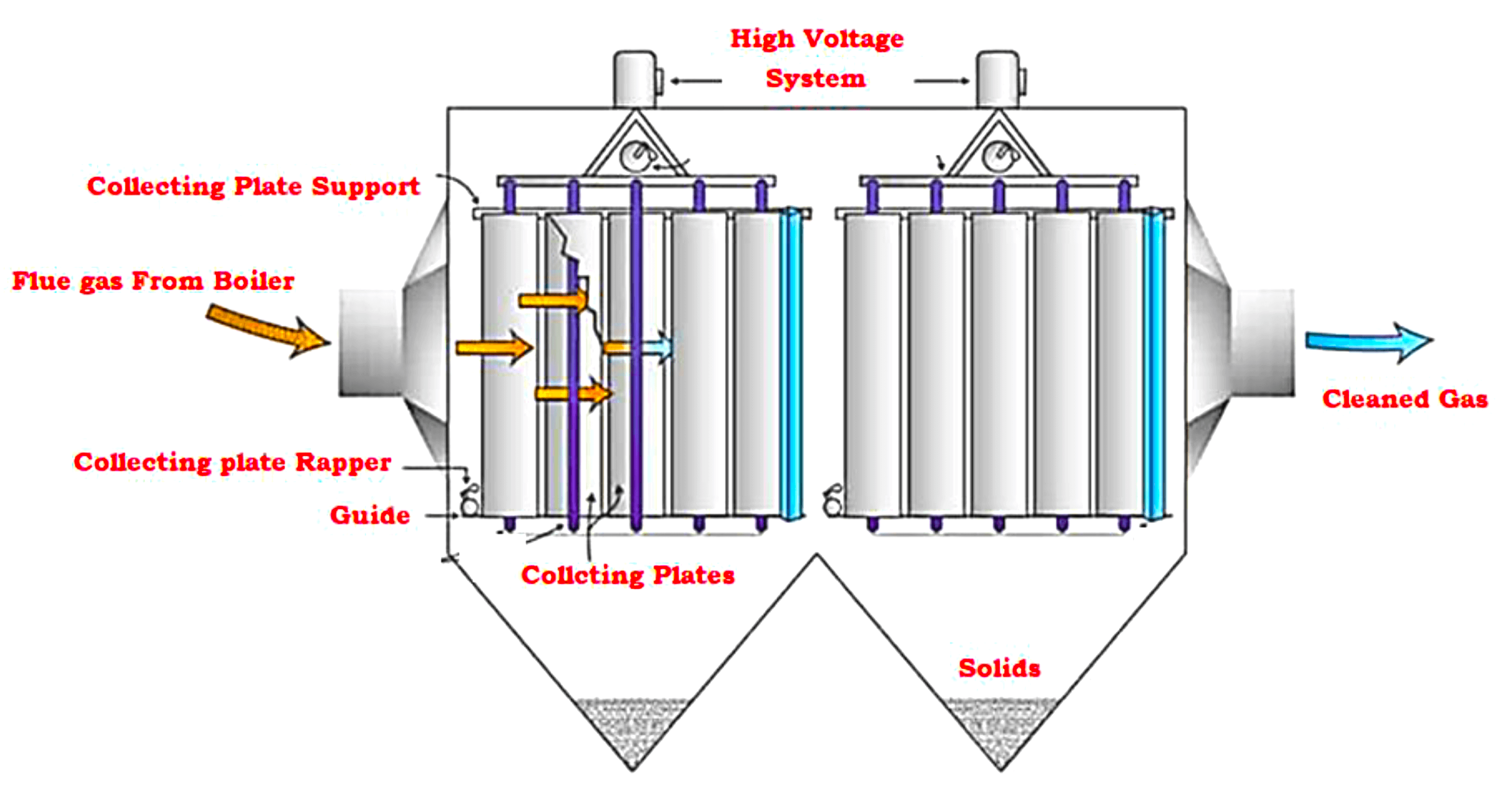
(Figure 9: Electrostatic precipitator)
For electrostatic precipitators with anode plate height less than or equal to 7m, the allowable deviation of the distance between the cathode and anode is 5mm. For electrostatic precipitators with anode plate height greater than 7m, the allowable deviation of the distance between the anode and the anode is 10mm;
The fixing of the rapping hammer device should be reliable; the rotation of the rapping hammer should be flexible. The direction of the hammer head should be correct; the rapping hammer head and the rapping anvil should maintain a good linear contact state, and the contact length should be greater than 10.7 times the thickness of the hammer head.
Inspection quantity: 20% of the total number shall be randomly inspected, and no less than 1 group shall be allowed.
Inspection method: measurement, observation and inspection of construction records.
Note: For electrostatic precipitators assembled on site, this article emphasizes the installation quality of the cathode and anode electrode plates.
3.7 The installation of bag dust collectors assembled on site shall also comply with the following regulations:
The outer shell should be tight and leak-proof, and the bag interface should be firm:
The filter bag installation of the chamber back-blowing bag dust collector must be straight. The tension of each bag should be maintained at 25~35N/m; the short pipe and bag singing in contact with the filter bag should be free of burrs:
The swing arm of the mechanical rotary flat bag bag dust collector should rotate flexibly and reliably, the top cover on the top of the Clean air chamber should be sealed and leak-proof, and the rotation should be flexible and free of jamming;
The injection hole of the bag dust collector in the pulse should be aligned with the center of the Venturi tube, and the concentricity allowable deviation is 2mm.
Inspection quantity: 20% of the total number shall be randomly inspected, and no less than 1 unit shall be inspected.
Inspection method: measurement, observation and inspection of construction records.
Note: The acceptance of the on-site assembled bag dust collector should mainly control the installation quality of its shell, bag and mechanical dust removal device.
3.8 The installation of clean room air purification equipment shall comply with the following regulations:
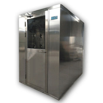
There should be a vibration isolation pad between the airlock room and the shower with a ventilator and the ground:
When installing the mechanical residual pressure valve, the rotating shaft of the valve body and the valve plate should be horizontal, and the allowable deviation is 2/1000. The installation position of the residual pressure valve should be on the leeward side of the indoor airflow and should not be within the working surface height range:
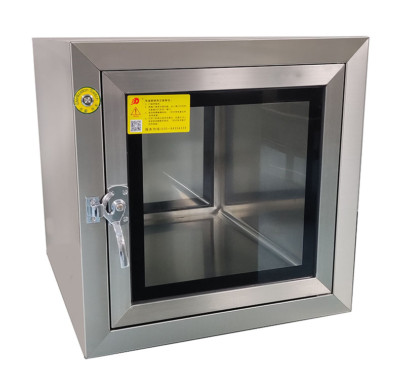
The installation of the transfer element should be firm and vertical, and the connection with the body should be sealed.
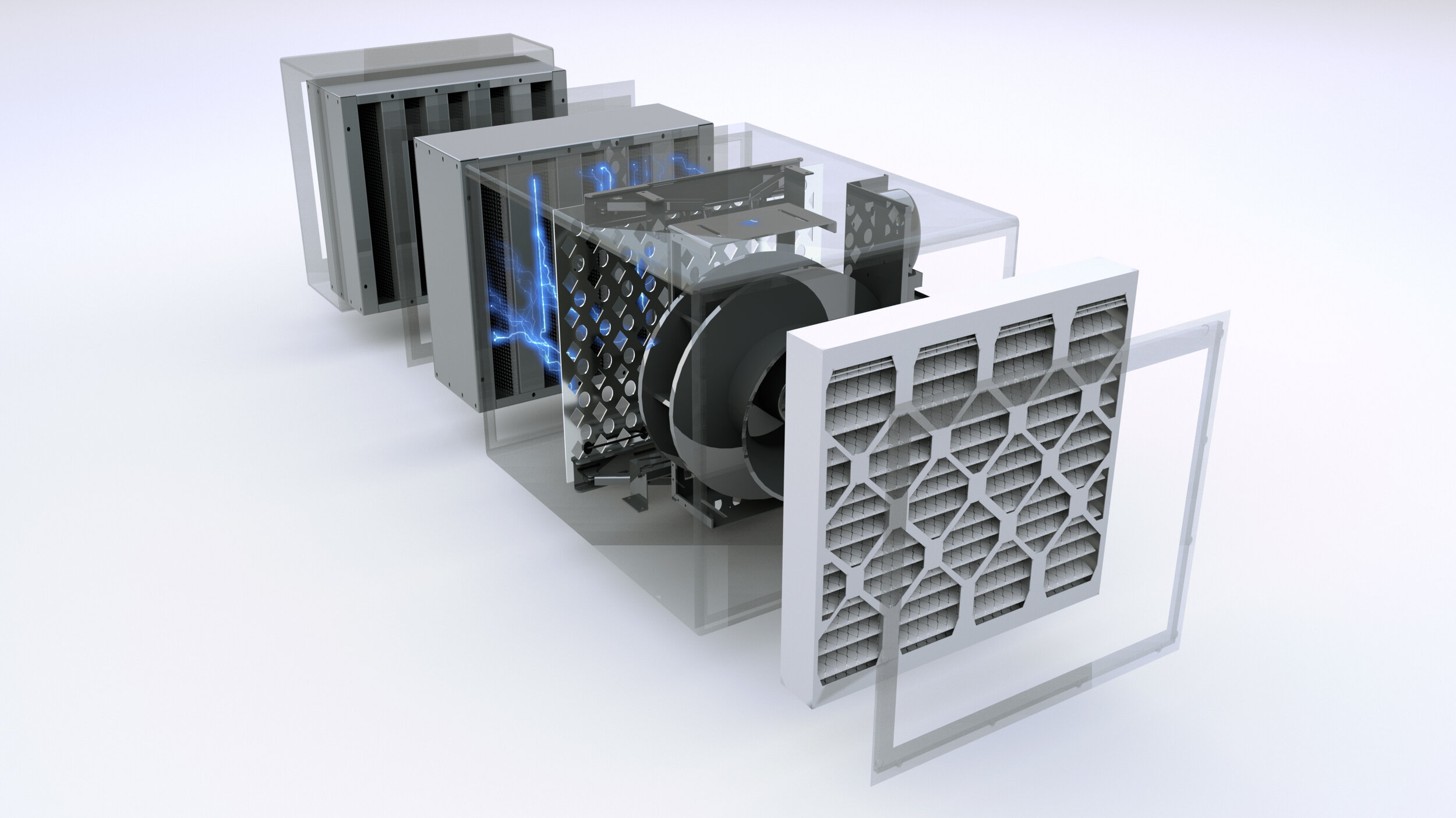
(Figure 10: Clean room air purification Equipment)
Inspection quantity: 20% of the total number shall be randomly inspected, and shall not be less than 1 piece.
Inspection method: measurement, observation inspection,
Note: This article stipulates the acceptance quality of the installation of clean equipment in the purification air conditioning system. The vibration of the airlock room and shower with a ventilator will have an adverse effect on the environment of the clean room. Therefore, vibration isolation pads are required. The acceptance of the installation quality of mechanical residual pressure valves and transfer windows emphasizes the horizontality and sealing.
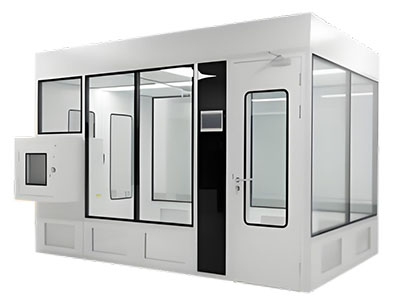
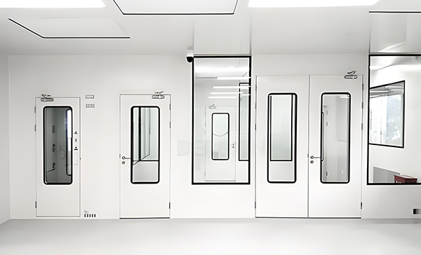
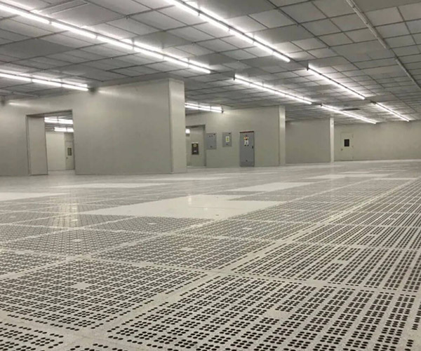
3.9 The installation of prefabricated Clean Rooms shall comply with the following provisions:
The ceiling and wall panels (including sandwich materials) of the clean room shall be non-combustible materials:
The floor of the clean room shall be dry and flat, and the allowable deviation of flatness is 1/1000:
The unpacking of the components and auxiliary materials of the wall panels shall be carried out in A Clean Room, and their specifications and quality shall be strictly checked before installation. The wall panels shall be installed vertically, and the bottom shall be connected with an arc or obtuse angle; the joints between the wall panels and the ceiling panels after installation shall be flat and tight, and the vertical allowable deviation of the panel is 2/1000, and the allowable deviation of the ceiling horizontality and the allowable deviation of the geometric dimensions of each single room are both 2/1000:
The ceiling of the clean room shall remain straight after being loaded, and all the pressure strips shall be tightly attached. If the Clean room wall panels are upper and lower truss-shaped panels, their joints should be flat and tight; all joints of the assembled clean room, including the joints with the building, should be sealed to prevent them from falling off and to ensure good sealing.
Inspection quantity: 20% of the total number shall be randomly inspected, and shall not be less than 5.
Inspection method: measurement, observation inspection and inspection of construction records.
Explanation: This article outlines the acceptance criteria for installing prefabricated clean rooms to ensure safe use. It specifies that the top and wall plates must be made of non-combustible materials, and the clean room floor should be dry and flat to support surface coatings and materials.

(Figure 11: Clean laminar flow hood)
To control assembly quality, it addresses the vertical alignment of wall and pond panels, the horizontal alignment of the top plate, and allowable dimensional deviations for each room. It emphasizes the importance of neat, tight joints at the ceiling and wall interfaces, which must remain flat under load. Proper sealing and joint quality are critical for maintaining cleanliness and achieving pressure control in the clean room.
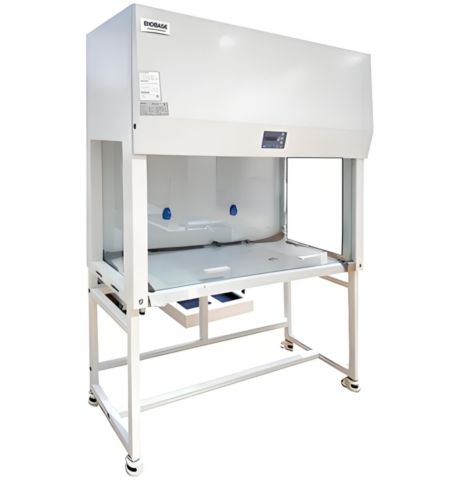
3.10 The installation of the clean laminar flow hood shall comply with the following provisions:
An independent suspension rod shall be set up, and anti-sway fixing measures shall be taken:
The horizontal deviation of the laminar flow hood installation is allowed to be 1/1000, and the height deviation is allowed to be 1mm;.
The laminar flow hood is installed on the ceiling, and sealing and vibration isolation measures shall be provided between its surroundings and the top plate.
Inspection quantity: 20% of the total number shall be randomly inspected, and shall not be less than 5 pieces.
Inspection method: measurement, observation inspection and inspection of construction records.
Explanation: This article stipulates the acceptance quality of the installation of clean laminar flow hoods in purification air conditioning systems.
3.11 The installation of fan filter units (FFU, FMU) shall comply with the following provisions:
The high-efficiency filter of the fan filter unit shall be leak-checked in accordance with the provisions of this specification before installation, and shall be installed after passing the inspection. The direction must be correct; the installed FFU or FMU unit shall be easy to repair;
The installed FFU fan filter unit shall be kept flat as a whole and well connected with the ceiling. The connection between the fan box and the filter, and between the filter unit and the ceiling frame shall have reliable sealing measures.
Inspection quantity: 20% of the total number shall be randomly inspected, and shall not be less than 2.
Inspection method: measurement, observation inspection and inspection of construction records.
Note: This article stipulates the acceptance quality of the installation of the fan filter unit in the purification air conditioning system.

(Figure 12: Installation of the muffler)
3.12 The installation of the high-efficiency filter shall comply with the following provisions:
When the high-efficiency filter adopts mechanical sealing, a sealing gasket with a thickness of 6~8mm shall be used, and it shall be positioned and attached to the filter frame. After installation, the compression of the hot material shall be uniformly compressed at a rate of 25%6-50%:
When the liquid tank is sealed, the frame shall be installed horizontally, without leakage, no dirt and moisture inside, and the height of the internal sealing liquid shall be 2/3 deep. The melting point of the sealing liquid shall be higher than 50℃
Inspection quantity: 20% of the total number shall be randomly inspected, and shall not be less than 5.
Inspection method: measurement and observation inspection.
Note: This article stipulates the acceptance quality of the installation of the high-efficiency filter in the purification air conditioning system. When the high-efficiency filter adopts mechanical sealing, the thickness of the sealing gasket and the installation joint treatment are very important. The thickness shall be implemented in accordance with the provisions of the article, and the connection shall not be directly connected.
3.13 The installation of the muffler shall comply with the following regulations:
The muffler should be kept clean before installation, free of oil and dust:
The installation position and direction of the muffler should be correct, and the connection with the air duct should be tight, without damage and moisture. Two groups of mufflers of the same type should not be directly connected in series; the arrangement, direction and position of the muffler components of the combined muffler installed on site should meet the design requirements.
Inspection quantity: For the mufflers installed as a whole, 10% of the total number shall be randomly inspected, and no less than 5 units shall be provided. All the mufflers assembled on site shall be inspected.
Inspection method: manual inspection and observation inspection, verification of installation records,
Note: This article stipulates the acceptance quality of the muffler installation. The article emphasizes that an appearance inspection should be done before the installation of the muffler; during the installation process, attention should be paid to protection and moisture-proofing. Many mufflers have directional requirements for installation and cannot be installed in the opposite direction. The volume and weight of the muffler and the muffler elbow are large, and separate supports and hangers should be set up.
3.14 The installation of the air filter shall comply with the following regulations:
The installation is flat, firm, and in the correct direction. There should be no penetration seams between the filter and the frame, and between the frame and the enclosure structure;
For the installation of full-frame or coarse-effect and medium-effect bag air filters, the filter and the frame should be evenly pressed around, without visible gaps, and it should be easy to disassemble and replace the filter material; for the installation of the winding filter, the frame should be flat, the unfolded filter material should be moderately tight, and the upper and lower cylinders should be parallel.
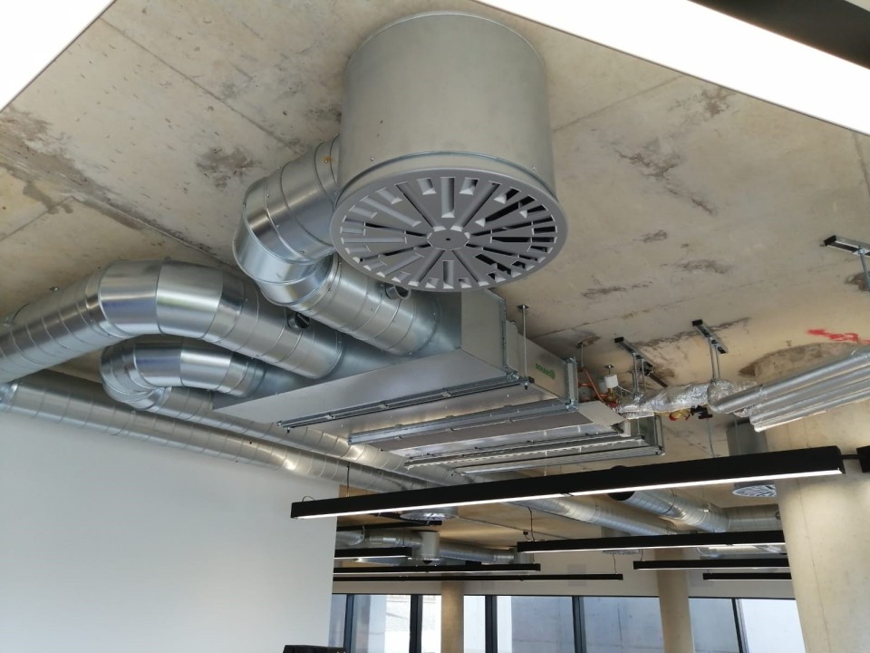
(Figure 13: Installation of fan coil units)
Inspection quantity: 10% of the total number shall be randomly inspected, and no less than 1 unit shall be required.
Inspection method: visual inspection.
Note: This article stipulates the acceptance quality of air filter installation.
If the air filter and the frame, or the frame and the enclosure structure are not sealed tightly, it will affect the dust removal effect of the filter, so it is required that there is no penetrating gap during installation.
The installation of the roll-type filter should be flat, and the upper and lower cylinders should be parallel to achieve consistent tightness of the material and prevent material leakage during use.
3.15 The installation of fan coil units shall comply with the following provisions:
Before installing the unit, a single unit three-speed test run and water pressure leak test should be carried out. The test pressure is 1.5 times the system working pressure, the test observation time is 2 minutes, and no leakage is qualified:
The unit should be equipped with independent supports and hangers, and the installation position, height and slope should be correct and firmly fixed:
The connection between the unit and the air duct, return air box or air outlet should be tight and reliable.
Inspection quantity: 10% of the total number shall be randomly inspected, and no less than 1 unit shall be inspected.
Inspection method: Observation inspection, review of inspection test records.
Explanation: This article stipulates the acceptance quality of fan coil air conditioner installation. Before installing the fan coil unit, it is advisable to conduct a random inspection of the product quality, so that the quality of the project can be effectively controlled and problems can be found after installation to avoid rework. When installing the fan coil unit, attention should also be paid to the control of the horizontal slope. Improper slope will affect the normal discharge of condensed water.
3.16 The installation position, rotation direction of the impeller and the pipe connection of the rotary heat exchanger should be correct and the operation should be smooth.
Inspection quantity: 20% of the total number shall be randomly inspected, and no less than 1 unit shall be inspected.
Inspection method: Observation inspection.
Explanation: This article stipulates the acceptance quality of the installation of the rotary heat exchanger.
The article emphasizes that the air duct connection must not be wrong to prevent functional failure and system air pollution.

(Figure 14: Installation of rotary heat exchanger)
3.17 The rotary dehumidifier should be installed firmly, the impeller and transmission parts should be flexible, reliable and in the correct direction; the treatment air and regeneration air pipes should be connected correctly; the exhaust horizontal pipe must maintain a certain slope and slope towards the discharge direction.
Inspection quantity: 20% of the total number shall be randomly inspected, and no less than 1 unit shall be inspected.
Inspection method: Observation inspection.
Explanation: This article stipulates the acceptance quality of the installation of the rotary dehumidifier.
3.18 The installation of steam humidifiers should be equipped with independent brackets and fixed firmly; the size of the pipes should be correct and there should be no sea leakage.
Inspection quantity: full inspection,
Inspection method: observation inspection,
Description: This article stipulates the acceptance quality of steam humidifier installation. In order to prevent unnecessary vibration during the use of steam humidifiers, independent brackets should be set and fixed firmly.
3.19 The installation of air curtains should be correct, firm and reliable in position and direction, and the deviation of longitudinal verticality and lateral horizontality should not be greater than 2/1000.
Inspection quantity: spot check at a ratio of 10% of the total number, and no less than 1 unit.
Inspection method: observation inspection.
Description: This article stipulates the acceptance quality of air curtain installation.
3.20 When installing the variable air volume terminal device, a separate support and hanger should be set up, and an action test should be performed before connecting it to the air duct.
Inspection quantity: 10% of the total number shall be randomly inspected, and no less than 1 unit shall be inspected.
Inspection method: Observation inspection, review of inspection and test records.
Explanation: This article stipulates the acceptance quality of the installation of the variable air volume terminal device. The variable air volume terminal device should be equipped with a separate support and hanger for easy adjustment and maintenance; an action test should be performed before connecting it to the air duct, and the seal should be made after confirming that it is operating normally, which can ensure the normal operation of the equipment after installation.
 +86 18186671616
 Jason@cleanroomequips.com
 MENU
MENU

