+86 13638632902
 Jason@cleanroomequips.com
 MENU
MENU

Introduction: Cleanroom's "Lifeline" - Airflow
Effective Cleanroom airflow management is the cornerstone of contamination control in critical environments. This comprehensive guide explores the fundamental principles that govern cleanroom ventilation systems and their impact on operational performance.
Understanding proper Cleanroom airflow dynamics is essential for maintaining ISO classification compliance while optimizing energy efficiency. The strategic implementation of these principles directly impacts product quality and process reliability across multiple industries.
Cleanroom Airflow Basics: Why Is It So Critical?
Proper Cleanroom airflow design begins with understanding the fundamental relationship between air movement patterns and contamination control. This relationship determines the effectiveness of particle removal and distribution throughout the controlled environment.
The implementation of optimized Cleanroom airflow systems requires careful consideration of multiple factors including room geometry, equipment placement, and process requirements. These elements collectively determine the success of contamination control strategies.
What is Cleanroom Airflow? Definition & Core Objectives
Cleanroom airflow refers to the controlled movement of filtered air through a clean environment to remove airborne contaminants. The primary objective is maintaining specific cleanliness levels by controlling particle concentration through strategic air distribution patterns.
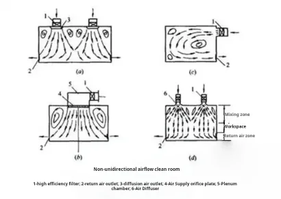
Figure 1: Cleanroom airflow removing contaminants from critical areas
Impact of Airflow on Cleanliness Levels
Airflow patterns directly influence particle distribution and settlement rates. For example, in a properly designed iso class 5 environment, particles larger than 0.5μm are maintained below 3,520 particles per cubic meter through controlled Cleanroom airflow management.
Key Metrics: air changes Per Hour (ACH) & Air Velocity
The Air Change Rate (ACH) calculation follows this formula: ACH = (Airflow Rate in m³/h) / (Room Volume in m³). For an iso class 7 cleanroom with dimensions 10m × 8m × 3m (240m³), achieving 60 ACH requires an airflow rate of 14,400 m³/h (240 × 60).
| ISO Class | Recommended ACH | Air Velocity (m/s) |
|---|---|---|
| iso 5 | 240-600+ | 0.45 ± 20% |
| ISO 6 | 90-150 | N/A |
| ISO 7 | 30-70 | N/A |
| iso 8 | 10-25 | N/A |
Table: ISO 14644-1 Cleanliness Classes with recommended ACH and air velocity values
Cleanroom Airflow Patterns: Types, Design & Application
The selection of appropriate Cleanroom airflow patterns represents a critical decision in facility design, with significant implications for both performance and operating costs. Different patterns offer distinct advantages for specific applications.
Proper implementation of Cleanroom airflow patterns requires understanding the relationship between air movement direction, velocity profiles, and contamination control effectiveness. Each pattern offers unique benefits for specific operational requirements.
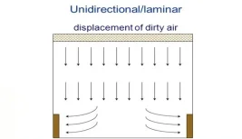
Unidirectional Flow/Laminar Flow Cleanrooms
Unidirectional airflow systems maintain parallel streamlines with minimal cross-contamination. In vertical laminar flow systems, air typically moves downward at 0.45 m/s ±20%, creating a protective curtain that sweeps particles toward return air grilles.
Vertical unidirectional airflow
Horizontal unidirectional airflow
Non-unidirectional Flow/Turbulent Flow Cleanrooms
Non-unidirectional systems rely on dilution principles where filtered air mixes with room air to gradually reduce contamination levels. These systems typically achieve ISO Class 6-8 with ACH ranging from 20-70, significantly reducing energy consumption compared to unidirectional systems.

Figure 2: Turbulent airflow mixing and dilution mechanism
Mixed Flow Cleanrooms
Mixed flow systems strategically combine unidirectional and non-unidirectional principles. For example, a pharmaceutical filling line might utilize ISO Class 5 unidirectional flow over critical zones while maintaining ISO Class 7 in surrounding areas, optimizing both performance and operating costs.

Figure 3: Local laminar flow units in mixed airflow design
How to Choose the Right Airflow Pattern?
| Parameter | Unidirectional | Non-unidirectional | Mixed Flow |
|---|---|---|---|
| ISO Class Range | 1-5 | 6-8 | 5-7 (critical areas) |
| Energy Consumption | High (60-100 kW) | Low (15-40 kW) | Medium (30-70 kW) |
| Initial Investment | $500-1,200/sq ft | $200-400/sq ft | $350-700/sq ft |
| Typical Applications | Semiconductor, Pharma Aseptic | Electronics Assembly, Packaging | Medical Devices, Biotech |
Table: Comparison of cleanroom airflow patterns for selection guidance
Core Components & Design Elements of Cleanroom Airflow Systems
The implementation of effective Cleanroom airflow systems depends on properly selected and integrated components that work together to maintain environmental control. Each component plays a specific role in the overall contamination control strategy.
Strategic component selection directly impacts the efficiency and reliability of Cleanroom airflow management. Proper integration ensures optimal performance while minimizing energy consumption and maintenance requirements.
High-Efficiency Filters: HEPA & ULPA
HEPA filters rated at 99.97% efficiency for 0.3μm particles form the foundation of most cleanroom filtration systems. ULPA filters provide 99.999% efficiency for 0.12μm particles, with pressure drop typically ranging from 250-500 Pa at rated airflow.
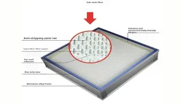
Figure 4: HEPA filter media structure and particle capture mechanism
Air Supply System: FFU, Air Diffusers & PAU
Fan Filter Units (FFUs) provide localized airflow control with typical power consumption of 150-300W per unit. For a 100m² ISO class 5 cleanroom, approximately 60-80 FFUs might be required, with total power consumption around 15-20 kW.
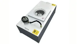
FFU ceiling layout pattern
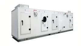
Packaged Air Handling Unit (PAU)
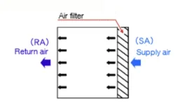
Return Air System & Airflow Balancing
Proper return air system design ensures uniform airflow patterns throughout the cleanroom. For a typical ISO Class 7 facility, return air grilles should cover approximately 20-30% of wall surface area to maintain proper air balance and prevent dead zones.
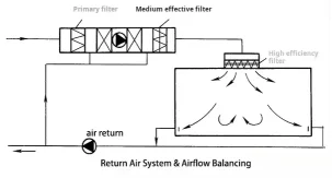
Figure 5: Complete airflow circulation path from supply to return
Pressure Differential Control: Cleanroom's "Protective Barrier"
Pressure differentials between adjacent areas prevent cross-contamination. Typical cascading pressure differentials maintain 10-15 Pa between ISO classes, with higher pressure (20-30 Pa) for containment areas handling hazardous materials.
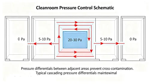
Figure 6: Pressure differential cascade between cleanroom zones
Impact of Temperature and Humidity Control on Airflow
Temperature stability within ±1°C and humidity control within ±5% RH are critical for maintaining consistent airflow characteristics. A 5°C temperature change can alter air density by approximately 2%, affecting airflow volumes and pressure relationships.
Cleanroom Airflow Design, Validation & Optimization
The systematic approach to Cleanroom airflow design begins with comprehensive requirements analysis and progresses through validation and ongoing optimization. This process ensures compliance with regulatory standards while maximizing operational efficiency.
Continuous improvement of Cleanroom airflow performance requires regular monitoring and data analysis to identify optimization opportunities. This approach maintains compliance while reducing operational costs over the facility lifecycle.
Design Phase: From Requirements to Solutions
Computational Fluid Dynamics (CFD) analysis enables virtual prototyping of airflow patterns before construction. A typical CFD analysis for a 500m² cleanroom might involve 5-10 million computational cells, requiring 24-48 hours of processing time on high-performance workstations.
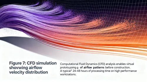
Figure 7: CFD simulation showing airflow velocity distribution
Validation & Testing: Ensuring Cleanness Compliance
Cleanroom validation follows a structured approach including Installation Qualification (IQ), Operational Qualification (OQ), and Performance Qualification (PQ). Key airflow parameters must be verified with calibrated instruments meeting ISO 17025 requirements.
| Test Parameter | Method | Instrument | Acceptance Criteria |
|---|---|---|---|
| Airflow Velocity | iso 14644-3 | Thermal Anemometer | 0.45 m/s ±20% |
| Air Change Rate | Volume Balance | Flow Hood | ≥ Design ACH |
| Particle Count | ISO 14644-1 | Laser Particle Counter | Per ISO Class |
| Pressure Differential | Digital Manometer | Micro-manometer | ≥10 Pa between zones |
Optimization & Continuous Maintenance: Maintaining High Efficiency
Regular maintenance schedules should include HEPA filter replacement every 3-5 years, with pre-filter changes every 3-6 months. Energy optimization strategies like variable frequency drives (VFDs) can reduce fan energy consumption by 30-50% through speed control based on actual demand.
| Maintenance Activity | Frequency | Tools/Instruments | Acceptance Criteria |
|---|---|---|---|
| Filter Integrity Test | Annually | Aerosol Photometer | ≤0.01% leak |
| Velocity Uniformity | Semi-annually | Anemometer | ±20% of average |
| Particle Counting | Quarterly | Particle Counter | Within ISO Class |
| Pressure Monitoring | Continuous | Pressure Sensors | Alarm at ±2 Pa deviation |
Industry Standards & Compliance Requirements
The ISO 14644 series provides the international framework for cleanroom classification and monitoring. Part 1 defines particle concentration limits, while Part 3 specifies testing methodologies for verifying compliance.
For pharmaceutical applications, EU GMP Annex 1 and FDA guidance documents impose additional requirements for airflow visualization studies and continuous monitoring of critical parameters in aseptic processing areas.
Key Standards Overview
- ISO 14644-1: Classification of air cleanliness by particle concentration
- ISO 14644-2: Specifications for testing and monitoring
- ISO 14644-3: Test methods for cleanrooms
- iso 14644-4: Design, construction and start-up
- EU GMP Annex 1: Manufacture of sterile medicinal products
- FDA Guidance for Industry: Sterile drug products produced by aseptic processing
Frequently Asked Questions
Q: Is cleanroom airflow direction important?
A: Absolutely. Airflow direction determines how contaminants are transported away from critical areas. In unidirectional flow systems, parallel streamlines prevent cross-contamination, while in non-unidirectional systems, proper airflow patterns ensure adequate mixing and dilution.
Q: How is cleanroom airflow velocity determined?
A: Airflow velocity is determined by the cleanroom classification and application. For ISO Class 5 unidirectional flow cleanrooms, the standard specifies 0.45 m/s ±20%. Lower classifications use air change rates instead of specific velocity requirements.
Q: What's the difference between FFU and PAU?
A: FFUs (Fan Filter Units) are individual units that combine a fan and HEPA filter for localized airflow control. PAUs (Packaged Air Handling Units) are central systems that condition and distribute air to multiple areas. FFUs offer flexibility, while PAUs provide centralized control.
Q: Does temperature and humidity affect airflow in cleanrooms?
A: Yes, temperature and humidity affect air density and viscosity, which influence airflow characteristics. A 5°C temperature change can alter airflow volumes by approximately 2%. Consistent environmental conditions are essential for maintaining stable airflow patterns.
Q: How often should cleanroom airflow be tested?
A: ISO 14644-2 recommends testing at maximum time intervals of 12 months for particle counts, 6 months for airflow velocity/volume, and 12 months for filter integrity. More frequent testing may be required based on risk assessment and regulatory requirements.
Conclusion: Building Efficient and Safe Clean Environments
Effective cleanroom airflow management represents a critical balance between contamination control, energy efficiency, and operational practicality. The principles outlined in this guide provide a foundation for designing, validating, and maintaining optimized cleanroom environments.
As technology advances, we anticipate increased integration of IoT sensors, machine learning algorithms, and predictive maintenance strategies to further optimize cleanroom airflow performance. These innovations will enable real-time adjustment of airflow parameters based on actual process requirements, reducing energy consumption while maintaining compliance.
For professional consultation on your specific cleanroom requirements, contact Deiiang™ experts. Our team, including product designer Jason.peng, brings decades of experience in designing and optimizing cleanroom environments across multiple industries.
© 2023 Deiiang™ Cleanroom Technologies. All rights reserved. | Product Designer: Jason.peng
This technical guide is provided for informational purposes only. Specific cleanroom designs should be developed by qualified professionals based on project requirements.