+86 13638632902
 Jason@cleanroomequips.com


 MENU
MENU
How can a high-performance cleanroom be implemented where space is constrained? Many industries encounter this situation. Standard cleanroom layouts generally require larger ceiling plenums, intricate ductwork, and wider service corridors. This all reduces the usable production area of the manufacturing floor.
A compact cleanroom should, ideally, occupy less space while not being less efficient. Smaller cleanrooms also do not indicate lower standards or less performance for cleanliness. This helps to eliminate the wasted volume, while sustaining the cleanliness of the environment and making it easier to maintain and operate it.
Well integrated and planned space-saving cleanroom design integrates ffu modules with ceiling systems, return-air paths, and personnel and material flow paths from the beginning. When done correctly, a compact layout can improve production output per area and reduce the operating costs for the cleanroom.
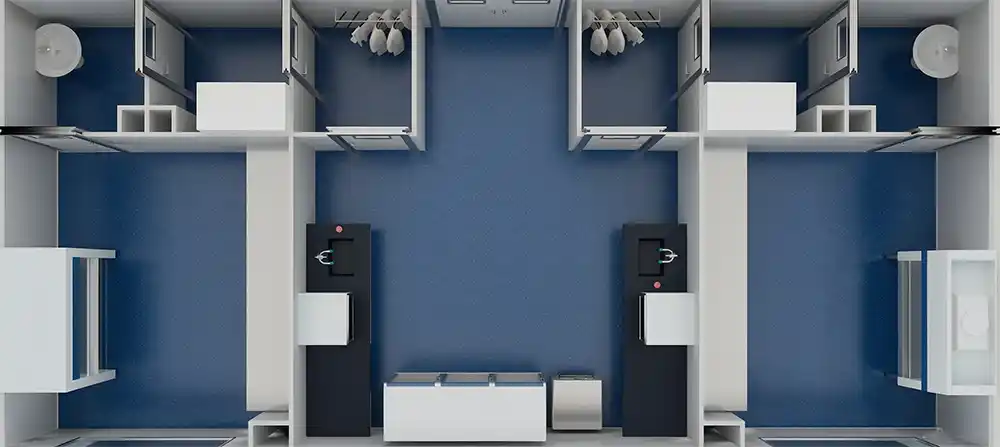
What Is a Space-Saving Cleanroom Design?
Core Meaning of Space-Saving Cleanroom Design
Essentially, space-saving cleanroom design means more than just compacting the cleanroom layout. The layout can be compact while still retaining the following:
- Obtain the required cleanliness level (iso 5, ISO 7, iso 8, etc.)
- Allow personnel and material flow paths to be unobstructed
- Provide adequate air exchange and effective airflow patterns
- Allow maintenance access for FFUs, filters, and electronics
- Prevent airflow interference between process equipment and workstations
- Comply with fire and safety codes, lighting, HVAC, and local regulations
The following three concepts are critical to space-saving cleanroom design, but are often confused:
- Reducing total floor area (suitable for small-scale production or limited budgets)
- Improving space utilization (changing arrangement of benches and equipment to maximize effective working area)
Minimizing non-productive space (reducing excess corridors, oversized buffer zones, and unnecessary plenum voids) without affecting safety for gowning, material transfer, or maintenance.
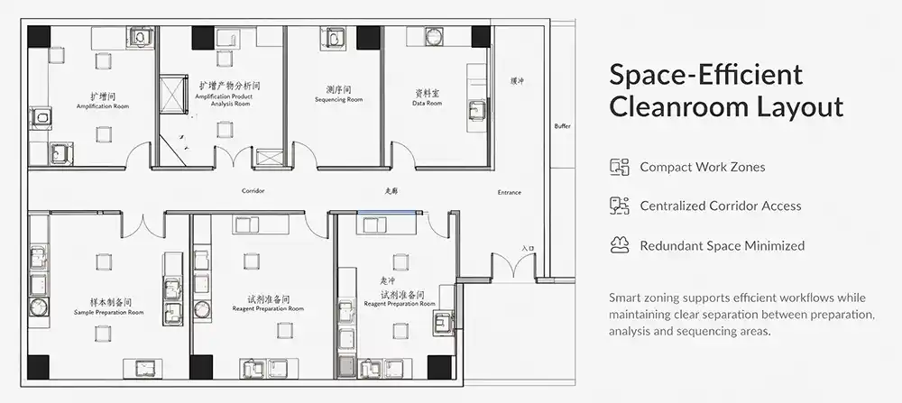
Why Is Demand for Small Cleanrooms Increasing?
- Before a large investment, most startups and R&D teams prefer small, pilot, or trial production cleanrooms.
- Many existing factories face retrofit restrictions due to column spacing and available ceiling height.
- Medical device manufacturers require the quick development of localized clean production spaces.
- Assembly lines for electronics require even higher levels of cleanliness for components.
- One-time large constructions are being phased out in favor of modular expansions.
- With energy and rental prices increasing, companies are forced to do the most with each square meter.
Which Projects Are Best Suited for Compact Solutions?
- Small-scale R&D laboratories
- Electronic component assembly areas
- Medical device production units
- Optical inspection and testing areas
- Aseptic filling and pre-treatment areas
- Clean weighing and sampling rooms
- Localized high-cleanliness workstations
- Clean production cells embedded in existing factories.
The Main Space Constraints in Small Cleanroom Projects
Inadequate Space for Equipment, Personnel, and Logistics
- Equipment situated within main areas of operation
- Overlapping paths for personnel and materials
- Doors swing into areas where equipment must be placed
- Limited access to workstations which are adjacent to walls
- Insufficient service space for maintenance personnel
- A material staging area encroaches on the clean production area.
Typical vs. Optimized Layout
A cleanroom with a poor layout of 50 m² may have only 28 m² of available production space. An optimized layout can yield a work area of 38 m², a gain of 36%.
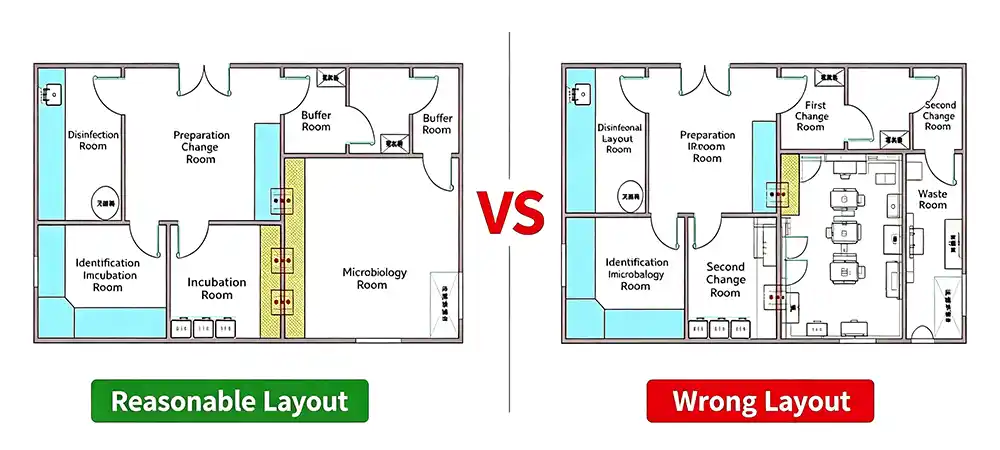
Insufficient Ceiling Height: Difficulty Arranging Ceilings, FFUs, and Return Air Plenums
- A cleanroom ceiling system occupies usable space.
- The thickness of an FFU decreases the available space in the ceiling plenum.
- The cleanroom design must integrate the supply air, return air, and lighting.
- Fire sprinklers and cable trays may limit the FFU placement.
- Insufficient ceiling heights can greatly affect the comfort of the operator and the installation of equipment.
For low ceiling cleanrooms, the FFU, ceiling module, and how return air will be managed need to be decided before construction starts. Compact FFU solutions are therefore critical.
Retrofitting Existing Factories: Fixed Column Grids and Pipelines
- The space is divided by structural columns.
- Existing HVAC systems are immovable.
- The floor load capacity is assumed to be inadequate.
- Wall and door openings are fixed.
- The available electrical capacity may be inadequate to meet the needs.
- Production cannot be halted for long periods.
How to Plan a Small Cleanroom Layout
Step 1: Divide Functional Zones Based on Process Flow
- Personnel entry and gowning area
- Material entry or pass-through window
- Buffer zone (airlock / change room)
- Core clean production zone
- Inspection or packaging area
- Waste collection and transfer zone
- Equipment service and utility zone
Step 2: Design Personnel and Material Flow Paths
Flow of personnel: Gown → Hand wash/air shower → Buffer → Production → Exit
Flow of materials: Receiving Raw Materials → Outer Packaging Removal → Cleaning/Disinfection → Pass-through → Production Use → Finished Goods Output
Personnel flow and material flow paths must not cross. Pass-through points must be located as close as possible to the point of use.
Step 3: Reserve Minimum Maintenance Space
- Space requirements for FFU access for motor and filter replacement
- Clearance space for the electrical panel and control box
- Space requirements for the removal of lighting and ceiling tiles
- Space for airflow and differential pressure testing
- Space for move-in/move-out of equipment
- Clearance space for future wall and door installations
Compacted FFU Solutions for Limited Spaces
What's an FFU?
FFU stands for fan filter unit. It is a box that draws in air from an upper region, filters it through a HEPA or ULPA filter, and then dispenses it downwards. Because of their modularity, a number of Fan Filter Units can be placed in a grid-like fashion in ceiling tiles.
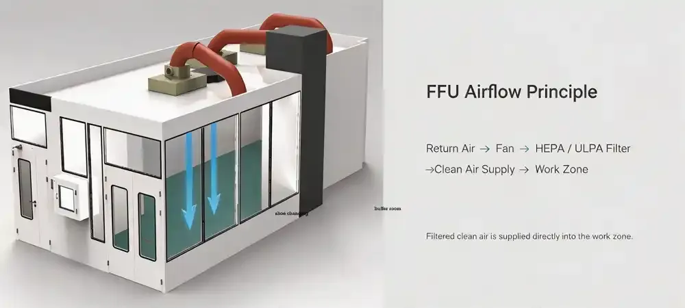
Why Are FFUs Great for Compact Cleanrooms?
- No extensive and bulky supply air ductwork is needed.
- Can be designed in a number of different ways to fit through a variety of room shapes.
- FFUs can be designed to fit enough compact space for clean zones.
- Can be designed to allow easy staged expansion.
- Allows an easy installation in low ceiling spaces.
How to avoid airflow short-circuiting in Low Ceilings
When the vertical distance in a space becomes less than 2.6 m, the possibility low ceiling short-circuiting becomes a significant concern. It is possible that supply air is pulled directly through return air grilles without providing sufficient airflow through the workspace. This is why Deiiang™ uses a combination of perforated raised floors and low wall return air chases that work to control the face velocities of these return air chases in the range of 1.5–2.0 m/s to ensure that airflow is directed vertically from the surface of the raised floor to the work surface.
🔴 Traditional (high short-circuit risk)
Supply air → immediate return through floor grilles → bypasses work area.
✅ Optimized with side-wall return chase
Supply air → sweeps work zone → exits through low-wall slots → prevents short-circuiting.
What Matters in Compact FFU Design?
Deiiang™ FFU systems are designed by Jason.peng and have dimensions that are compatible with standard ceiling grids. They have rated airflow between 1000 to 2000 CMH and have adjustable speed with EC motors. They also offer H14 or U15 filters.
How to calculate the number of required FFUs?
Use the following steps: define area, choose target ISO, analyze the loads, determine required air changes for the defined area, assign FFUs to the area, and check that those FFUs will fulfill the defined area requirements.
💡 Quick Tool: cleanroom ffu Estimator
Reference: Cleanliness Class, Air Change Rate & FFU Coverage
| ISO Class (14644-1) | air changes per hour (ACH) | FFU Ceiling Coverage | Typical Air Speed (m/s) |
|---|---|---|---|
| ISO 5 (Class 100) | 240 – 480 | 60% – 80% | 0.35 – 0.45 |
| ISO 6 (Class 1,000) | 150 – 240 | 35% – 50% | 0.25 – 0.35 |
| ISO 7 (Class 10,000) | 60 – 90 | 15% – 25% | 0.15 – 0.25 |
| ISO 8 (Class 100,000) | 20 – 45 | 5% – 15% | 0.05 – 0.15 |
Reference: Cleanliness Class, ACH & Coverage
| ISO Class | ACH | Coverage |
|---|---|---|
| ISO 5 | 240–480 | 60–80% |
| ISO 6 | 150–240 | 35–50% |
| ISO 7 | 60–90 | 15–25% |
| ISO 8 | 20–45 | 5–15% |
Typical air speed: ISO5 0.35–0.45, ISO6 0.25–0.35, ISO7 0.15–0.25, ISO8 0.05–0.15 m/s.
Traditional and Compact FFU Layouts
Basic Differences
In traditional design, a centralized air supply system means long runs of ductwork and a large air handling unit (AHU). For small or retrofit projects, this poses challenges as ductwork takes up plenum space, increases project duration and reduces flexibility.
Supply by modular fan filter units (FFUs) employs many smaller, discrete units. While modular supply is more flexible and easier to scale, care must be taken for noise, electrical zoning, filter changes, and general airflow management.
⚠️ Noise & Vibration Control with Compact FFU Arrays
In a small footprint containing 10–20 FFUs, background noise may be controlled and kept at levels below 65 dBA. Deiiang™ employs EC variable speed motors for groups of FFUs with RS485/Modbus, where reducing fan speed from standard to 15% yields a decrease in sound pressure level from 4 to 6 dBA, thus maintaining the cleanroom at levels less than 65 dBA.
Pros and Cons Comparison
Compact FFU Layout – Pros
- ✓ Flexible modular layout
- ✓ Suitable in limited or confined spaces
- ✓ Less ductwork
- ✓ Easy zoning
Potential Limitations
- ✕ Requires balancing airflow
- ✕ Requires tuning
- ✕ Must plan ahead for filter changes
- ✕ Requires noise control
- ✕ Requires electrical control
Five Space-Saving Strategies for Cleanroom Design
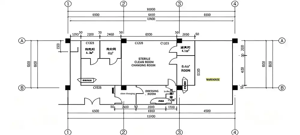
Strategy 1 — Use of Modular Ceiling and Wall Systems
- Use standard, interchangeable modular design
- Lower the amount of cutting with custom design
- Passive coordination with lighting, FFUs, and tiles
- Use modular design to allow for easy access
- Put standard interfaces for future expansion
Strategy 2 — Separate Cleanroom Levels by Process
- Material staging: ISO 8
- Core assembly: ISO 5
- Inspection: ISO 7
- Gowning: gradient
Avoid lowering the cleanliness level of a critical process zone to mitigate costs.
Strategy 3 — Careful Use of Vertical Space
- Integrate utilities into the plenum
- Relocate storage away from the core
- Maximize ceiling height
- Reduce redundant ductwork
- Confirm the location of sprinklers and cable trays ahead of time
Strategy 4 — Inclusive Workspace Design
- Work surface
- Local clean air supply
- Lighting for tasks
- Storage for tools
- Inventory
- Data collection
Strategy 5 — Planning for Adaptability to Workspace Mobility
- Setting aside FFU spaces
- Electrical circuits
- Channels for control
- Pathways for moving walls
- Pass through windows
Deiiang Project: Developing Compact Cleanroom in a Space-Constrained Location
Project Summary
- Location: Southeast Asia location in the Electrical Manufacturing Hub
- Industry: Precision electronics assembly
- Cleanroom area: 85 m²
- Clear height: 2.8 m
- Target cleanliness: ISO 7 with localized ISO 5
- Project duration: 6 weeks
- Deiiang™ scope: Design of FFU and supply, ceilings, installation, test and validate
Important Challenges and How We Overcame Them
Challenge 1: Boundaries Due to Layout – Rearranged layout to support flow of tasks.
Challenge 2: Ceiling Height – Low profile plenum with compact FFU solutions.
Challenge 3: Existing MEP – FFUs strategically placed to avoid fixed obstacles.
Challenge 4: Zero Downtime – Multiple phases of installation.
Challenge 5: Space for Future Growth – Reserved extra FFU and electrical capacity.
Results
- Production area increased from 42 m² to 58 m² (38% gain)
- ISO 7 compliance with 8 new workstations (vs 5 originally) and ISO 5 at the inspection station.
- Pressure differentials of 15–20 Pa
- 2.8 kW Energy consumption per 10 m²
Data from the Deiiang™ project actual commissioning record. Results may vary.
What is the cost of a Compact Cleanroom Project?
Key factors
- Cleanroom size, target ISO grade, cleanroom ceiling height, panel materials, FFU number and grades, filter grades, degree of complexity of the cleanroom HVAC system, electrical systems, and cleanroom fit-out, number of air locks, and air showers, gowning rooms, and the difficulty of installation based on cleanroom location and the testing requirements of the cleanroom.
CapEx vs. OpEx
CapEx: Cost of designing the cleanroom, creating the cleanroom shell and ceiling, FFUs, filters, electrical work, and installation.
OpEx: Cost of operating the cleanroom which includes the cost of fan energy, filter replacements, and cleanroom maintenance, the cost of cleaning the cleanroom, and the testing of the cleanroom as well as the cost of spare parts.
Cost of the cleanroom does not always determine the total cost of ownership of the cleanroom.
Cleanroom Design, Installation and Delivery Process
Phase 1-6
- 1. Requirement Collection: Product type, ISO grade, physical dimensions, weight/load, future considerations.
- 2. Site Survey: Actual dimensions of the room and HVAC, electrical, fire systems and how access.
- 3. Solution Design: Layout design, FFUs, airflow and controls, and a BOM.
- 4. Manufacturing & Prefab: Modular systems reduce cutting on site.
- 5. On-Site Installation: Cleanroom walls, followed by the ceiling, FFUs, doors, electrical work and sealing.
- 6. Commissioning & Validation: airflow, air velocity, pressure, particles, smoke, and integrity of
🔬 Critical detail: DOP/PAO aerosol injection ports (upstream of HEPA filters) must be pre-installed. Deiiang™ includes standard upstream test ports in all modular ceilings, enabling hassle-free filter integrity testing.
Things to Consider When Purchasing a Compact Cleanroom Solution
It's Not Enough to Compare Cleanroom Equipment Costs
- What is the cleanroom vendor's performance history?
- Completed engineering design?
- Does it come with an installation?
- What about commissioning and validation?
- Are as-built drawings included?
- Does the price include worker training?
- Are replacement filters easy to get?
- What is the lead time for spare parts?
- Does the vendor offer online technical assistance?
- What does the warranty cover?
Buyer's Guide Section Ten: Checklist (Interactive)
Common Errors in Designing Small Cleanroom Layouts
Designing sedate even FFU distribution by area
Create dead flows (e.g. no FFU flow) which causes contamination.
Ignoring the integrated arrangement of FFU, equipment, and lighting
Results in on-site clashes, module strain, and maintenance issues.
Overcompressing aisles and limiting general maintenance
Causes discomfort to the user, makes equipment movement a safety hazard.
Focusing more on the initial investment of the build
Long term costs on energy and filters or costly rework.
Skipping the last validation step
Final validation cannot be done on look and promise.
Space Utilization Comparison
Traditional Layout
Compact Layout
Project Flow Chart
Lightweight Scorecard
Frequently Asked Questions
Can a cleanroom be built in a low-ceiling facility?
Yes. By implementing ultra-slim EC-FFUs (215mm profile) and lateral return air chases, Deiiang™ has successfully commissioned iso 7 cleanrooms in facilities with structural ceiling heights as low as 2.7 meters.
Is a compact FFU solution suitable for iso 5 cleanrooms?
It can be, but not by FFU type alone. ISO 5 compliance requires proper filter selection, airflow organization, air change rate, layout, and validation testing. Localized ISO 5 zones are often more practical.
How many FFUs does a small cleanroom need?
Depends on area, ceiling height, ISO grade, personnel, equipment load. Use the interactive calculator above for a quick estimate, but final design requires engineering validation.
How long does a compact cleanroom project take?
Typically 5–8 weeks: design 1–2 weeks, manufacturing 2–3 weeks, installation 1–2 weeks, validation 3–5 days.
What maintenance is required for FFU systems?
Fan checks, noise/vibration monitoring, airflow measurement, filter replacement based on pressure drop, periodic cleaning, and documented records.
References
- ISO 14644-1:2015 – Cleanrooms and associated controlled environments
- ASHRAE Handbook – HVAC Applications, Clean Spaces
- IEST-RP-CC012 – Cleanroom Ceiling Systems
- EU GMP Annex 1 – Manufacture of Sterile Medicinal Products
Plan Your Compact Cleanroom with Deiiang™
Have a low-ceiling facility or limited production area? Send Deiiang™ your floor plan, room dimensions, and required cleanliness level. Our engineering team can help evaluate the layout, FFU quantity, airflow strategy, and project delivery requirements.
© 2026 Deiiang™ – Smart Clean Environment & Green Energy Systems