+86 13638632902
 Jason@cleanroomequips.com


 MENU
MENU
iso 5 airborne particle control is not ESD safe.
HEPA/ULPA filters cannot replace grounding, equipotential bonding, conductive flooring, or ionization, even though they cut airborne particles. It is crucial to merge the use of high cleanliness, low-outgassing materials, and stable airflow together with the prevention of static discharges from the onset.
ESD Risks in an iso 5 Microelectronics cleanroom
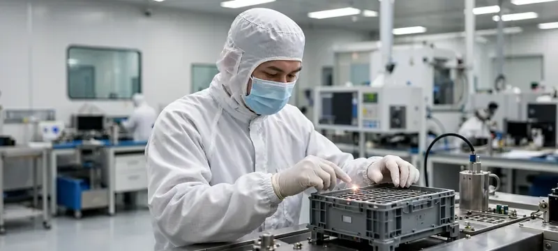
Although an ISO 5 rating provides superior control of particles, the resulting environment of dry air, high velocities, and a high frequency of interactions with materials can lead to an excessive build up of static charge on cleanroom materials. Again, a cleanroom designed without static control features leaves a persistent hidden threat of ESD to all sensitive equipment.
Where static charge is generated
Multiple daily operations can lead to a build up of static.
- Personnel movement: cleanroom garments and shoes creating friction with the floor.
- Material handling: insulating wafer carriers, trays, films, and packing.
- Automation: fast moving parts on conveyor belts, robotic arms, and rollers.
- Manual tasks: operators physically touching the equipment, workstation or product.
- Environmental factors: dry air, high local air velocities, and a separation of materials.
- Unintended conductors: ungrounded equipment, isolated metal, fixtures, and makeshift tools.
The risk grows when static discharge prevention measures are not incorporated into the design at the beginning.
What can be damaged
ESD events can lead to immediate failures, latent defects, and operational disruptions:
- Device damage: catastrophic failures (for example, oxide breakdown or junction melt) or latent failures that lead to an increased likelihood of failure.
- Process contamination: charged surfaces attract submicron particles. This leads to increased local contamination and reduced yield.
- Production disturbances: false alarms, resets to equipment, scrapping of products, and loss of yield.
An ESD event is often unnoticed until the final test. Therefore, prevention is far more effective in terms of cost than dealing with the works after.
Risk of CDM vs HBM: CDM is the larger risk in an automated iso5 environment
In microelectronics clean rooms, the primary threat to safety and exploding the CDM is much more of a threat than the HBM. In this environment, automated handlers, robotics arms, and conveyor belts discharging after being charged can occur within an even much smaller timeframe than 1 nanosecond.
For CDM, discharge is higher than 15 A with rise times in the 200–300 picoseconds, meaning a localized heating occurs from a breakdown of the dielectric and HBM cannot do this with a lower current and a slower rise time. Separating CDM sensitivity is the most critical ESD design requirement.
| Parameter | HBM | CDM |
|---|---|---|
| Peak Current | 1.3 A (at 2 kV) | > 15 A (at 1 kV) |
| Rise Time | 2–10 ns | < 0.5 ns |
| Discharge Energy | microjoules | millijoules |
| Typical Sensitivity | 100–2000 V | 50–500 V |
| Primary Source | Personnel | Automation/Materials |
For CDM-sensitive design: ESD flooring for ISO 5 with point-to-point resistance < 1×10⁹ Ω, grounding all conductive automation, and the placement of overhead pulsed DC ionization directly over exposure areas is required. HBM controls (wrist straps and heel grounders) are insufficient.
Risk is not uniform across process zones
An iso 5 cleanroom does not house areas with the same risk of ESD. Risks evaluated on a zone-based system require the following controls:
| Zone | Risk | Controls |
|---|---|---|
| Wafer exposure / lithography | High | Conductive material flooring, ionizers, grounded workstations |
| Die bonding / packaging | High | ESD flooring, grounded Tools, Wrist straps |
| PCB / component assembly | High | An EPA with full ESD controls |
| Test & rework | Medium | Grounded mats, ionization, with verification periodic |
| Material transfer / staging | Low–Med | Conductive ionization carts and grounded racking |
An ESD risk heat map across the facility assists in determining prioritization of ionizers and ESD flooring for ISO 5.
Standards and Design Criteria

When designing a cleanroom for ESD protection, the designer should understand the applicable standards to ensure the cleanroom is designed for high quality performance.
Standards for the design team to coordinate
Check the most recent versions of these foundational documents:
- ISO 14644 — cleanroom monitoring, classification, and related controls.
- ANSI/ESD S20.20 — Protecting electrical and electronic components — ESD control program requirements.
- IEC 61340-5-1 — Electrostatic protection of electric components.
- ANSI/ESD STM7.1 — Resistance of flooring materials — Point-to-point and ground resistance.
- ANSI/ESD STM97.1 / 97.2 — Testing of the shoe–floor–person system.
- ANSI/ESD SP3.3 — Periodic audit of ionizer effectiveness.
- SEMI standards — ESD specific requirements as applicable.
Always check the year and scope when citing; previously established standards might incorporate outdated practices.
Establish the ESD control plan before selecting materials
The ESD Control Plan describes all the requirements pertaining to the control of static, guiding the selection of materials, layout, and verification. Use the following inputs:
- Device sensitivity levels (HBM, CDM, etc.)
- Personnel and material flow
- Floor–shoe combination
- Grounding of workstations and equipment
- Inventory of insulating materials
- Acceptable humidity
- Need for ionization
- Testing, limits, and frequency
- Out of specification corrective actions
An ESD Control Plan allows clear criteria for the specification of ESD flooring for ISO 5, ionizers, and grounding.
Use project-specific limits
The limits for floor resistance, grounding personnel, and ion balance are determined by the project ESD Control Plan, device sensitivity, relevant standards, and customer requirements. Never use a single value of 'resistance'.
| Control Parameter | Project Target | Test Method | Deiiang™ Verified Value | Evidence |
|---|---|---|---|---|
| Floor point-to-point resistance | Per project spec | ANSI/ESD STM7.1 | 1.0 × 10⁵ to 1.0 × 10⁹ Ω | Report on file |
| Floor-to-ground resistance | Per project spec | ANSI/ESD STM7.1 | < 1.0 × 10⁹ Ω | Report on file |
| Personnel–shoe–floor system | Per ESD plan | ANSI/ESD STM97.1 | Measured on site | Acceptance record |
| Ion balance | Per device sensitivity | ANSI/ESD SP3.3 | ±15 V, typical | Calibration record |
| Charge decay time | Per project target | IEC 61340-5-1 | < 2 seconds | Report |
Selecting ESD Flooring for an iso 5 cleanroom
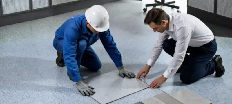
When designing an antistatic cleanroom design, choosing the correct flooring option is one of the most important decisions that needs to be made. ESD flooring builds the foundation of a cleanroom's ESD control system and needs to be reliable throughout the entire lifespan of the cleanroom.
The floor is a system, not only a surface material
When looking at a complete system of ESD control flooring, it needs to cover components such as:
- An ESD surface layer that is conductive or static dissipative
- Conductive layer or bonding layer
- Copper foil or grounding grids
- Grounding point connections
- Equipotential bonding
- Shoes or heel grounders
- Test points and a maintenance plan
All of these components need to be fully specified, correctly installed, and validated for a system.
Flooring options
Here are the common types of ESD flooring for ISO 5:
- Conductive PVC (homogeneous sheet) – consistent electrical performance and compatible with cleanrooms.
- Static-dissipative PVC – good for most EPA areas.
- ESD epoxy/polyurethane coating – seamless and resistant to chemicals.
- Conductive raised access flooring – perfect for service zones where equipment is housed.
- Metal or composite access flooring – high load capacity with embedded grounding.
| Criteria | Conductive PVC | Static-Dissipative PVC | ESD Epoxy Coating | Raised Access Floor |
|---|---|---|---|---|
| Electrical stability | Excellent | Good | Excellent | Good |
| Cleanroom compatibility | Excellent | Good | Good | Good |
| Chemical resistance | Moderate | Moderate | Excellent | Variable |
| Load capacity | Moderate | Moderate | High | Very high |
| Installation complexity | Moderate | Moderate | High | Moderate |
CapEx vs. OpEx decision matrix: Conductive PVC vs. ESD Epoxy
Looking at ESD flooring for ISO 5, the initial cost (CapEx) is only part of making the decision. The flooring's maintenance, cleaning, and longevity (OpEx) typically determine the accurate cost of ownership of the flooring.
Periodically requires conductive waxing but resists most cleanroom cleaners.
Seamless and very good chemical resistance. Reapplication is required every 3 to 5 years.
Provides flexible underfloor access with integrated grounding for a long period.
Suitable for lower risk zones, Static-Dissipative PVC is not recommended for use in the high CD risk zones.
Deiiang™ recommendation: For cleanrooms catering to microelectronics in ISO 5 with CDM-sensitive devices, PVC with conductance in the region of 1.0×10⁵–1.0×10⁶ Ω is the best option for an ideal balance among the factors of performance, cleanability, and lifecycle cost. Where aggressive solvents are in daily use, epoxy coatings are preferred.
Compatibility with ISO 5 cleanroom construction
The integration of flooring with the cleanroom shell impacts both the cleanliness and the ESD continuity:
- Coved profiles should be used for wall-to-floor transitions to eliminate corners that collect dust.
- Sealed joints and cleanroom panels with a tongue-and-groove design are beneficial in controlling leakage and pressure differentials.
- Floor-penetrating services, equipment bases, and door seals do not break the ESD grounding path.
- Flooring systems should be coordinated for deflection control, load-bearing, grounding continuity, and access for maintenance.
- All surface finishes, sealants, and adhesives must be tested for compatibility.
⚠️ Critical: chemical cleaning agent compatibility and cleaning protocols
Cleaning agents are responsible for ESDF (electrostatic dissipative flooring) failures in ISO 5 cleanrooms. ESD flooring for ISO 5 needs to be validated for the cleaning agents used in the facility.
Allowed (tested compatibility): 70% isopropyl alcohol (IPA) wipes, neutral detergents in very diluted concentrations, hydrogen peroxide-based disinfectants (e.g. Spor-Klenz).
Prohibited (destroys flooring): Phenolic compounds, high concentrations of bleACH, citrus-based cleaning agents, scraping pads.
Deiiang specification block
Deiiang™ cleanroom system components provide the interface/storage for ESD flooring systems. The following information describes the cleanroom shell and must be validated against the official documentation/testing for the systems in question.
- Effective width of Cleanroom Panels is approximately 1150 mm with thicknesses between 50 and 100 mm; panels are hand made and width ranges between 150 mm and 1180 mm.
- T-grid ceiling systems are available in 1200 x 600 mm, 1200 x 1200 mm, or custom sizes.
- Blank and T-grid panel load performance: at a uniform load of 4000 N, approx. 0.84 to 0.97 mm with residual deformation of approx. 0.05 to 0.08 mm (model dependent, to be confirmed with official test report).
Note on structural integrity of Deiiang™ systems: the extremely low deflections (0.84 – 0.97 mm at a 4000 N point load) of T-grid systems allows copper grounding raised floor tapes and ceiling bonding grids to cross continuous gaps without loss of grounding, thus preventing contact fatigue over the life of the facility.
Note: these values provide information about cleanroom structural components and are not ESD flooring electrical performance values.
Flooring Acceptance Checklist
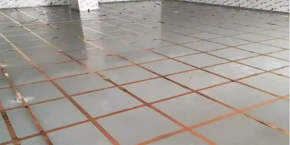
ESD flooring system: conductive layer, copper grid, and ground connection. (Deiiang™ installation reference)
Interactive Tool: ISO 5 ESD Coverage Estimator
Select your critical device sensitivity (CDM Volts) to get baseline recommendations for ESD flooring for ISO 5 and ionizer density.
* Baseline recommendation based on ANSI/ESD S20.20 and Deiiang™ field data. Final design must be verified on site.
Grounding and Equipotential Bonding
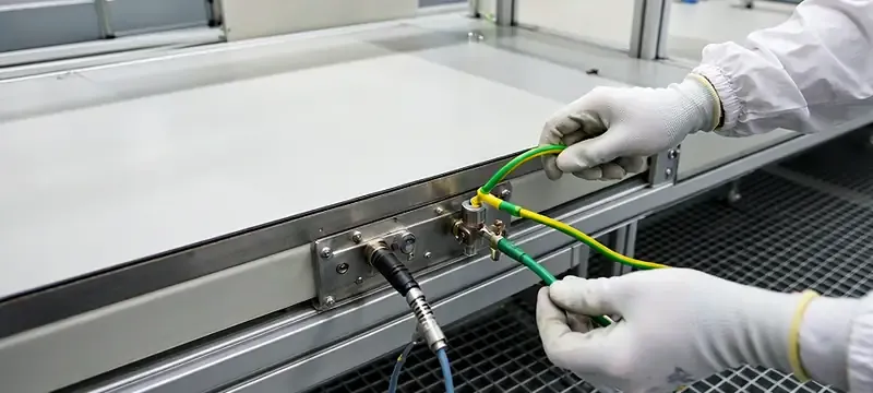
Without copper bonding, grounding, and equipotential bonding, ESD flooring and ionizers do not perform as intended. Create a coordinated grounding architecture within your organization.
Differentiate these grounding functions:
- Protective earth (PE): safety grounding for equipment.
- ESD technical ground: dedicated common point ground for ESD control.
- Chassis grounding: connects equipment frames to the ESD ground.
- Workstation grounding: connects wrist straps, mats, and tools.
- Floor grounding: connects the ESD floor system to the common ground point.
- Personnel grounding: via shoes, heel grounders, or wrist straps.
- Equipotential bonding: connecting isolated conductive parts to maintain equal potential.
A single 'earth rod' is rarely sufficient; the system must be designed holistically.
⚠️ Critical: Avoid "false grounding" — separate ESD ground from PE
In microelectronics facilities, you should not mix ESD technical ground with protective earth (PE). Leakage currents and harmonic interference from power equipment can couple into the ESD ground and damage sensitive devices. Deiiang™ suggests a dedicated common point ground (CPG) with a facility ground resistance of less than 1 ohm and is separate from the grounding conductors of the power circuitry.
Grounding points that are often overlooked
Keep in mind these often-overlooked items:
- Cleanroom work tables
- Shelving and carts
- Equipment pedestals
- Temporary floor panels
- Door frames, pass-throughs, and metal partitions
- Temporary maintenance tools and test equipment
- Pipe supports and all metallic structures beyond the ground
Common point grounding scheme
A common point grounding scheme shows the hierarchy of grounding from
- Personnel → shoes → ESD floor → floor grounding grid → common ground point
- Equipment / workstations / carts → equipotential bonding → common ground point
This layout dictates that the cleanroom design incorporates all elements of the grounding scheme to provide a common reference potential.
Ionizer Placement Without Disrupting ISO 5 Airflow
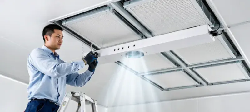
Ionization solves the issue of static charge on insulators that are on surfaces that are not grounded and remain insulated. Careful ionizer placement must be done to not disrupt the unidirectional airflow of the cleanroom.
Where Ionization is needed
If insulating materials remain and cannot be removed, then ionization is required. This includes areas like:
- Handling stations for exposed wafers or devices
- Locations where plastic trays, carriers, and films are used
- Conveyor, sorting, and packaging stations
- Load/unload ports of equipment
- Rework and microscope workstations
- Local risk areas of insulators found in automated equipment
Ionization adds to and does not substitute for grounding and conductive flooring.
Placement rules
For the most appropriate placement of ionizers, the following rules must be considered:
- Airflow should be directed to the surface of concern and not to the operator.
- Ionizers placed where the airflow is directed to a return grille will be ineffective.
- Obstructions to unidirectional airflow of HEPA/ULPA will render the placement of an ionizer ineffective.
- Identify the cause of a shadow in an area of concern.
- Determine the number of required ionizers using the ion balance and decay time tests, not an area of the room.
- Check again after eACH relocation of equipment and every process change.
Ionizer positioned above work surface, aligned with ffu airflow
The ionizer is placed above the workplane, directing ions downward in the same direction as the ffu unidirectional flow. No obstruction, no turbulence, and full coverage of the charged target area. Ion balance verified at working height.
Ionizer aimed at operator, blocked by equipment, near return air
The ionizer is placed at an angle, with airflow crossing the FFU stream, creating turbulence and shadow zones. Ions are drawn into the return grille before reaching the work surface, reducing effectiveness and potentially disturbing particle control.
Coordination with FFUs and HEPA/ULPA filters
Deiiang™ FFUs and filters are designed for ISO 5 performance:
- FFU operation: air is drawn from above, passes through HEPA filter, delivers uniform downward airflow at 0.45 m/s ±20%.
- HEPA filters (H13/H14): efficiency of 99.97% to 99.99% at 0.3 μm (H13) and 99.995% to 99.999% at 0.3 μm (H14).
- ULPA filters (U15–U17): efficiency at 99.99999% to 99.999995% at 0.12 μm (U17).
To protect particle control, the location of each ionizer, along with the control flow unit (CFU) the ionizer's velocity, thermal plumes from the ionizer, air return paths, and working plane height must be validated.
⚠️ With corona ionizers, ozone is produced and particles are emitted.
High voltage corona ionizers can produce ozone [O₃] and charged particles from electrode wear, both of which degrade wafer yield in clean iso class 5 environments. Deiiang™ recommends pulsed-DC ionizers with quartz or titanium emitter pins and active feedback control to maintain ion balance and minimize ozone (to less than 0.005 ppm at a distance of 30 cm). Avoid tungsten needles and continuous-DC designs for sensitive lithographic areas.
Improving the efficiency of CFD and field verification requires the following workflow:
- Layout modeling and obstruction identification
- CFD airflow analysis
- Preliminary installation
- Working plane measurements
- Angle and distance adjustment
- Retesting and documentation.
Field verification with a charged plate monitor provides direct evidence of ionizer effectiveness.
Humidity: Supporting Measure, Not the Primary ESD Control
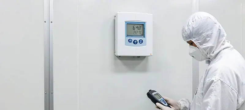
Humidity can increase ambient moisture and improve the charge dissipation of the substrate. But it does not provide a substitute for the grounding, personnel grounding, specific flooring, grounded ionization control, and managed transport of materials.
Here's what Deiiang™ Variable Frequency Air Handling Units offer:
- Temperature Control: Settable between 8 and 45°
- Humidity Control: Settable between 35% and 90%
- Constant temp and humidity controls allow for cooling in the range 20 to 26° with an accuracy of ±1° and heating in the range 20 to 26° with accuracy of ±2°.
- Humidification: Electrode humidifier: 6 kg/h - 110 kg/h
- Data logging capabilities include 14 day time stamped humidity and temperature logs, fault logs, and 10 years of operation logs.
Important! The aforementioned ranges are the performance capabilities of the equipment, and in most cases, these ranges do not correspond to the best practices for microelectronics. For the actual relative humidity setpoints, you should consider the sensitivity of the product, the corrosion risk, the material's tendency to absorb moisture, and the ESD (electrostatic discharge) sensitivity. Relative humidity can be considered a secondary effect; it should never be the primary measure for static discharge prevention.
Cleanroom Materials and Components That Affect ESD Performance
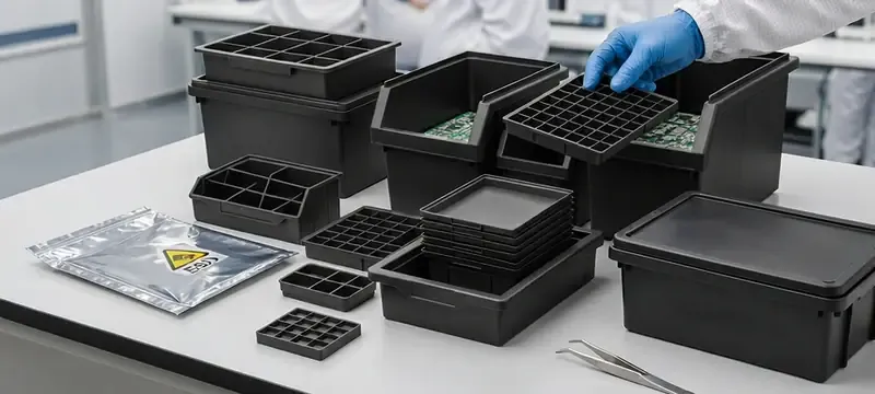
The cleanroom envelope can be affected by all components, materials, structural members, and filtration and airflow devices. ESD assessments must be completed on all of the listed components.
Wall and ceiling interfaces
The Deiiang™ panel systems provide a structural shell for a cleanroom.
- The 50 mm panels are continuous and interlocking, which helps to reduce air leakage and maintain differential pressure.
- Coved cleanroom corner aluminum profiles help avoid dust collection in dead zones.
- Ceiling suspension systems come with 1200 mm (typical) spacers and provide support to avoid panel sag.
- For support, wall panels come with pull rivets (about 300 mm) spacing to provide a 300 mm anchored floor track.
If structural components are conductive (e.g., aluminum profiles, steel framing), they should be evaluated for equipotential bonding to avoid creating isolated conductors.
Windows, doors and pass-throughs
Typical windows, doors and pass-throughs that comply with cleanroom standards include:
- Standard cleanroom doors with a leaf thickness of 50 mm.
- Airtight closures utilize rubber plastic sealing strips on 3 sides and a drop-down seal on the bottom.
- Observation windows contain double-layer tempered glass that is usually 5mm with a 20mm silkscreened border.
- Grounding continuity cannot be interrupted at thresholds, automatic door tracks, or material pass-throughs.
Filters and Airflow Equipment
FFUs, AHUs, and HEPA/ULPA filters lack ESD safety and should be evaluated for ESD compliance:
- Deiiang™ AirPioneer TAC airflow range: 1,000–60,000 m³/h
- AirPioneer TBC airflow range: 1,000–360,000 m³/h
- The Semiconductor MAU's airflow configurations range from 40,000–180,000 m³/h, with a recommended coil face velocity of 2.5 m/s or less.
- EC direct driven fans eliminate belts, and as a result, reduce the generation of wear particles.
Deiiang™ EC fans offer the advantage of direct-drive EC fans, which not only eliminate the generation of wear particles from belts, but also eliminate one of the major sources of static. Belt friction can generate in excess of 5,000 V of static. Through the use of direct-drive EC technology, Deiiang™ fans maintain a static discharge prevention approach at the air-handling level.
These data of air-handling systems are not substitutes for ESD measurements and ESD verification.
Installation and Commissioning Workflow
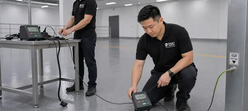
Systematic workflows allow for the correct installation of ESD flooring for ISO 5, grounding, and ionizers.
Commissioning Devices
Main devices during commissioning are:
- Surface Resistance Meter with Concentric Ring Probes
- Floor Resistance Testing Kit (with ASTM/ANSI electrodes)
- Personnel Shoe Floor Test System
- Electric Field Meter
- Charged Plate Monitor (CPM)
- Ground Continuity Tester
- Temperature and Humidity Data Logger
- Particle Counter according to iso 14644
- Anemometer and Airflow Velocity Meter
Deiiang™ Case Study: ISO 5 Microelectronics Cleanroom ESD Control
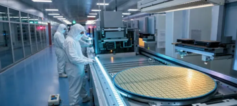
Deiiang™ has achieved integrated ESD and cleanroom systems for several projects in Microelectronics. The following case study is based on a validated project of a cleanroom of 3,200 m² in the Suzhou Integrated Circuit Industrial Park.
General overview of the project
- Location: Suzhou IC industrial park, China
- Industry: Semiconductors/advanced packaging
- cleanroom class: ISO 5 (verified by third party testing, report #iso5-2024-089)
- Area: 3,200 m² of the cleanroom
- Process: Wafer thinning, dicing and die bonding (CDM-sensitive)
- Scope of Deiiang™: Full package of ESD and Cleanroom - wall and ceiling panels, conductive PVC flooring, FFUs, AHUs, pulsed-DC ionizers, grounding topology, installation, and commissioning.
Project Challenges
- The interaction of ISO 5 unidirectional 0.45 m/s airflow ±20% with overhead ionizers
- Disruption of bonding continuity with large-volume dicing/bonding machines
- CDM risk posed by plastic waffle trays and insulating dicing tapes
- Ionization shadow zones caused by a tight equipment arrangement
- Integration of ESD control at floor thresholds, raised floors and wall-floor junctions
- Humidity control at 42%–46% RH was a process requirement and could not be used for ESD control
Deiiang Solutions
- Created a zone-based ESD risk assessment for the 3200 m² ISO 5 area
- Conductive PVC flooring with sub 1x10⁶ Ω with a copper grid of 500 mm and 48 dedicated grounding points were designed
- Common point grounding (CPG) system was used with < 1 Ω resistance for all equipment, workstations and metal components
- Optimized the number of pulsed-DC ionizers at 64, using CFD and smoke tests with 1 ionizer for every 2.8 m² of critical work surface
- Validated and established ion balance (±12 V average) at all 72 workstations and charge decay to < 1.8 seconds
- Jointly validated velocity, particle counts (ISO 5 pass), FFU, and ESD metrics
- Established daily visual checks, weekly resistance spot checks, and quarterly full re-verifications
Verified Results
- Charge decay time: < 1.8 seconds (from ±1000 V to ±100 V) at all workstations.
- Temperature Stability: Maintained within ±0.5°C of setpoint (22.0°C).
- Humidity Stability: Maintained within ±2% RH of setpoint (44% RH).
- ISO 5 Particle Verification: Passed all 54 certified testing locations (ISO 14644–1: 2015).
- Project Acceptance: Formal sign-off dated 2024-11-15. Report #ESD-2024-1122.
Product Designer: Jason.peng — Deiiang™ ESD & cleanroom solutions.
Common Misconceptions About ESD in ISO 5 Cleanrooms

⚠️ The Waxing Trap — an ESD flooring silent killer
For aesthetic reasons, many facility managers use traditional floor wax on ESD floors. This results in an insulating layer that destroys a floor's conductivity. Deiiang™ statistics show that improper waxing causes > 30% of ESD flooring failures. Solution: Use approved ESD-specific conductive wax or select homogeneous PVC that does not require waxing. It can be maintained through cleaning with a neutral detergent.
Click to unwrap all myths
An ISO 5 cleanroom is automatically ESD-safe.
ISO 5 describes air cleanliness. Whether the floor, personnel, insulators, and equipment accumulate charge requires separate design and testing. ESD flooring for ISO 5 must be deliberately specified.
An ESD floor alone solves the problem.
The floor must work with shoes, grounding network, equipment bonding, and maintenance. An isolated "antistatic" surface does not guarantee effective personnel grounding.
Higher humidity eliminates the need for grounding.
Humidity is a supporting factor, but microelectronics processes may impose strict humidity limits. Grounding, personnel control, and ionization remain essential for static discharge prevention.
More ionizers always mean better protection.
Too many ionizers or poor placement can create airflow disturbances, increase maintenance burden, or leave coverage gaps. Position them based on measured performance, not intuition.
A passing resistance test at handover guarantees long-term compliance.
Contamination, cleaning chemicals, floor wear, equipment relocation, and loose ground connections can all change performance. Periodic re-testing and trend recording are essential.
Micro-Glossary
FAQ
References
- iso 14644-1:2015 — Cleanrooms and associated controlled environments
- ANSI/ESD S20.20 — ESD Control Program
- IEC 61340-5-1 — Electrostatics — Protection of electronic devices
- ANSI/ESD STM7.1 — Floor Materials — Resistance to Ground
- ANSI/ESD STM97.1 — Personnel–Shoe–Floor System
- ANSI/ESD SP3.3 — Periodic Verification of Air Ionizers
- Deiiang™ Cleanroom Panel Systems — Product Page
- Deiiang™ FFU & Air Handling Solutions
© 2026 Deiiang™ — Cleanroom & ESD Solutions. Product Designer: Jason.peng. All specifications subject to verification per project.