+86 13638632902
 Jason@cleanroomequips.com


 MENU
MENU
The cleanroom's effectiveness cannot be sustained by merely including an access hatch. EACH servICe task necessitates an approach path free of obstacles, removal clearances, available space for tools, and verification steps after maintenance is completed.
Most facilities pass the initial acceptance trials only to encounter enduring maintenance barriers with closed ceilings. This can lead to issues like control boxes being positioned in unreachable areas, calibration ports being blocked, and overhead utilities obstructing the paths to service room air filters.
Why Maintainability Must Be Built In At The design Stage
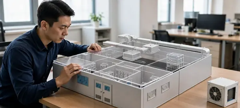
Service access after the fact is far more expensive adjusted for time than including service access during construction. Contamination risk is greater and emergency repair times get longer.
Maintainability vs. Reliability
Reliability represents the frequency of equipment failure. Maintainability indicates the ease and safety of returning the equipment to full operational capacity after failure or routine maintenance.
Every service component must be visible, reachable, removable, and verifiable.
Map Maintenance Tasks Before Defining Access Points
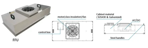
Each component in an ffu has different service needs and each individual FFU may have different service needs.
If the design for access is made for only one task, the paths for access to other service tasks may need to be built. To avoid this costly mistake, a complete task map should be prepared.
FFU Service Tasks
- pre-filter replacement
- HEPA filter change
- Motor / fan service
- Electrical control troubleshooting
Sensor Service Tasks
- Routine reading verification
- Calibration adjustment
- Probe replacement
- Tubing leak and blockage check
Task Definition Data
- Component identity & access direction
- Isolation & personnel requirements
- Functional verification steps
- Release authority & records
Top-Side FFU Access: Advantages and Limits
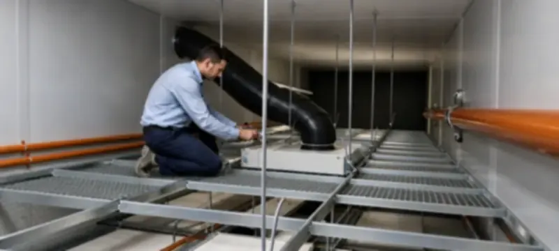
With a proper technical plenum, FFU top-side access can minimize the frequency for personnel to enter the cleanroom. It does not prevent downtime or the need for airflow to be tested after service.
When to Use Top-Side Service
Top access service only is suitable for high ceiling environments with a plenum and integrated electrical systems where frequent service of motors and filters is performed.
For low ceiling areas with plenum and controls and a high service integration of filters, airflow, and motors, side access or below ceiling service is preferred.
Key Limitation: Post-change filter integrity testing is still required to confirm the integrity of a filter seal if a filter seal is breached despite access being provided on the top side.
Top-Side vs. Room-Side Gel-Seal FFU Comparison
| Parameter | Top-Side Gasket Seal FFU | Room-Side Gel-Seal RSR FFU |
|---|---|---|
| Typical application | New build with deep service plenum | Retrofits, low-plenum facilities |
| Min. plenum clearance | 800 mm | 400 mm above unit |
| Filter change location | From ceiling plenum | From inside cleanroom |
| Typical filter change time | 60–90 min per unit | 30–50 min per unit |
| Contamination risk | Lower (personnel outside clean zone) | Controlled with proper procedure |
| Catwalk requirement | Required for safe access | Not required |
| Top-Side Gasket Seal FFU |
|---|
| Use: new build with deep service plenum |
| Min. plenum: 800 mm |
| Filter change: from plenum side |
| Room-Side Gel-Seal RSR FFU |
| Use: retrofits, low-plenum spaces |
| Min. plenum: 400 mm |
| Filter change: from inside cleanroom |
Clearances, Walkways and Load Safety for FFU Service
Access openings must be larger than the equipment’s overall dimensions. The access openings must take into consideration cover swing, the ability to fully extract the equipment, the ability to reposition tools, cable bend radius, and the posture of the personnel that will be working in that access opening.
ICs-card">
Key engineering Clearance Metrics
- FFU top service clearance: 600–800 mm minimum vertical extraction space above unit
- Catwalk width: minimum 600 mm wide main service walkway
- Catwalk loading: minimum 150 kg/m² uniform design load
- Room-side service zone: 1.2 m clear radius around FFU for gel-seal filter change
- Cover swing: account for full open position of hinged access covers
Key Safety and Load Considerations
Do not rely on ceiling grid support or FFU housing support for personnel loading. Walkable systems require specialized design and support with Walkable Load Certification.
Electrical isolation, lockout/tagout, lighting, and edge protection must meet site-specific safety standards, regulations, and requirements.
Engineering Pitfall: Missing Local LOTO Switch
Many designs provide only centralized FFU control at the main panel, resulting in omitting local lockout/tagout switches next to each unit in the plenum. This poses an electrical risk to personnel working on the ceiling cavity motors.
Engineering Pitfall: Non-Walkable Ceiling Abuse
Improvised walkways made of planks on T-grid ceilings cause long term deflection of the grid, break the integrity of the seals, and introduce HEPA leaks at frame edges. This is often only identified during certification testing.
Sensor Calibration Access: Accuracy and Accessibility
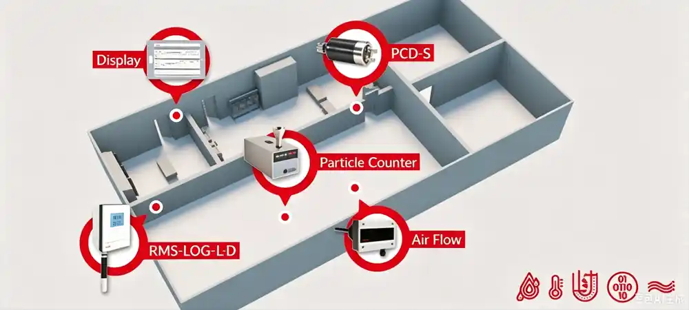
The sensor must be installed in a spot that accurately reflects the conditions in the cleanroom. You can’t sacrifice measurement accuracy just to make calibration easier. Moving a sensor to a corridor for calibration access can introduce response lag, sampling bias, and systematic errors.
Sensor-Specific Design Rules
- Differential pressure: include test ports and clear side identification; verify tubing runs for leaks and blockage
- Temperature & humidity: allow probe removal while maintaining representative location
- particle counters: keep sample lines short, straight, and of approved material
Sampling & Sensing Installation Rules
- Particle counter sample tubing: max 2 m length; minimum 150 mm bend radius; no sharp 90° bends
- Sample tubing material: plasma-cleaned stainless steel or conductive Tygon only
- Pressure tap location: do not place directly in FFU supply jet; use static pressure wall pickup
- Calibration interval: based on drift history, not a uniform facility-wide schedule
Calibration intervals are not a uniform frequency across the facility; they depend on manufacturer data, observed drift, and process risk.
Measure Total Maintenance Cycle Time
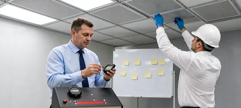
Fast component removal does not imply that the downtime during production will be short. The entire service cycle requires isolation, the preparation of access, gowning, work, the cleaning of the workspace, the functional verification, and the final release.
Full-Cycle Time Principle
Total maintenance downtime = isolation & preparation time + access & work time + verification & cleaning time + release hold time.
Improvements in design should be judged based on downtime for the entire service cycle, and not just based on the speed of removal.
15%
25%
30%
30%
Isolation & preparation Access & gowning Hardware change & calibration Verification & release
Hardware replacement is only 30% of total downtime. Access design determines the other 70%.
Case Snapshot: Bio-Pharma Cleanroom Access Retrofit
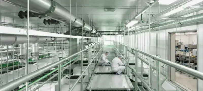
In Suzhou, China, a Pharmaceutical manufacturing facility had a clearance of only 700 mm in the plenum above the FFUs. The facility also had gasket-seal units that required 2.5 hours to change a filter due to the requirement of a plenum entry.
Deiiang™ modified the units and incorporated a room-side gel-seal RSR configuration, which has quick-release motor mounts and a pneumatic lift sealing mechanism.
Retrofit Results
- Filter change time reduced from 2.5 hours to 40 minutes per unit
- No plenum entry required for standard filter service
- Post-change integrity verification completed from the room side
- Overall maintenance cycle time reduced by over 65%
Deiiang Product Serviceability Criteria
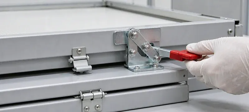
Serviceable design is supported by Deiiang FFUs and sensor design through communicated service dimensions, calibration access, and orientation.
Deiiang Service Design Features
- Quick-release motor mount for tool-free fan removal
- Pneumatic lift gel-seal mechanism for room-side filter change
- Standardized calibration ports with clear identification labeling
- As-built service documentation with access direction per unit
Considerations include the size of the housing, the distance a component must be moved in order to clear the housing, the distance and placement of electrical connectors, and calibration port placement. These factors are included in maintenance guides and support of commissioning activities.
Plenum Maintenance Space Evaluator
Determine whether your ceiling plenum has enough clearance for safe servicing of the FFUs.
Rating:
Walkway Recommendation:
Floor Loading Requirement:
Design Review Checklist and FAQs
Pre-Construction Design Checks
- Verify access path, tool swing, and largest component removal envelope
- Confirm electrical isolation, calibration access, and identification labeling
- Define functional checks, cleaning requirements, and release authority
Common Questions
| Question | Answer |
|---|---|
| Are all FFUs suitable for top-side filter change? | No. Suitability depends on model, plenum design, and filter type. |
| Does top-side service eliminate downtime? | No. Isolation, verification, and balancing may still require production pause. |
| How much ceiling clearance is needed above FFUs? | 600–800 mm for top-access; 400 mm for room-side gel-seal types. |
| Do sensors always need in-room calibration? | Some designs support remote calibration, but representativeness must be verified. |
| Are all FFUs suitable for top-side filter change? |
|---|
| No. Suitability depends on model, plenum design, and filter type. |
| Does top-side service eliminate downtime? |
| No. Isolation, verification, and balancing may still require production pause. |
| How much ceiling clearance is needed? |
| 600–800 mm top-access; 400 mm room-side gel-seal. |
The speed with which a part is removed is less important than the time it takes to return an area to a validated production state.
To perform a maintainability review for a specific construction project, submit your layout, ceiling section, and equipment list to Deiiang engineering.