+86 13638632902
 Jason@cleanroomequips.com


 MENU
MENU
Energy intensive cleanroom HVAC system use 30 to 75 percent of cleanroom energy. Within HVAC systems, fan filter unit speed control is the most significant factor impacting energy use.
The following article details use of Variable Frequency Drives integrated with intelligent control strategies to curtail cleanroom HVAC energy without compromising the cleanroom environment or integrity of the process.
The following article details the use of ffu speed control, HVAC system VFDs, and intelligent automation to maximize cleanroom energy efficiency.
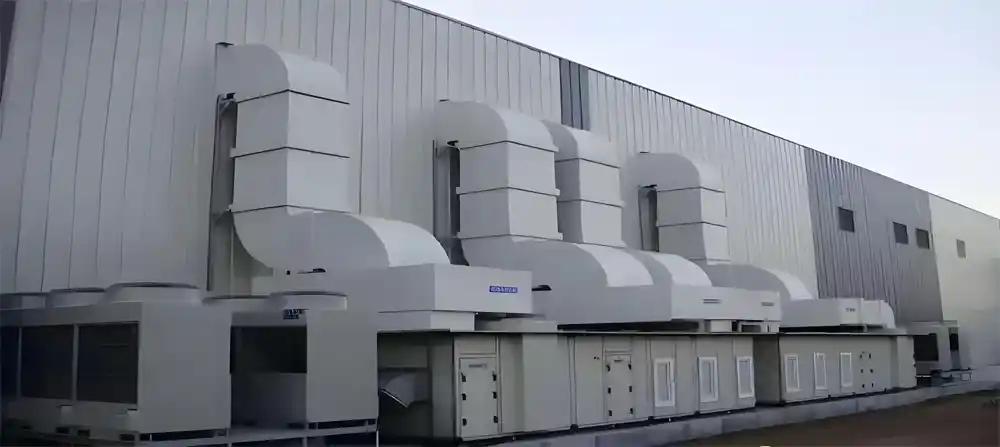
Why Cleanrooms Consume So Much Energy
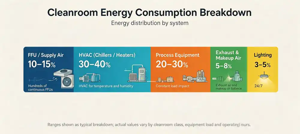
Cleanroom Energy Consumption Breakdown
Cleanrooms use more energy than a conventional building by large margins. There are a number of processes that contribute to this, including high air change rates, constant air recirculation, and stricter environmental control.
The following table shows the energy flows of a typical pharmaceutical or semiconductor cleanroom. Cleanroom energy efficiency starts with understanding where the power goes.
| System Component | % of Total Energy | Notes |
|---|---|---|
| FFU / Supply Air | 10–15% | Hundreds of continuous FFUs |
| HVAC (Chillers / Heaters) | 30–40% | HVAC for temperature and humidity |
| Exhaust & Makeup Air | 5–8% | Exhaust air and makeup air balance |
| Lighting | 3–5% | 24/7 |
| Process Equipment | 20–30% | Constant load impact |
| Component | % Energy | Notes |
|---|---|---|
| FFU / Supply Air | 10–15% | Hundreds of FFUs |
| HVAC | 30–40% | Temp & humidity |
| Exhaust / Makeup | 5–8% | Balance |
| Lighting | 3–5% | 24/7 |
| Process Equipment | 20–30% | Constant load |
FFUs can make up 30–40% of total HVAC energy. In semiconductor fabs, ventilation energy consumption constitutes 25.3%–46.6% of total fab HVAC energy and 7.2%–13.3% of total fab energy.
These figures highlight the importance of FFU speed control and cleanroom HVAC VFDs for energy-efficient cleanroom design.
Constant Speed Control Issues
Fan systems deployed for air cleaning, room pressurization and air circulation in most cleanrooms run at constant speed irrespective of actual requirements.
- Constant high speed operation overnight
- Constant 100% operation while production lines are idle
- No ability to control airflow
- Filters clogged and fan speed increased as work around
- No energy/performance data
One microelectronics company found that their cleanroom circulation fans operated at 100% while dampers were used to balance the flow of air, with the end result being increased wasted energy. The company was able to implement significant savings and an improvement to their particle counts by replacing their circulation fans with VFDs.
VFDs, FFUs, and Intelligent Cleanroom Control Systems Explained
What is a VFD in Cleanroom HVAC?
A variable frequency drive, or VFD, is a system that allows precise control of the speed of the motor by transforming fixed frequency electrical power to variable frequency.

In cleanroom HVAC systems, a VFD for cleanroom HVAC allows:
- Controlled airflow and static pressure
- A soft start/stop to minimize wear and tear on components
- Communication with building management systems (BMS) through Modbus, BACnet or other protocols
- Mitigated inrush current when starting the motor
FFU Speed Control
Controlling FFU speed isn't limited to simply telling the fans to slow down. A typical control loop consists of:
- Determining the cleanliness, pressure, and airflow needs
- A sensor gathers data in real-time (pressure, particle counts, filter differential, etc.)
- The controller checks what the setpoint is and what the current actual value is
- The VFD or FFU driver receives a command to adjust speed
- The fan speed increases or decreases
- The system records the current operating status and any alarms that are triggered
Some of the key parameters observed include: the desired airflow, actual airflow, room pressure, filter pressure differential, temperature, relative humidity, particle counts, fan parameters (i.e. frequency, current, power, and fault status), and alarm status.
The Core Principle: Fan Affinity Laws
Power savings with variable frequency drives (VFDs) on cleanroom HVAC system fans can be understood with the Fan Affinity Laws:
- Flow and speed: 10% reduction in fan speed equals 10% reduction in airflow.
- Speed and pressure: 10% reduction in fan speed equals 21% reduction in system pressure.
- Speed and power: 10% reduction in fan speed equals 27% reduction in power consumption.
Theoretically, fan speed reduction from 100% to 80% can reduce power to 51% of the original (0.8³ = 0.512). Real savings are impacted by system resistance, motor efficiency, control stability, and operational conditions.
| Speed (%) | Theoretical Power (% of full) |
|---|---|
| 100% | 100% |
| 90% | ~73% |
| 80% | ~51% |
| 70% | ~34% |
| 60% | ~22% |
| Speed | Power |
|---|---|
| 100% | 100% |
| 90% | ~73% |
| 80% | ~51% |
| 70% | ~34% |
| 60% | ~22% |
Actual performance will vary at speed settings due to factors such as resistance, motor efficiency, control stability, and operational conditions.
How Intelligent Control Improves Cleanroom Energy Efficiency
The placement of a VFD will not by itself guarantee energy savings. To ensure energy-efficient operation of cleanroom systems, an integrated and intelligent control system is necessary.
This includes: sensors, controllers, VFDs or FFU drivers, communication modules, monitoring software, alarms, and data logging equipment.
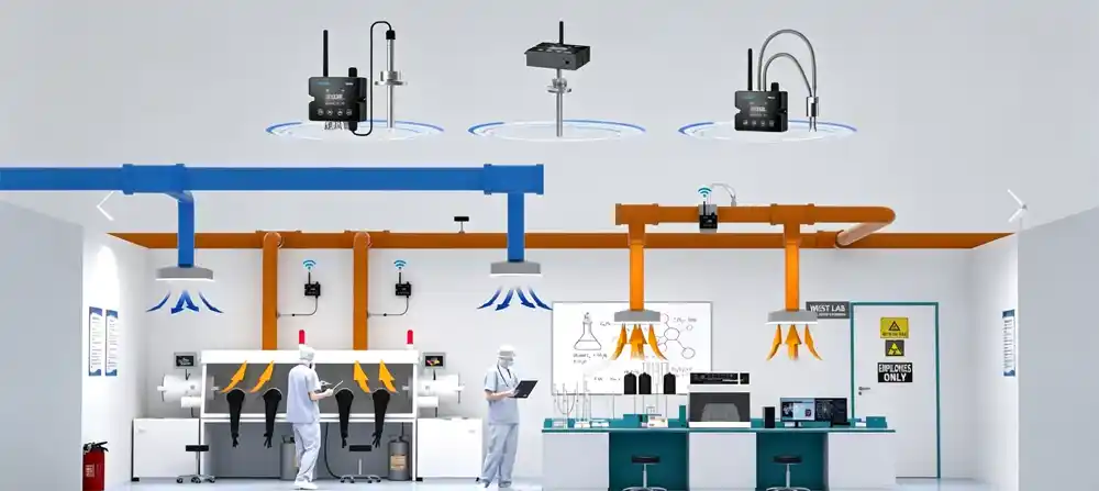
Typical Control Modes
Mode 1: Constant Static Pressure Control
This is applicable for systems that are ducted and have supply zoning. A duct pressure control is a static pressure control that acts once the terminal demand is reduced, then the fan is operated at a lower frequency.
Mode 2: Room Pressure Differential Control
This is crucial for cleanrooms that need to be positive or negative, when compared with the surrounding rooms. This adjusts the control of the fan speed to the necessary differential pressure.
Mode 3: Zone-Based FFU Control
Different areas of production can have varying load profiles. FFU zone-based speed control allows for high-demand areas to operate at a higher speed while low-demand areas can operate at a lower speed.
Mode 4: Production-State Control
Each preset mode (Production, Standby, Night, Maintenance, Emergency) determines FFU speeds, pressure setpoints, volumes of fresh air, temperature and humidity, and threshold limits for alarms.
Integration of BMS and Data Platforms
Today's systems enable the user to see the operational status of each FFU and how the FFU is operating in real time (e.g., current, frequency, power). Systems are able to record fault codes and create energy trend graphs. They support remote alarms and can be incorporated into the BMS/MES systems.
The most common communication methods are Modbus RTU, Modbus TCP, BACnet/IP, and Ethernet.
Deiiang Intelligent VFD and FFU Control Solution
Deiiang™ has the most complete offering for FFU speed control and VFD for cleanroom HVAC. The system has been designed by author Jason.peng.
The innovative system design provides an integrated system of sensors, controllers, VFDs, FFU drivers, and a centralized system management.
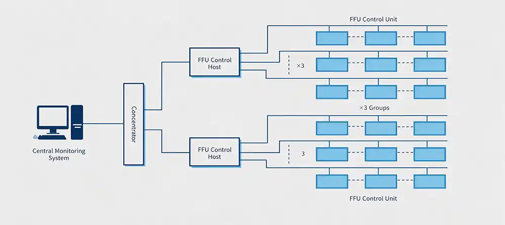
Solution Architecture
- Sensors: Measuring differential pressure, temperature and humidity, airflow, particulate matter, and pressure drop across filters
- Deiiang Controller / Communication Module
- VFDs, FFU Drivers, and Fan Control Units
- HMI / BMS / Energy Management Platforms
Core Functions
- Multi-zone control: Allows for each cleanroom zone to be independently controlled
- Variable speed regulation: Automatically changes based on pressure, airflow, or operational mode
- Status monitoring: Offers a real-time display of frequency, current, operational status, and alarms
- Communication integration: Allows for Modbus and general protocol integration
- Operating mode switching: Production, Standby, Night, and Maintenance modes
- Fault protection: Overcurrent and overvoltage, overheating, loss of communication, etc.
- Data logging: Energy and operational data logged and retained
- Scalability: More fans, sensors, or control zones may be easily added
Verified Product Data
The following table summarizes the details of the Deiiang™ product line:
| Parameter | Deiiang Data Reference |
|---|---|
| Compatible Fan Types | AC / EC / Centrifugal (Product spec) |
| Input Voltage | 220V / 380V, 50/60 Hz (Product spec) |
| Power Range | 0.55 – 160 kW (Product spec) |
| Frequency Range | 0–120 Hz (stepless) (Product spec) |
| Control Method | V/F, Vector, PID (Product spec) |
| Communication Protocols | Modbus RTU, Modbus TCP, BACnet/IP (Comm. manual) |
| Protection Class | IP20 / IP54 (optional) (Certification) |
| Operating Temperature | –10°C to +50°C (Product spec) |
| Warranty | 24 months (Commercial) |
| Parameter | Reference |
|---|---|
| Fan Types | AC / EC / Centrifugal |
| Input Voltage | 220V / 380V, 50/60 Hz |
| Power Range | 0.55 – 160 kW |
| Frequency Range | 0–120 Hz (stepless) |
| Control Method | V/F, Vector, PID |
| Protocols | Modbus RTU/TCP, BACnet/IP |
| Protection | IP20 / IP54 (optional) |
| Temp. Range | –10°C to +50°C |
| Warranty | 24 months |
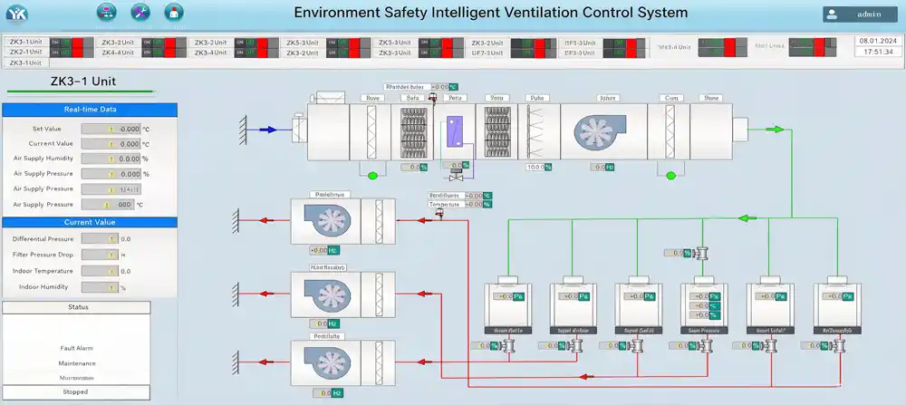
Case Study: High Precision Electronics Cleanroom Energy Optimization HVAC Systems
Representative Project Example — Case Study (Anonymized)
Project Overview
- Location: East Asia
- Industry: High Precision Electronics Manufacturing
- Cleanroom area: ~3,500 m²
- cleanliness class: iso class 6 and 7
- FFU count: 420
- AHU count: 8
- Operation: 24/7, 365 days/year
- Pre-Retrofit Control: Speed Control at Full Speed
- Retrofit Goals: Energy efficiency, stabilize pressure differentials, lower maintenance, and better visibility
The facility is in round-the-clock operation, but the production schedule has large gaps between load. The original system put all the fan runs at 100%, which ran the fans at a large waste of energy when demand was low.
Persona: Cleanroom Facility Manager Mr. Zhang
KPIs: Energy, downtime, cleanliness compliance, alarm response time, maintenance. Daily Concerns: Fan filter units at full speed during low demand, failure to identify the cause for low demand unit / system failures, concern for cleanliness pressure.
Key Concerns: Zone control, fan speed control, alarm systems, failure alerts, simplistic upkeep, and building management system integration.
Use Case: At 10:00 p.m. the production line operates at a low demand level. The clean room maintains operation but fewer personnel and tools are in the clean room. For a lack of demand based control, FFUs and central fans operate at the speed set for daytime operation. The intelligent control system will:
- Know that production mode has changed
- Ensure that pressure and airflow remain
- Step down target frequency
- Control the pressure and continue measuring the particle count
- Return to the default safe mode if control limits are exceeded
- Track the system state for control limits
Project Risks
Risk 1: Continuous operation of all systems and processes.
Approach: System/process based construction, off-site assembly and operational testing, fully assembled and functional system turnover during maintenance, bypass / manual emergency mode, one functional unit / zone at a time, and operational qualification after each phase.
Challenge 2: After a reduction of speed, how to keep a clean environment.
Solution: Validate the lowest airflow rate and the lowest airflow rate with appropriate frequency, conduct room pressure differentials with particle counts, determine TSI for critical safety zones, and deploy automatic recovery systems.
Challenge 3: Legacy system integration.
Solution: Check the motors and system specifications including, but not limited to, dimensions and requirements for installation.
Challenge 4: Different needs per area.
Solution: Implement priority control systems for critical zones, and unified control systems for general areas with prioritized controls and flexible modes.
Deiiang Solution
- Energy Audit and Baseline: Measured fan fluctuations, current and power input, pressure in the room, the number of filter fan units, pressure drops across filters, temperature and humidity, production scheduling, and operating hours.
- Zone Based Control FFU Groups: Split the clean room into high demand production zones and low demand production zones, as well as the transition zones, material zones, and standby zones, with adjustable pressure and speed, modes, and alarm thresholds.
- Dynamic Speed Control with VFD: Modulated based on pressure drop across the filters within a time schedule.
- Monitoring and Alarms: Equipment alarmed for faults and interruptions, alarms for pressure differentials, filter clogging, protection against over current, temperature, and humidity.
Comparison of Data Before and After Retrofit
| Metric | Before Retrofit | After Retrofit | Conditions During Test |
|---|---|---|---|
| Mean Fan Frequency | 50 Hz | 38 Hz | Mode of Production Same |
| Mean Input Power (FFU Array) | 142 kW | 78 kW | Conditions of Test Time |
| Daily Energy Used by FFU | 3,408 kWh | 1,872 kWh | Operated Continuously |
| Pressure Difference Between Rooms | 22 Pa | 21 Pa | Within Specification |
| Particle Count (iso 6) | 2,800 particles/m³ | 2,100 particles/m³ | ISO Class Same |
| Response Time to Alarm | ~8 min | <2 min | Log of System |
| Metric | Before | After |
|---|---|---|
| Mean Fan Frequency | 50 Hz | 38 Hz |
| Mean Input Power | 142 kW | 78 kW |
| Daily Energy (FFU) | 3,408 kWh | 1,872 kWh |
| Pressure Diff. | 22 Pa | 21 Pa |
| Particle Count (ISO 6) | 2,800/m³ | 2,100/m³ |
| Alarm Response | ~8 min | <2 min |
How Energy Savings Were Calculated:
- Energy use baseline before retrofit = 3,408 kWh/day
- Energy use after retrofit = 1,872 kWh/day
- Energy savings = (3,408 − 1,872) ÷ 3,408 × 100% = 45.1%
Calculation of Annual Savings:
- Annual energy savings = (3,408 − 1,872) × 365 = 560,640 kWh/year
- Local industrial electricity price = $0.12/kWh
- Annual savings = 560,640 kWh/year × $0.12 = $67,277
Simple Payback:
- Investment for retrofit = ~$98,000
- Payback time = $98,000 ÷ $67,277 ≈ 1.46 years
Operating conditions, electricity prices, and the scope of the project can change actual savings and payback. Data should always be validated by actual measurements.
VFD Retrofit for Cleanroom
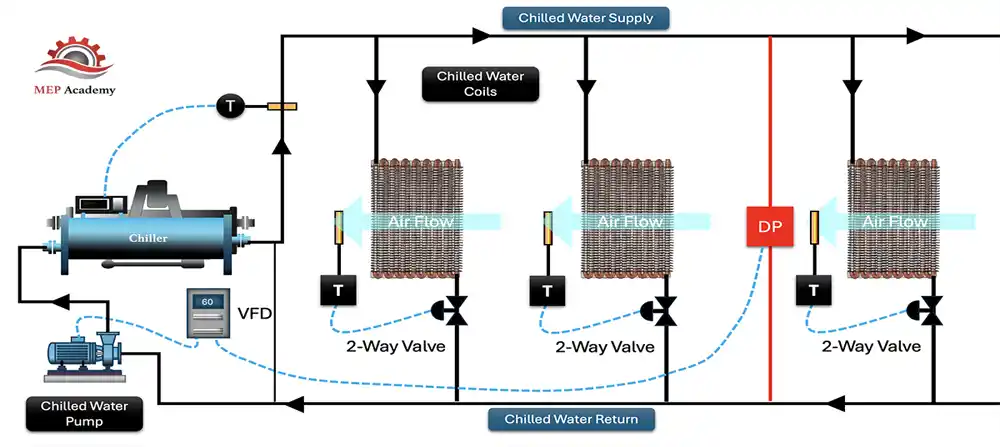
Step 1: Site Survey
Determine type of cleanroom, cleanroom class, room size (including length and width), number and arrangement of FFUs, configuration of AHU and MAU, make and model of fan with specified motor, location of control cabinets, number of sensors, whether or not a BMS exists, level of electrical documentation, and any operating data.
Step 2: Determine Energy Baseline
Collect data on what a typical weekday looks like, low load night and weekend data, full production data, frequency and time for fan, as well as current, power, room pressure, temperature and humidity, and tests related to clean room and air quality.
Step 3: System Design
This includes the selection of the VFD, the design for the control cabinet, cable and wiring design, the sensing placement, design of the control loop, design of the communication network, the plan for the BMS interface, the design of interlocks, the plan for emergency modes of operation, and the manual control and bypass plan.
Step 4: Factory Pre-Assembly and Testing
This involves the assembly of the control cabinet, the inspection of wiring, communication testing, sensor signal simulation, alarm and delay testing, background testing, logic control testing, and the Factory Acceptance Testing (FAT).
Step 5: On-Site Installation
This involves the installation of control cabinets and VFDs, placement of control wiring, installation of communications wiring, the labeling of wiring, grounding and Electro-Magnetic Compatibility (EMC) inspections before the control cabinets are integrated with the structures.
Step 6: Commissioning and Validation
This includes the testing of the control system for one unit, for the BMS, to validate all modes of operation.
Step 7: Delivery and Training
This includes delivery of the BMS and the VFDs with the required documentation and training for all modes of operation.
Cleanroom Design Requirements Before Using VFDs
Different ISO classes require different controls; pharmaceutical, semiconductor, and laboratory applications have different processes and needs. Critical process zones are just not energy saving zones. The design team, the validation team, and the facility owner must mutually agree on the minimum airflow requirements.
Safety Strategies That Must Be Incorporated
- Minimum operating frequency limits
- Pressure differential low-limit alarms
- Particle count exceedance alarms
- Fan fault interlocks
- Sensor failure handling
- Communication interruption handling
- Automatic recovery or safe mode
- Manual bypass mode
- Critical zone priority air supply
Filter Resistance and System Impact
Fans must operate at higher and higher frequencies to overcome increased resistance brought on by clogged filters, resulting in increased energy use. Pressure drop data across filters may determine when a filter is at its end of life and should be replaced. Increasing frequency to overcome clogged filters is not a viable long-term strategy.
Electrical and EMC Requirements
VFD harmonics, electromagnetic interference, insulation of the motor, shielded cables, grounding, the use of input/output reactors, bypass schemes, control cabinet cooling, the protection class, and the local electrical codes must be accounted for.
Cleanroom VFD Project Cost and Procurement Considerations
Project Cost Structure
A full price must include more than just the purchase costs of VFDs or FFU drivers. The total project includes:
- FFU drivers or VFDs
- Controllers and communication modules
- Sensors
- Control cabinets
- HMI or monitoring software
- Cables and accessories
- Design fees
- Installation fees
- Commissioning fees
- Cleanliness validation fees
- Training fees
- Spare parts
- Maintenance and after-sales support
Factors Influencing Quotes
The quantity of FFUs, fans, zones, motors, control cabinets, integration of BMS, remote monitoring, construction environment, night shift or shutdown, validation, and local electrical standards all influence the final quote.
Delivery Timeline
A typical process is: confirmation of the technical solution, confirmation of the parameters and drawings, procurement of the equipment, manufacturing of control cabinets, factory acceptance testing, packing and shipping, installation, commissioning with validation and HMI training for operation. The time required for each of these steps is influenced by the size of the project, the configuration of the installation, and the destination of the delivery.
VFD Pre-Purchase Checklist
Common Mistakes When Applying VFDs in Cleanrooms
Only focusing on the equipment purchasing price. Very cheap equipment, which is incompatible with the existing system, can lead to secondary retrofits, unplanned downtimes, communication failures, and long commissioning and maintenance.
Assuming theoretical savings are guaranteed. The laws of fan affinity indicate a tendency and not savings. The actual savings are based on operating time, speed range, system resistances, motor and filter conditions, control strategy, production mode, and tariff system.
No pre-retrofit baseline. Without a baseline, it is impossible to determine whether savings are achieved and if this influenced the cleanliness and what the savings or payback period of the project is.
Not adjusting AHUs when FFUs are adjusted. If FFUs are slowed and the central AHUs are kept at high static pressure, then total savings on the system would not be achieved. The operation of the entire system including FFUs, AHUs, MAUs, return-airstream and exhaust airstream and chilled water must be considered.
Neglecting Validation and Compliance. Any pressure control strategy needs to undergo validation and compliance checks with regard to room pressure, airflow and velocity, particle concentration, temperature and humidity, needs of the process, and the alarms and interlocks.
Frequently Asked Questions
Do VFDs bring down the energy consumption of cleanroom HVAC systems?
Yes, VFDs can lead to reductions in cleanroom fan energy consumption when the cleanroom is running in partial load. These savings can be very design and operational dependant. It is recommended to get power measurements at the site to confirm the savings.
Can FFU speed control be used in ISO-class cleanrooms?
Yes, as long as the system is properly designed, commissioned, and validated. Different control parameters are required for different ISO classes and different process zones. Speed reductions should always be validated.
Can VFD be used with all FFUs?
No, not always. Different FFU motors may have different drives, control interfaces, and rated parameters. EC fans and more traditional AC motors may have different control strategies.
What can a cleanroom expect for savings after a VFD retrofit?
There is no way to give a ballpark. Each retrofit's savings must be estimated by measuring the power consumption before and after the retrofit. Then, savings must be estimated by the number of hours the cleanroom is operating and by the cost of electricity. All of these data points are very dependant on the specifics of the project.
How long will it take to implement VFD in a cleanroom?
The time it takes to complete a project is dependant on how many pieces of equipment are in the cleanroom, how many control zones the cleanroom will be partitioned, the gaps in construction, how the Building Management System is implemented and how the system is validated. An accurate estimate for the duration of the project will be developed once the technical details of the project are confirmed.
Does the system support BMS integration?
The Deiiang™ systems support Modbus RTU, Modbus TCP, BACnet/IP and other standard integration protocols, however you must confirm with your Deiiang™ representative if a specific integration protocol is supported.
What do I need to fill out to receive a quote?
The following is needed to develop a quote: FFU count, fan and motor details, cleanroom dimensions, cleanroom iso classification, your control strategy, schematic drawings, BMS control statements, snapshot of the area, project address, the purpose and scope of the retrofit project, and the time estimate for project delivery.
Let's Get Smart on Cleanroom Energy Control
Using VFDs, we can now adjust fan speed to the actual demand, and our Intelligent Control system allows us to optimize and manage a fusion of airflow, pressure, production, and energy integration in one system.
A fully reliable cleanroom energy control retrofit should achieve all of the following in combination: savings in energy, operational stability, performance that can be verified, maintainability and expandability, no disruption to operations.
Deiiang™, Jason.peng's product, provides a total VFD solution for cleanroom HVAC and FFU speed control for semiconductor, pharmaceutical, electronics, and laboratory cleanrooms.
If so, please reach out to Deiiang™ and provide your fan specifications, control needs, and your target for energy savings. We will be able to assist you with assessing the control system and creating optimum solutions to your need for this project.
References
- iso 14644-1:2015 — Cleanrooms and associated controlled environments
- ASHRAE Handbook — HVAC Systems and Equipment
- IEA — Energy Efficiency in Cleanrooms
- Deiiang — When to Repair vs replace Your fume hood
© 2026 Deiiang™. All rights reserved. Designed by Jason.peng.