+86 13638632902
 Jason@cleanroomequips.com


 MENU

The design decisions made dictate the extent of the containment zone. The airflow is the limiting factor while lab technicians are using the hood.
The exhaust system is responsible for the removal of the toxins, and continuous monitoring shows that the design still works in 12 months.
In any trade-off, safety is more important than costs, noise and consumption. The fume hood is the main engineering implementation that protects people from airborne chemical substances.
Bad laboratory fume hood design brings chemical exposure problems, regulatory prescriptions and unanticipated downtime. The majority of failures connect to a lack of integration in the system.
This guide examines the design choices of the full process, from separate components such as the fume hood itself to complete building exhaust systems.
Application cases include pharmaceutical quality control and educational and research laboratories. Deiiang Cleanroom Technology Co., Ltd. provides the containment, exhaust, filtration and monitoring hardware that a hood depends on.
As product designer Jason.peng notes, lab fume hood ventilation requirements are based on the whole room, and not the fume hood alone.
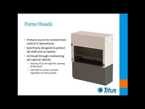
Laboratory Fume Hood Design: Core Functional & Safety Specifications
All laboratory fume hood design begins with chemical compatibility and airflow geometry, not the number from the catalogue. A hood that cannot withstand the right chemical will fail containment regardless of fan size.
The following must be taken into consideration when checking the specifications:
- Chemical compatibility matched to the proper substances used.
- The type of sash, glass composition and balance rated for daily use.
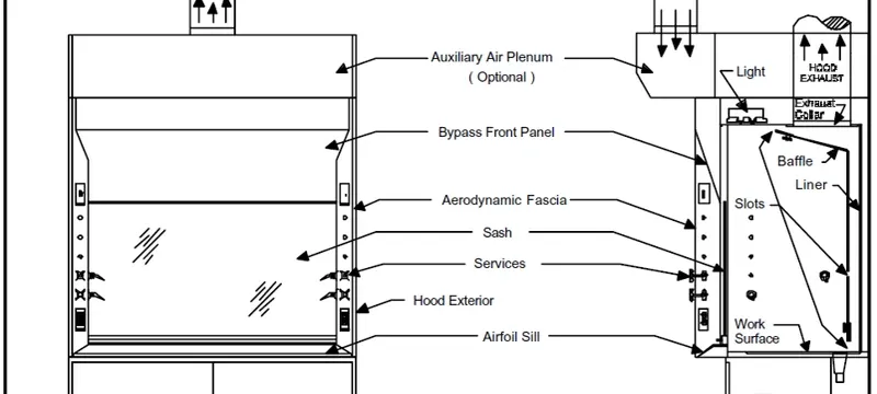
- A baffle shape that lets the rear slot work properly at low sash height.
- Proper equipment installation so airflow at the work opening stays unhindered.
- Service fixtures, sinks and gas appliances positioned outside the laminar flow area.
Deiiang is responsible for the room where the air is exhausted. Catalogue data indicate modular cleanroom panels with thicknesses of 50 mm and 100 mm and a practical width of 1150 mm. Fire protection is 60 minutes for MGO core and 120 minutes for the rockwool variant.
Chemical Compatibility & Structural Design Specifications
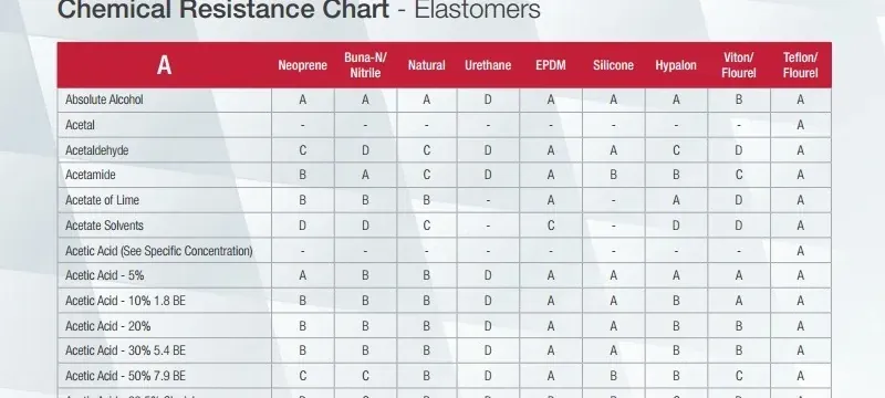
Epoxy-coated steel is ideal for all types of acids and solvents and holds dimensions up to 70 °C. Polypropylene is favorable for trace metal analysis, HF and hot perchloric digestion.
Baffle plates need to be constructed so their position can be adjusted, with slot width optimized for airflow maintenance.
If rear slots are too narrow then airflow is restricted when the sash is low. Excessive width produces an uneven flow speed across the opening. Proper sizing keeps airflow attACHed along the back wall.
- Epoxy resin top: general chemistry, moderate heating, 60 minutes of fire protection.
- Type 316 stainless steel: pharmaceutical and cleanroom purpose, easy to disinfect.
- PP worktop: HF and trace metals, no metal ion release.
- Spill containment lip: 12-19 mm, with an added 5 L tank wherever codes demand it.
Deiiang product designer Jason.peng reports that about 30% of material failures come from epoxy used in perchloric acid or trace metal applications. Liner material should be selected according to the provided chemical list.
Sash & Opening Geometry Design Principles
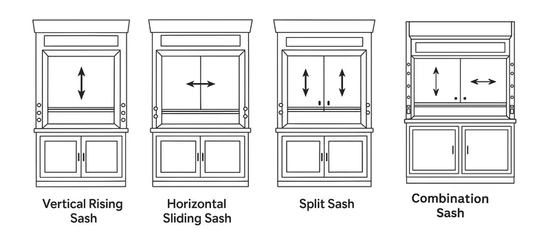
Vertical sashes are easy and seal well, while horizontal sashes minimize exhaust because the opening is smaller. Several laboratories combine both concepts into a single enclosure.
The maximum opening height is about 500-600 mm for a bench type fume hood and 750 mm for walk-in hoods. Sash stops can slip out of calibration after months of daily use, raising exposure risk.
A 25 mm airfoil with a rounded leading edge decreases boundary layer separation. It raises the uniformity of average face velocity by 8-12%, according to Deiiang airflow lab tests.
Fume Hood Face Velocity Design & Performance Calibration
Most fume hood face velocity design work centers on the average face velocity measured at the opening area.
At 0.4 m/s with an opening of 1.2 m by 0.5 m, airflow is about 0.24 m³/s, or 864 m³/h.
Velocity that is inadequate leads to fume leakage. Velocity that is too high creates turbulence that pulls fumes out of the hood.
ASHRAE 110 [3] uses sulfur hexafluoride tracer gas for containment measurement. A passing result shows no more than 0.1 ppm of tracer at the operator breathing zone.
Face Velocity Range Selection by Hazard Level
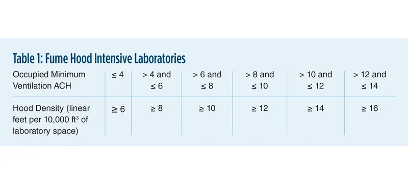
Table 1: Face velocity selection according to hazard level and position of sash
| Hazard Level | Face Velocity | Sash Opening | Typical Utilization |
|---|---|---|---|
| Low | 0.3 m/s | ≤ 300 mm | Teaching, low-toxicity salts |
| Medium | 0.4 m/s | ≤ 400 mm | General wet chemistry |
| High | 0.5 m/s | ≤ 400 mm | Carcinogens, strong acids |
| Radiochemical | 0.6 m/s | ≤ 300 mm | Handling of radionuclides |
| Hazard Level | Face Velocity | Application |
|---|---|---|
| Low | 0.3 m/s | Teaching, low-toxicity salts |
| Medium | 0.4 m/s | General wet chemistry |
| High | 0.5 m/s | Carcinogens, strong acids |
| Radiochemical | 0.6 m/s | Handling of radionuclides |
Higher maximum sash openings mean lower face velocity for the same exhaust volume. Always check velocity at the maximum allowed sash height for each hazard level.
Uniformity Testing & Calibration Protocols
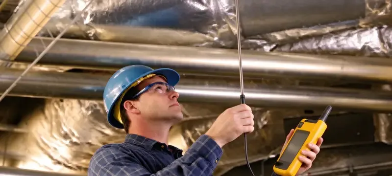
Uniformity is the measure that determines containment, not just the average value. The 9-point grid test introduces a 3x3 arrangement of the sash opening for measurement.
Acceptable variability is usually ±15% of the mean, with all cells at least 80% of the setpoint. Adjustment for sash height is performed before a pass or fail statement.
If uniformity fails, correct it in this order:
- Adjust the rear baffle to maintain equal airflow throughout the sash.
- Adjust inlet dampers on the hood branch duct.
- Reposition or remove obstructions inside the hood working zone.
- Cross-draft check: air speed within the sash should not exceed 0.1 m/s.
- The height of the sash should be registered each time readings are taken.
- Re-test after any change in duct, damper or fan.
Deiiang field data: the CCY11 differential-pressure transmitter holds 0.25% FS accuracy, 400 ms start-up and ±0.3% FS/year stability. It enables real-time face velocity tracking and alarm triggers, removing monthly manual spot checks in high-hazard labs.
Pre-test uniformity checklist:
Fume Hood Ventilation System Design & Ductwork Layout

Fume hood ventilation system design is critical to how the hood operates when filters load and sashes open.
Constant volume supply airflow to the hood, regardless of sash position, is wasteful. Variable volume air follows the sash and lowers duct static pressure and fan energy by 30-50% [11].
Lab make-up air must match exhaust volume within 10% at most for a safe working environment. If make-up air is insufficient, the hood is starved of airflow.
Make-up air vents should be placed to avoid cross-drafts at the fume sash opening. Supply air should enter low and return high for stable room airflow.
Duct material depends on the chemicals used: 316L stainless steel for solvents, polypropylene or fiberglass for acids, coated steel for general application.
Deiiang catalogue data: airtight and tight-seal oblique slide dampers hold leakage below 0.5% per JB/T 7228-94 [17]. Standard control dampers hold below 2%.
Face velocity at full-open damper position should not exceed 20 m/s, to avoid noise and vibration.
Fume Hood Ductwork Design Best Practices
Fume hood ductwork design follows a few hard rules that prevent condensation, noise and leakage.
- Slope horizontal ducts 1-2% toward drain points at low points.
- Insulate cold exhaust ducts to prevent surface condensation.
- Install drain traps of chemically resistant material matched to the exhaust content.
- Minimum duct velocity 7.5-10 m/s in horizontal mode to keep vapors flowing.
- Bend radius at least 1.5 times the duct diameter, with smooth internal joints.
- Leakage class B or better for hazardous exhaust types.
- Exhaust discharge at least 3 m above the building roof.
- Flexible connections at fan inlet and outlet to isolate vibration.
Deiiang installation data shows field-assembled ducts often have 2-3x higher leakage than factory-tested sections. Proper joint sealing is critical for hazardous duty systems.
Airflow Balancing & System Resistance Calculation
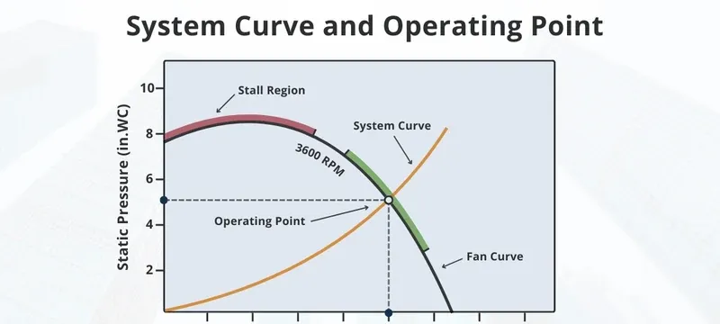
System resistance is calculated with the Darcy-Weisbach form: ΔP = f × (L/D) × (ρv²/2), where f is the friction factor and v the velocity.
For a 20 m long, 300 mm diameter duct at 8 m/s, friction factor 0.02 and air density 1.2 kg/m³: ΔP = 0.02 × (20/0.3) × (1.2 × 8²/2) ≈ 102 Pa.
Fitting losses are added separately as a K-factor multiple of velocity pressure.
Dampers should sit at least 1.5 times the valve width downstream and 0.5 times the width upstream for constant air volume valves, per Deiiang installation tolerances.
Fan head must be sufficient to overcome filter resistance. The initial pressure drop of an H13 HEPA filter at 1900 m³/h is under 200 Pa, and final pressure drop reaches 400-600 Pa when the filter is dirty.
Laboratory Exhaust System Design & Emission Control
The design of laboratory exhaust systems aims at ensuring the safety of the equipment operator and the building. The exhaust must eliminate harmful vapors, lessen their strength, and discharge them where re-exposure is impossible.
Exhaust cannot be overlooked as a normal utility. It is needed to keep a hood system safe.
Odorous or dangerous air has to be treated before discharge. Common methods include HEPA filters, chemical scrubbers and activated carbon adsorption.
Selecting the proper method depends on the type of contaminant, its concentration and local discharge standards.
Exhaust Fan Configuration & Redundancy
An N+1 fan redundancy system allows operations to continue when a fan is out of order. Motors used in hazardous environments should meet explosion-proof standards where flammable vapors are present, backed by emergency power.
Direct-drive fans avoid slippage and require less maintenance than belt-driven systems.
In the Deiiang university teaching laboratory project, a backdraft damper was used at the fan, a counterweight pressure-relief damper in the laboratory, a constant volume air valve per duct and a rectangular 800 mm silencer.
Project-reported results show face air velocity of 0.4 m/s, ±10% velocity uniformity and a sound level of 62 dB(A) at 1 meter.
Emission Dilution & Stack Design Standards
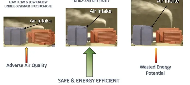
- Minimum stack height of 3 m above the roof, and 15 m away from any ventilator intake.
- Exit air velocity of 10-15 m/s to dilute and avoid downwash.
- A rain or conical cap that does not limit airflow.
- Downwash prevention by avoiding eddies at roof edges and tall structures.
Local regulations may impose higher stacks and lower discharge concentrations. Roof edge downwash risk increases with building height and wind speed.
Chemical Fume Hood Ventilation Best Practices & Safety Standards
Chemical fume hood ventilation best practices combine sound procedures with reliable equipment. A hood can pass commissioning but fail if someone leaves the sash open or props the door.
Containment assurance includes tracer-gas testing, velocity alarm installation and yearly recertification. GMP facilities add written calibration and change control procedures.
"The bigger the fan, the better the containment."
Fact: An oversized system means more turbulence and noise without better containment.
"Face velocity is the only figure worthy of attention."
Fact: Uniformity and cross-draft speed also affect real containment.
"VAV hoods are more hazardous than CAV ones."
Fact: Correctly functioning VAV systems keep velocity across sash travel and alarm on failure.
"Ductless fume hoods are as good as ducted ones."
Fact: Ductless hoods filter only certain chemicals and need frequent filter replacement, so they are not suitable for hazardous work.
Compliance with Lab Ventilation System Safety Standards
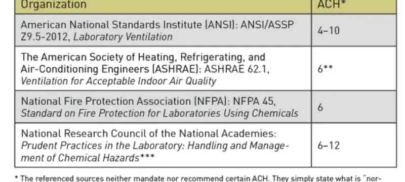
Table 2: Safety regulations and control specifications of laboratory ventilation systems
| Regulation | Area of Activity | Primary Control Specification | Typical Verification Frequency |
|---|---|---|---|
| EU GMP Annex 1 [14] | Sterile manufacturing | Contamination control system; airflow control | Annually + quarterly spot checks |
| FDA 21 CFR Part 211 [15] | Drug cGMP | Calibration documentation; change management | Annually + documented change control |
| iso 14644-3 [8] | cleanroom testing | Airflow; filter leakage; recovery testing | Every 6-12 months |
| GB 50073-2013 [13] | cleanroom design | Room pressure; air change rate; discharge | Annually |
| USP <797> [16] | Sterile preparations | iso class; hood location; airflow testing | Every 6 months |
| Regulation | Primary Control Specification | Verification Frequency |
|---|---|---|
| EU GMP Annex 1 [14] | Contamination control system; airflow control | Annually + quarterly spot checks |
| FDA 21 CFR Part 211 [15] | Calibration documentation; change management | Annually + documented change control |
| ISO 14644-3 [8] | Airflow; filter leakage; recovery testing | Every 6-12 months |
| GB 50073-2013 [13] | Room pressure; air change rate; discharge | Annually |
| USP <797> [16] | ISO class; hood location; airflow testing | Every 6 months |
Deiiang engineering teams regularly align GB 50073-2013 [13] designs with iso 14644 [8] requirements for multinational pharmaceutical clients, because lab ventilation system safety standards differ between markets.
Sustained Containment Operational Best Practices

Fume Hood Energy Efficiency Design Strategies
Fume hood energy efficiency design provides the best return on investment. A standard 1.2 m hood running around the clock at 0.5 m/s can move more than 2,000 m³ of air per hour.
Fan energy plus the external supply of conditioned air may exceed the cost of the hood itself.
All savings percentages below apply to constant-flow systems operating continuously at a face velocity of 0.5 m/s.
Deiiang catalogue data: a 592 × 592 × 292 mm H13 HEPA filter handles 1900 m³/h at an initial pressure drop under 200 Pa.
Final pressure drop reaches approximately 400-600 Pa. A V-bank combined activated carbon filter handles 3700 m³/h for odour filtration.
Variable Air Volume System Optimization
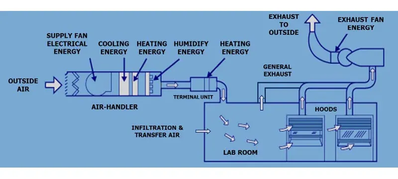
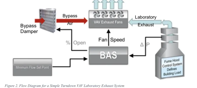
The VAV system uses three control loops. Sash height sensors send information to the hood controller, which resets branch airflow to hold the minimum flow level.
Duct static pressure reset lowers fan speed until the zone valve is almost fully open. Occupancy sensors reduce hood flow to the minimum level when the room is empty.
Minimum airflow should be set slightly above the containment floor, typically 30-40% of design flow.
The most widespread VAV failures include sash sensor drift, incorrect minimum flow settings and static pressure overshoot. Regular tuning prevents both energy loss and containment loss.
Deiiang electric actuators keep position stable within ±2% over 100,000 operations, preventing VAV calibration drift.
Heat Recovery & Waste Air Reuse Options
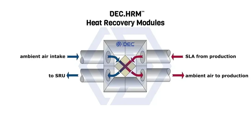
- Air-to-air heat exchangers give 50-70% sensible recovery without cross-contamination.
- Enthalpy wheels provide 60-80% total recovery and should only be used if exhaust air is non-hazardous.
- Run-around coils recover 40-60% and are safe for hazardous exhaust separation.
- Payback: three to seven years on average, subject to climate region and usage.
Heat recovery often conflicts with fume hoods whose exhaust requires separating noxious or bad-smelling emissions. That favors run-around coils rather than wheels.
Heat recovery is not suitable for acidic gas, high particulate levels, or VOCs above occupational exposure limits.
For annual savings, use the formula: annual savings = (CAV airflow − VAV average airflow) × hours of usage × energy cost per cubic meter. Deiiang can provide project-specific estimates.
Frequently Asked Questions
What is the recommended face velocity for a chemical fume hood?
0.4 m/s is the general standard, rising to 0.5 m/s or 0.6 m/s for more hazardous operations. Verify it with 9-point grid testing rather than a one-time measurement.
How often should fume hood ventilation systems be calibrated?
Start with annual calibration and repeat it after any change in duct, damper or fan. GMP sites usually add quarterly spot checks and documented alarms.
Can fume hood ductwork share a system with general lab exhaust?
No. Fume hoods must have a dedicated duct to avoid cross-contamination, and they must discharge through a separate stack.
What is the minimum exhaust stack height for a lab fume hood?
A minimum of 3 m above the roof and 15 m from air intakes, with local regulations taking priority. Exit speed should be 10 m/s or higher.
How much energy can a VAV fume hood system save?
VAV saves about 30-50% compared to CAV systems. Low-flow hoods add 20-40%, and occupancy sensors add another 10-15%.
What standards apply to pharmaceutical lab fume hood ventilation?
The main references are EU GMP Annex 1, FDA 21 CFR Part 211, USP <797> and the iso 14644 series, with additional help from EN 14175 [1][2] and ASHRAE 110 [3].
References
- [1] EN 14175-1:2003 Fume cupboards — Vocabulary.
- [2] EN 14175-3:2019 Fume cupboards — Type test methods.
- [3] ASHRAE 110-2016 Methods of Testing Performance of Laboratory Fume Hoods.
- [4] ANSI/AIHA Z9.5-2012 Laboratory Ventilation.
- [5] SEFA 1-2010 Laboratory Fume Hoods — Recommended Practices.
- [6] OSHA 29 CFR 1910.1450 Occupational exposure to hazardous chemicals in laboratories.
- [7] NFPA 45 Standard on Fire Protection for Laboratories Using Chemicals.
- [8] iso 14644-1:2015 / iso 14644-3:2019 Cleanrooms — Classification and test methods.
- [9] EN 1822-1:2019 / ISO 29463 HEPA and ULPA filters.
- [10] ISO 16890-1:2016 air filters for general ventilation.
- [11] ANSI/ASHRAE 62.1-2022 Ventilation for acceptable indoor air quality.
- [12] GB 50243-2016 Code for construction and acceptance of ventilation and air conditioning works.
- [13] GB 50073-2013 Cleanroom design code.
- [14] EU GMP Annex 1 (2022) Manufacture of sterile medicinal products.
- [15] FDA 21 CFR Part 211 Current Good Manufacturing Practice.
- [16] USP <797> Pharmaceutical compounding — sterile preparations.
- [17] JB/T 7228-94 Damper leakage classification.
- [18] GB/T 1804-2000 General tolerances.