+86 13638632902
 Jason@cleanroomequips.com


 MENU

If you ask HVAC servICe providers, you will see that dampers are not involved in the list when talking about energy consumption of the HVAC systems. Nevertheless, they are very important because it is these blades that regulate air supply in different spaces.
In other words:
- Manual dampers are used for balancing the system when it has been set up and do not change their position after that.
- Motorized dampers allow you to control airflow at any point in time or let the automation do it.
- Zoning dampers help you to save energy by supplying air only to certain zones.
JYg3uJsSNTo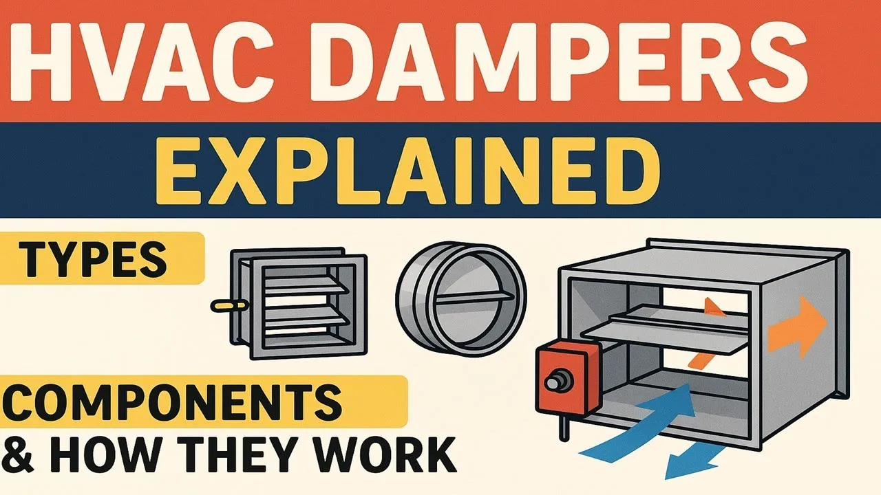
HVAC Dampers Are the “Airflow Managers” of HVAC Systems.
The practical use of these types of air dampers tackles three key factors at once: whether the air used is balanced, whether the zones maintain their pressure, and what the operating costs of the plant are.
A leak rate one would consider negligible on a specification sheet turns into tens of kWh of fan energy annually when multiplied by a dozen dampers operating for a total of 8,760 hours. Moreover, at clean rooms and laboratories one gets to deal with an extra problem, besides the financial aspect of the bill. The loss of pressure leads to a compliance issue.
The following text will describe how dampers work, how the main types of dampers behave, and what means of selection and maintenance have we adopted over a 15-year international practice in HVAC and cleanroom areas.
What is an HVAC Damper and Where is it Placed in the HVAC System?
The ANSI/AMCA Standard 500-D-18 provides a straightforward definition of dampers. Dampers are devices placed in ducts or openings which are there for the purpose of controlling air flow through a duct or opening. Dampers may be operated either manually or automatically.[1]
In simple words, dampers are the elements inside ducts that control the flow. The rating of water valves uses Cv coefficient while the rating of dampers deals with an air flow loss coefficient, known as Cd.
- Manual models dominate the field as they are only set one time during TAB (Testing, Adjusting and Balancing) and this setting remains unchanged.
- Fan discharge outlets have control dampers installed and utilized for opening and closing modulating operation. One rule that applies to this field is worth repeating: axes of the blades should be perpendicular to the shaft of the fan so that the pressure velocity is equally spread over the entire blade.[4]
- Outside air, exhaust air, and Return Air intakes are maintained by mud-operated dampers located in the unit. Energy codes make sure that those dampers have lower leakage than rest of the system.
- Fire and smoke barrier penetrations - where duct penetrates fire-rated wall or fire-rated floor slab, fire/smoke damper is used. Either a fusible link or smoke detection system signal closes the damper in order fire and smoke don't travel along the duct and penetrate the next compartment.[5]
Specification that distinguishes the dampers one from another, having the same size, is missed more often than not: free area, which is the amount of minimum area open between the blades and frame as a percentage to the total area of the front side of duct. More of free area results in a smaller drop in pressure at the maximum opening.
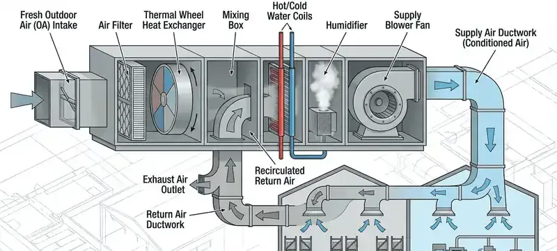
Fig.1. The positions of all damper types in the duct system of the AHU: outside air, return air, exhaust air, and fire barrier positions.
How Do Dampers Work?
The functionality of dampers can be summarized with one movement: the rotation of blades that reduces the opening area within the duct. When the blade moves from the completely open to completely closed position, the value of coefficient Cd begins to increase. It is interesting to note that for the majority of the moving process, the value of Cd increases significantly, which is something people tend to underestimate.
The definition is short:
Cd = ΔPt/Pv
In this formula ΔPt stands for the value of total pressure drop through the damper, while Pv represents local velocity pressure.
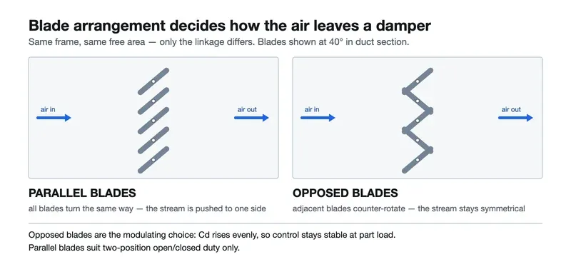
Two configurations of blades are the most widespread:
- Parallel dampers: All blades move in the same direction. Such a construction works similarly to the turning vanes and the resistance grows slowly when the damper is closing. This system works perfectly with two positions only: open and closed. For the effect to be linear, the system should lose 20-50% of its pressure when it is opened.
- Opposed dampers: The adjacent blades go in the opposite direction. Thus, the device works like orifice plate, and the resistance rises quickly. This is a far more viable option, as the system works with the loss of just 5-10% of its pressure.
Nevertheless, parallel dampers have been used in variable airflow box systems, which has caused some issues of control because the device starts oscillating between 30% and 60% travels during its operation.
The situation is easier to understand when we know the numbers. For instance, if we take the opposed damper and use it at L/R=0.8, we will find out that Cd reACHes around 60 times the maximum value at 40 degrees. At an angle of 60°, the flow resistance factor stands at 360, while at the angle of 80° this increases to 2,500.[6]
It is due to this fact that static fan calculation based only on fully opened damper has limited usefulness when it comes to branch balancing. In the case when damper is opened, its contribution is negligible. In the case when damper is not fully opened, damper represents the point of maximum pressure loss in the ventilation system.
Actuator powers blades in two ways: via crank arms and via linkages. When it comes to low and medium velocity systems you should assume that torque that will be produced should depend on the area of the actuator faced with airflow, e.g. 5 N·m/m², while actuator should not have area greater than 3 m². If it has to be larger than that you should divide actuator into separate sections.[6]
Do not even think about using larger actuators in the case of binding dampers. In most cases frame is not square, fastening is hitting the frame or there is an over driving of the dampers. Torque is not the issue here.
Types of HVAC Dampers: Manual, Motorized, and Zoning Dampers.
5ljXGWV9Fpk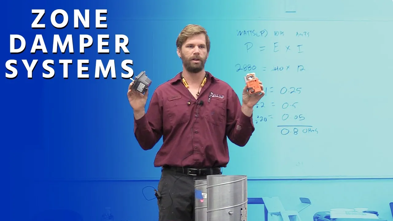
There are three main types of HVAC dampers, namely manual dampers, motorized dampers, and zoning dampers.
For instance, manual dampers use manual quadrants, cables, or gearboxes in regulating airflow.
Furthermore, motorized dampers come with mV or 0-10V actuators in regulating airflow.
In addition, zoning dampers entail using actuators and airflow measuring stations for regulating airflow.
In other words, manual dampers allow for system set-point balancing and are used without needing onsite adjustments.
Motorized dampers, on the other hand, come with a device capable of being controlled remotely.
Moreover, motorized dampers incur medium costs due to the additional components involved in operation.That represents a difference of 5 times.[2]
Clean room and high containment require complete enclosure with pneumatic EPDM blade seals. These seals have a static pressure rating of 1500 pa.[6]
Zoning as well as VAV dampers
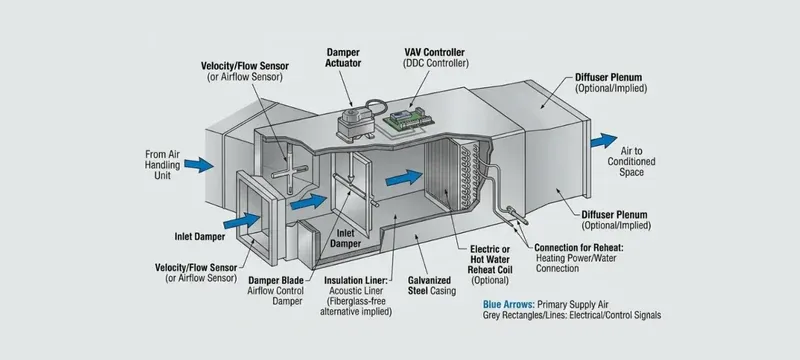
Zoning introduces a closed loop on top of everything already mentioned. A built-in air flow meters total and static pressure and converts the differential into CFM thus sending it to a controller. The controller regulates the damper in order to reach the pre-established values and sends information about the actual flow back to BMS for fan speed adjustment through the VDF.[2]
It is through that cycle of measurement, comparison and adjustment that significant energy savings can be achieved. The air flow management is based on demand which means that there is no need to push a fixed volume in each zone to cover varying loads. In cases of fluctuating occupancy and production loads frequent energy use reduction can be by 30% and more.
How to Choose a Damper? Why Do They Fail and What is the Maintenance Process?
The logic of selection: a four-step process
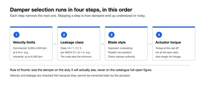
Selection of dampers is sequential and starts from defining the limitations of operation to calculating the dimensions of actuator.
- Determining velocity and static pressure limits ---- First work out max duct velocity as well as system static pressure. It is possible for commercial dampers to be categorized from 3000-4000 at 5-8 inches of water gauge while heavy industrial units can run at 6400 fpm at up to 20 inches gage. Exceeding the mentioned limitations leads to damages of the blade and supporting mechanisms not to mention potential noise pollution.[2][3]
- Determining leakage class ---- Check obtained values inChoose between parallel (for on/off in two positions) and opposed (for modulation) blade style. Next, consider damper authority, where the pressure drop of the fully opened damper, expressed as a percentage of the total pressure drop in the connecting duct is in the acceptable range: 20–50% for parallel and 5–10% for opposed.[7]
- The torque required for actuating and area of the damper must be determined. The size should not exceed 5 N·m/m² of face area and 3 m² of area for one actuator; otherwise, the installation must be done with modules linked together.[6]
Common Myths Debunked
MYTH 1
Damper leakage is insignificant for the performance of the whole system.
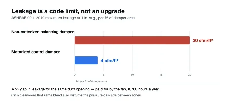
This is definitely not the case. Bad sealing has a direct effect on fan energy; moreover, it can cause the malfunction of the room pressure control system. ASHRAE 90.1-2019 separates two damper categories and sets the following Requirements for them regarding leakage at a pressure of 1; 20 cfm/ft² allowed for non-motorized dampers and only 4 cfm/ft² for motorized systems. For instance, a leak of 64 cfm (for a damper that is 24×24 inches) is equal to 950,000 m³ of air that enters the system yearly. The scale of leakage is critical for cleanroom operations, as it disrupts pressure gradient in a cleanroom.[2]
MYTH 2
Dampers are interchangeable, so it makes sense just to choose the cheapest ones.
Same sizes for the frame, but different pressure ratings: the basic manual balancing ones can maintain pressure up to 500 Pa, while motorized systems with full sealing can work under pressure over 1500 Pa. Seals may vary from not having them at all to inflatable EPDM blades.Choose the wrong rating or type of material for the job and you’ll end up with binding, leaking and an early death for your actuator.
Common Problems in the Field and Troubleshoot

Out of all the damper failures we are called for, almost all are due to installation and not manufacture.
| Symptom | Root Cause | Fix |
|---|---|---|
| Blade binding, incomplete movement | Frame not square; too-tight fasteners squeezing the frame | Check measures; loosen fasteners; re-indent frame |
| Will not shut properly, leak continuously | Worn blade seals; balancing damper does not have it | Install the right leakage class; do not use balancing damper for shut-off duty |
| Actuator burns out or gets overloaded | Torque too small; travel stop getting overloaded | Calculate the torque required; check travel limits; add the bearings for long-shaft |
| design static pressure is not realized | Fan designed using full-open damper data; system operates at a 30-45° angle | Calculate the pressure loss at angle; upsize the damper if necessary |
| Leakage near the perimeter of the frame | Unsealed duct connection; lack of support for an opening in the wall | Seal the frame connection with the duct; install an extra frame around the hole |
Maintenance Needs

NFPA requires fire-and-smoke dampers checked at least once a year, and twice a year for high-risk duty. The inspection checks for corrosion, blockage, full movement and real test.[5]
Dampers that control and balance could go without inspection for a year during the TAB re-verification.
HVAC Case Study: Changing Dampers in a Cleanroom.
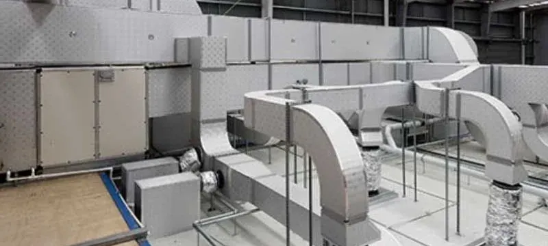
In the case of Deiiang, they have substituted an old series of manual dampers with advance networked control dampers being operated by a BMS.
According to the leakage ratio set by ASHRAE 90.1, the moving of 28 dampers from 20cfm/ft to 10cfm/ft means eliminating possible 950,000 m3 of leakage annually along with considerable fan usage and wasted conditioned air. The dampers are measured on real-time basis, which results in a more stable airflow.
Have an existing damper schedule?
If you possess an already existing schedule, you may get FREE leakage-class analysis and find out how much energy your system can save.
If you possess an already existing schedule, you may get FREE leakage-class analysis and find out how much energy your system can save.
FAQ
Q: What is the concept of dampers and how do they operate?
A: They control the airflow through adjusting blades in the ductwork. Changing the angle of the blades results in increasingly changing of the air volume.
Q: What types of dampers can be differentiated?
A: In the terms of actuation there are three kinds of dampers: manual balancing, motorized control and Zoning dampers or VAV characterized with feedback flow control. By blade type: single blade, parallel blade and opposed blade dampers.
Q: The importanceA: The damper is what will keep you inside the energy code leakage limits, providing you with stable control and preventing the use of fan power for unnecessary pressure drop and leakage.
Q: How often do dampers need inspecting?
A: Certainly at least once a year. Fire/smoke dampers and dampers for cleanrooms under critical conditions are two exceptions requiring a six-month cycle, with travel and leakage inspected.
Q: Do dampers actually save energy?
A: They do, unless they are part of a zoning scheme or VAV scheme that allows on-demand rather than constant volume airflow. Less conditioned air escapes through the seams with a lowered leakage class for the motorized units.
Download the complete guide to dampers
Sizing charts, leakage class specifications, and project examples.
Sizing charts, leakage class specifications, and project examples.
Summary.
Dampers are also duct gate, if you choose. Dampers, however they are referred to, are themselves the critical juncture on which all matters of airflow balancing, energy efficiency, and environmental compliance actually hinge.
Five things mostly affect the following:
- First, look for duct velocity and duct pressure before affordability. Exceeding the operating limit for a compressor system entails service life instead of a more affordable unit, plus an additional safety margin.
- Consider leakage class as a part of the code, leaving no room for upgrades. The gap between 4 and 20 CFM/ft² stacks up to hours upon hours a member of the fan runs.
- Use opposed blade dampers for all modulating applications. Parallel blade dampers ought to be used only in two-position applications.
- It is important to note that a control damper will not be a shutoff valve. The tight shutoff is determined by the seal class and construction of the frame, not by turning the blades to an angle of 0°.
- The travel is performed in closed-loop direction, i.e., measuring the flow, control through the direct digital control, and feedback from the fan speed. This allows the system to rebalance itself and ensure the demanded accuracy and efficiency using less energy.
When considering a building that will be evaluated based on energy efficiency in the future, the choice of dampers should be given special attention.
References
- ANSI/AMCA Standard 500-D-18. Laboratory Methods for Testing Dampers. Air Movement and Control Association International.
- Greenheck. HVAC Control & Balancing Dampers (catalog) 2019.
- Greenheck. Damper Selection Guide 2019.
- Greenheck. Product Application Guide. Industrial Dampers for Blower Outlets.
- Ruskin. Installation Instructions. FSD60-3/FSD60-3M Combination Fire and Smoke Damper II-FSD60-3-0121. January 2021.
- Celmec International. Modular Volume Dampers. (REF 261121).
- Lecture notes. The Final Control Devices. Chapter 6. Air Dampers.
- ASHRAE 90.1-2019. Energy Standard for Buildings Except for Low Rise Residential Buildings.
- California Title 24-2021. Part 6 §140.4.4. Nonresidential HVAC Requirements.
- IECC-2021 (§C403.7.7). Outdoor Air and Exhaust Air Damper Requirements.
- SMACNA. HVAC Duct Design (1981). §6-14F (Repeated in ref. 6).
- NFPA 90A. Standard for the Installation of Air Conditioning and Ventilating Systems.
- UL 555 /UL 555S. Standard for Fire Dampers/Smoke Dampers.
- GB 50243-2016. Code for Acceptance of Construction Quality of Ventilation and Air conditioning Works.