1. Management of clean equipment
1.1 ICU central control panel
There is a membrane switch on the central control panel in the ICU ward hall, and a purification fan switch on the panel. When the green indicator light is on, it indicates that the purification air conditioning system is operating normally; when the alarm indicator light is on, it means that the purification air conditioning system is faulty.
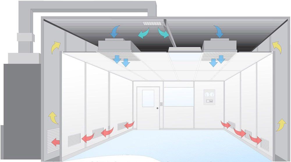
The clean ICU purification air conditioning is a large energy consumer. In order to save energy, the clean ICU has different purification levels of working states, which can be reasonably selected according to the specific usage. The purification level of the clean ICU control panel is set as follows: high purification, low purification, and duty operation (the fan purification unit of each bed is also set as high purification, medium purification, and low purification).
High purification: When the "high purification" indicator light is on, the fan runs at full speed, and the room reaches the highest purification level and maximum temperature regulation effect. That is, the ICU ward purification system is in a "high purification level state" and can reach the purification level designed for the clean ICU ward.
Low purification: When the "low purification" indicator light is on, the fan runs at a low speed, the room maintains cleanliness and appropriate temperature, and the clean 1CU ward is in a "low purification level state", which cannot reach the purification level designed for the clean ICU ward. For example, if the design level of the 10,000-level ICU ward is 10,000, it cannot reach the 10,000-level purification standard when the low purification level is selected.
Duty operation: The clean ICU ward maintains a certain positive pressure to ensure that the room is not polluted by the outside world. The clean ICU and some auxiliary rooms use independent local purification units to achieve the effect of purifying the air. There are also three switches of "high purification", "medium purification" and "low purification", which are equivalent to the three operating states of high purification, low purification and duty operation on the control panel.
In short, whether it is a clean ICU ward or an auxiliary room, in order to save energy, different purification fan operating states can be selected according to the specific situation. For the clean ICU ward used every day, it is best not to stop the machine. The corresponding purification system only switches between "high-level purification state" and "low-level purification state" and "duty state".
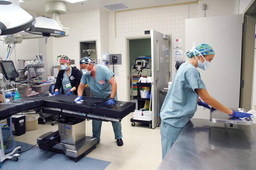
1.2 Temperature selection
Each clean ICU ward and each bed in the hall is equipped with a temperature setting switch, that is, a temperature controller, which can be used to select the desired room temperature through its temperature control knob. It is recommended to set it between 22 and 25℃.
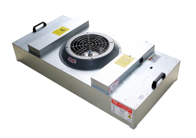
1.3 Purification air conditioning fan unit
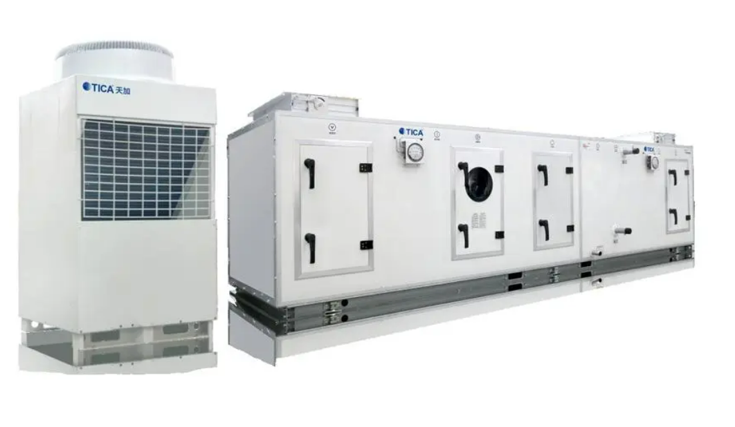
The fan is the focus of the inspection, mainly to see whether the belt is waxed or dropped. The belt between the active wheel and the passive wheel can be pressed by hand, and the pressure should be 1.25-2.5cm. If the belt is too loose, the Air volume will decrease. If it is too tight, it is easy to damage the bearing seat. In addition, the bearing should be oiled on time.
1.4 Motor
The insulation of the motor should be checked regularly.
1.5 Filter
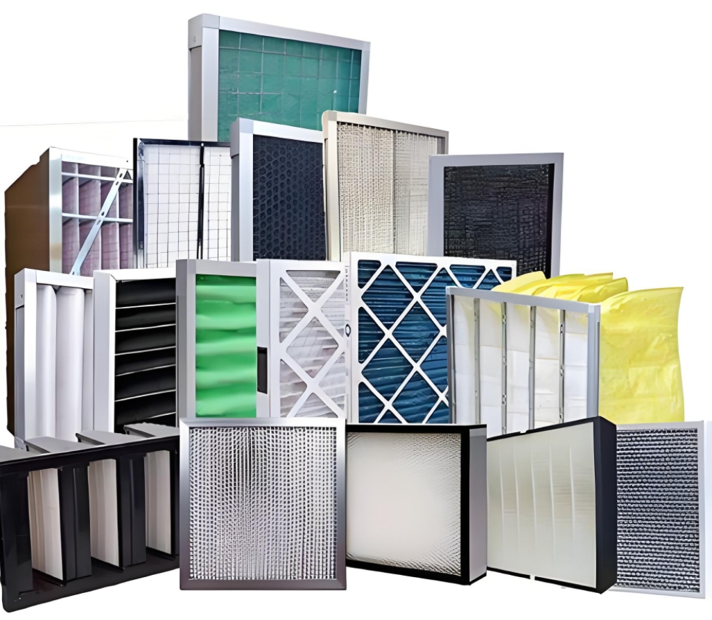
The Air Filter is the core equipment of the air conditioning purification system. If the filter is overloaded (high dust holding capacity) and even its back has been penetrated by dust, it will be dusty when touched by hand. If this filter continues to be used, it will not only fail to remove dust, but it will also become a new dust source. That is, the transmission situation is not as serious as the above, but the dust holding capacity is too much, the positive force is too high, the air volume is reduced, or it is partially penetrated, and the seat is blown over. Therefore, these can only be avoided if you learn the appropriate use cycle. During operation, the resistance should be checked regularly to determine when to replace the air filter.
| Filter Type | Application/Location | Recommended Replacement Cycle | Factors Affecting Cycle | monitoring/Indicators |
|---|---|---|---|---|
| HEPA Filter (Pre-filter) | Inlet or pre-filter stage before HEPA | 3 to 6 months | - Airborne particle levels - Filter loading - Room usage intensity | - Pressure drop across the filter - Visual inspection of filter condition |
| HEPA Filter (Main filter) | Main filtration for critical areas (ICU) | 12 to 24 months | - Airborne contamination level - Environmental pollutants | - Particle count monitoring - Pressure differential across the filter |
| Activated Carbon Filter | For VOCs (volatile organic compounds) and odors | 6 to 12 months | - Presence of VOCs - Chemical pollutants in the air | - VOC sensor readings - Carbon filter capacity testing |
| Medium Efficiency Filter | For larger particles (dust, lint) | 6 to 12 months | - Air quality monitoring - Filter contamination rate | - Pressure drop - Visual inspection (e.g., discoloration, dirt buildup) |
| ULPA Filter | For ultra-low particle environments | 18 to 24 months | - Environmental conditions (e.g., air quality) - High-containment applications | - Particle count measurements - Pressure drop readings |
| Pre-filter for AC Systems | In the HVAC system (before HEPA) | 3 to 6 months | - Dust accumulation rate - HVAC system air flow rate | - air flow testing - Visual inspection of accumulation |
| Exhaust/Decontamination Filter | In exhaust systems (post-ICU) | 6 to 12 months | - High contamination in air exhaust - Airborne pathogens or chemicals | - Pressure differential - Particle and microbial testing in exhaust air |
1.6 Air conditioning water pipe
The air conditioning water pipe should be repaired every year and the filter should be cleaned frequently, and the damaged insulation material should be replaced and repaired. The air conditioning circulating water and make-up water must be treated.
1.7 Humidifier
Some metal impurities and scale will accumulate in the water tray under the humidifier. These dirt should be removed regularly to ensure the normal operation of the humidifier and avoid pollution. The water baffle should be cleaned frequently, and the drainage point of condensed water should be checked and removed. These places are hotbeds for bacteria.
1.8 Air conditioning control cabinet
There is an air conditioning control cabinet on the equipment floor. Each control cabinet has an operation and fault display light. It should be inspected every day and any fault should be eliminated in time. Check the contactor and intermediate relay in the cabinet every month and repair according to the control cabinet drawing.
1.9 Distribution box
The distribution box on the wall in the ICU is equipped with a main switch and an electrical socket box, a switch panel, an equipment belt, and a lighting switch. When a certain power supply fails, the branch switch can be immediately turned off to ensure the power supply of other power supply circuits. When a distribution box trips, the problematic branch switch can be disconnected first, then the reset button of the main switch can be pressed, and then the main switch can be closed to supply power. If normal power supply cannot be restored, the maintenance department should be notified immediately for inspection.
2. ICU cleanliness and bacterial concentration test
2.1 Before the clean ICU ward is tested, the system should have been running statically for 60 minutes. After confirming that there are no obvious problems in the detection of Wind speed, Ventilation frequency and static pressure difference, the dust concentration is tested again.
2.2 When the air supply and inlet are arranged centrally, the operating area and the surrounding area should be tested separately. The number and location of the measuring points should comply with the provisions of the technical specifications of the hospital clean operating department building; when there are significant obstacles nearby, they can be avoided appropriately. When the air outlets are dispersed, the whole room shall be uniformly distributed for testing. The measuring points can be evenly distributed, but should not be arranged directly below the air outlets.
2.3 The measuring points shall be arranged on a plane 0.8 m above the ground.
2.4 The number of testing personnel shall not exceed 2. They shall all wear clean work clothes and be in the downwind position of the measuring point. They shall move as little as possible. The culture dishes shall be placed from the inside to the outside and collected from the outside to the inside to avoid inaccurate measurements caused by human contamination.
2.5 The bacterial concentration should be measured after the other items are tested and the whole room surface is routinely disinfected. The surface bacterial density is a monitoring item. It shall be tested according to the method of GB15982 of the Hospital Disinfection and Hygiene Standards. The test results shall comply with the provisions of the technical specifications for the construction of clean operating rooms in hospitals.
2.6 When the sedimentation method is used to determine the concentration of sedimentation bacteria, the number of bacterial concentration measurement points shall not be less than the number of dust concentration measurement points in the measured area, and shall meet the requirements of the minimum number of culture III (excluding control dishes). The sampling time for each time shall not exceed 30 min.
2.7 Regardless of the method used to detect bacterial concentration, there must be two blank controls. The first time is to conduct a comparative test on the culture dish or culture medium strip used for testing, with one control dish per batch. The second time is when testing, with one control dish per room or area, to conduct a control test on the operation process: simulate the operation process, but the culture dish or culture medium strip should be immediately sealed after opening. Both control results must be negative. The entire operation should meet the requirements of aseptic operation.
2.8 After sampling, the culture medium strip or culture dish should be immediately placed at 37'E for 24 hours, and then the number of colonies grown should be counted. The average value of the colony count is rounded to Nd. 1 digit after the digit.
 +86 18186671616
 Jason@cleanroomequips.com
 MENU
MENU

