+86 13638632902
 Jason@cleanroomequips.com
 MENU
MENU

Introduction
The success of any cleanroom operation hinges on precise control of airborne particulate contamination, and the foundation of this control lies in understanding cleanroom airflow patterns. These patterns determine how air moves through the controlled environment, directly impacting contamination removal efficiency and overall cleanroom performance.
Different types of cleanroom airflow patterns serve distinct purposes and are suited for specific cleanliness requirements and applications. Making an informed decision about which pattern to implement requires thorough knowledge of their principles, advantages, and limitations. This comprehensive guide will explore the three primary categories of cleanroom airflow patterns in detail.
Readers will learn to identify different cleanroom airflow patterns, understand their working mechanisms, and apply this knowledge to select the most appropriate pattern for their specific requirements. This understanding is crucial for optimizing both performance and operational costs.
Part 1: Cleanroom Airflow Patterns Overview
Understanding cleanroom airflow patterns begins with recognizing their fundamental purpose in contamination control. These patterns are specifically engineered to manage how air moves within the controlled environment, directly impacting particle concentration and distribution.
The selection of appropriate cleanroom airflow patterns is critical because it affects not only cleanliness levels but also energy consumption, operational costs, and process compatibility. Different cleanroom airflow patterns offer varying levels of protection against particulate contamination.
1.1 What are Cleanroom Airflow Patterns?
Definition: Cleanroom airflow patterns refer to the organized movement and directional control of air within A CleanRoom environment. These patterns are deliberately designed to guide clean air across critical areas, dilute contaminants, and rapidly remove generated particles from the space.
The core objectives include providing a continuous supply of filtered air, establishing predictable air movement paths, and ensuring efficient contaminant removal. Properly designed cleanroom airflow patterns create a protective environment for sensitive processes and products.
1.2 Importance of Airflow Pattern Selection
The choice of cleanroom airflow patterns directly impacts several critical factors:
- Cleanliness Level: Determines the achievable ISO classification
- Energy Consumption: Different patterns require varying fan power and HVAC capacity
- Capital and Operational Costs: Installation expenses and ongoing maintenance requirements
- Process Compatibility: Suitability for specific manufacturing or research activities
- Flexibility and Scalability: Ability to adapt to changing requirements
For example, a pharmaceutical company might achieve iso 5 classification using vertical unidirectional flow at an air velocity of 0.45 m/s ±20%, while an Electronics assembly facility might use non-unidirectional flow with 40-60 air changes per hour to maintain ISO 7 conditions at a significantly lower cost.
Part 2: Unidirectional Airflow (Laminar Flow)
Unidirectional airflow represents the gold standard in cleanroom airflow patterns for applications requiring the highest levels of contamination control. This pattern creates a predictable, consistent movement of air that efficiently sweeps particles away from critical areas.
The implementation of unidirectional cleanroom airflow patterns requires careful engineering and significant investment but delivers unparalleled protection for sensitive processes. These patterns are characterized by their straight, parallel streamlines with minimal cross-contamination between adjacent airstreams.
2.1 Principles and Characteristics
Unidirectional airflow operates on the principle of moving air in a single direction with uniform velocity across the entire cross-section of the cleanroom or designated area. Air typically moves either vertically (from ceiling to floor) or horizontally (from one wall to the opposite wall), acting like a "piston" that pushes contaminants toward exhaust locations.
Laminar Flow Principle Diagram
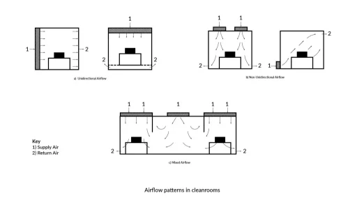
Figure 2: Unidirectional airflow principle showing particle removal mechanism
Advantages:
- Superior contamination control efficiency (typically 99.99%+ for particles ≥0.3μm)
- Predictable airflow paths with minimal turbulence
- Suitable for the highest cleanliness requirements (ISO 1-5)
- Rapid recovery from contamination events
Disadvantages:
- High capital investment (typically 30-50% more than non-unidirectional systems)
- Substantial energy consumption (fans must overcome filter resistance)
- Limited flexibility for layout changes
- Higher operational and maintenance costs
2.2 Vertical Unidirectional Flow
Operating Mechanism: Air enters through HEPA or ULPA filters covering 80-100% of the ceiling surface and exits through perforated floor tiles or low-level return air grilles. The downward movement creates a protective "curtain" of clean air that carries particles away from critical processes.
Vertical Laminar Flow Cleanroom Diagram
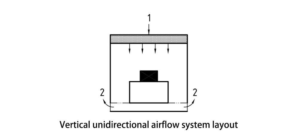
Figure 3: Vertical unidirectional airflow system layout
Application Examples:
- ISO 1-5 classified environments
- Semiconductor manufacturing (photolithography areas)
- Pharmaceutical sterile filling operations (Grade A/B areas)
- Biotechnology research laboratories
- Medical device assembly for implantable devices
Technical Specifications: Typical airflow velocity ranges from 0.3 to 0.5 m/s (60-100 fpm) with variations of no more than ±20% across the entire cross-section. Deiiang™ engineers like Jason.peng recommend maintaining these velocities within strict tolerances to ensure consistent performance.
2.3 Horizontal Unidirectional Flow
Operating Mechanism: Filtered air enters from one wall covered with HEPA/ULPA filters and moves horizontally across the room to exhaust grilles on the opposite wall. This creates a clean "sweeping" action that carries contaminants away from the critical zone.
Horizontal Laminar Flow Cleanroom Diagram
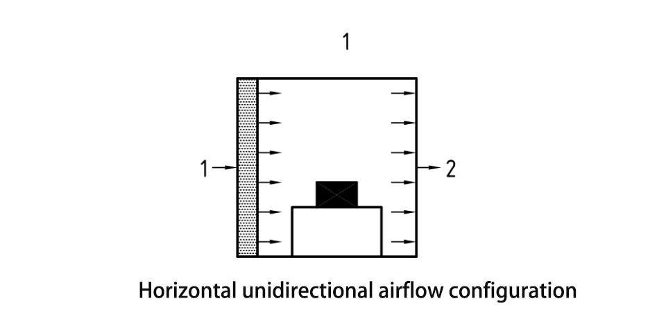
Figure 4: Horizontal unidirectional airflow configuration
Application Examples:
- iso 5 environments or higher cleanliness requirements
- modular cleanrooms and standalone workstations
- air showers and gowning rooms
- Specific electronic assembly processes
- Laboratory weighing stations and sampling areas
Considerations: Horizontal flow systems typically require more careful operator positioning since contamination can be carried from upstream to downstream processes. Deiiang™ designs by Jason.peng often incorporate strategic workstation placement to minimize this risk.
Part 3: Non-Unidirectional Airflow (Turbulent/Mixed Flow)
Non-unidirectional cleanroom airflow patterns utilize a different approach to contamination control, relying on dilution and mixing rather than directional sweeping. These patterns are characterized by more random air movement with varying velocities and directions.
The design of non-unidirectional cleanroom airflow patterns focuses on achieving sufficient air changes to maintain target cleanliness levels while optimizing energy efficiency. These systems represent a cost-effective solution for many industrial applications with moderate cleanliness requirements.
3.1 Principles and Characteristics
Non-unidirectional airflow operates through the principle of dilution, where filtered air is introduced at multiple points to mix with and gradually reduce contaminant concentrations. Unlike unidirectional flow, air movement follows less predictable paths with eddies and recirculation zones.
Turbulent Flow Principle Diagram
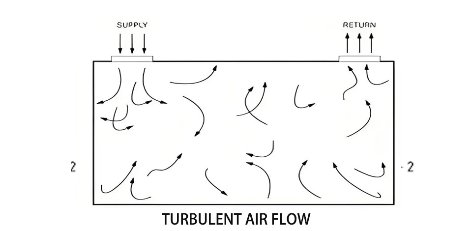
Figure 5: Non-unidirectional airflow mixing pattern
Advantages:
- Lower capital investment (typically 40-60% of unidirectional systems)
- Reduced energy consumption (lower pressure drops across filters)
- Greater flexibility in equipment layout and process changes
- Easier integration with existing building infrastructure
Disadvantages:
- Lower contamination control efficiency (potential for dead zones)
- Slower recovery from contamination events
- Limited to moderate cleanliness requirements (ISO 6-8 typically)
- More challenging to validate and maintain consistent conditions
3.2 Operating Mechanism and Air Distribution
Air typically enters through ceiling-mounted diffusers or filter modules and returns through low-level grilles located on walls or occasionally in the floor. The system relies on high air change rates (ACH) to dilute contaminants to acceptable levels.
Turbulent Flow Cleanroom Diagram
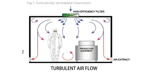
Figure 6: Non-unidirectional airflow system with supply and return locations
Air Change Calculation Example: For an ISO 7 Cleanroom with dimensions 10m × 8m × 3m (240m³ volume) requiring 60 ACH:
Required airflow = Room volume × ACH = 240m³ × 60h⁻¹ = 14,400m³/h
This translates to approximately 8,472 CFM (14,400 × 35.315 ÷ 60)
Deiiang™ specialists like Jason.peng use such calculations to properly size HVAC systems for non-unidirectional cleanroom airflow patterns.
3.3 Application Scenarios
Non-unidirectional flow is suitable for:
- ISO 6-8 classified environments
- General electronics assembly and testing
- Medical device packaging and secondary operations
- Pharmaceutical compounding and non-sterile manufacturing
- Food processing in controlled environments
- Research laboratories with moderate cleanliness requirements
For instance, a Deiiang™ project for an automotive electronics manufacturer utilized non-unidirectional flow with 45 ACH to maintain ISO 7 conditions while reducing energy costs by 35% compared to a unidirectional alternative.
Part 4: Mixed Flow & Localized Unidirectional Flow
Mixed flow cleanroom airflow patterns represent a hybrid approach that combines the benefits of both unidirectional and non-unidirectional systems. This strategy optimizes both performance and cost by applying higher-level protection only where needed.
The implementation of mixed cleanroom airflow patterns requires careful zoning and interface management to ensure proper pressure cascades and minimize cross-contamination between areas with different airflow characteristics.
4.1 Mixed Flow Systems
Concept: Mixed flow integrates unidirectional protection within specific areas of a predominantly non-unidirectional cleanroom. Common implementations include installing Fan Filter Units (FFUs) or laminar flow canopies over critical processes while maintaining general dilution airflow throughout the remainder of the space.
Mixed Flow Cleanroom Diagram
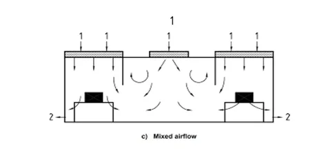
Figure 7: Mixed airflow pattern with localized protection
Advantages:
- Cost-effective solution (targeted high-level protection)
- Energy efficiency (unidirectional flow only where needed)
- Flexibility to reconfigure critical zones as processes change
- Scalable approach that can evolve with operational needs
Implementation Example: A pharmaceutical packaging line might use iso 8 background environment with ISO 5 unidirectional flow modules over filling and capping stations, achieving a 40% cost savings compared to a full ISO 5 unidirectional cleanroom.
4.2 Localized Unidirectional Flow Devices
Several specialized devices create localized unidirectional environments within larger cleanrooms:
FFU (Fan Filter Unit)
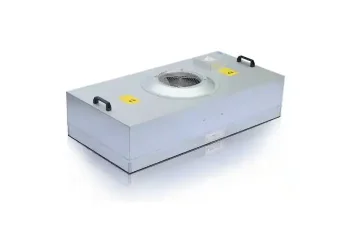
Self-contained modules with integrated fan and HEPA/ULPA filters that can be mounted in grid systems to create customizable unidirectional zones. Deiiang™ offers FFUs with variable speed control for optimal energy management.
Laminar Flow Hoods/Benches
Enclosed or semi-enclosed workstations that provide ISO 5 or better conditions for specific processes. These are ideal for laboratory work, sample preparation, or small-scale assembly operations.
Isolators & RABS
Fully enclosed systems with integrated unidirectional airflow that provide complete physical separation between the process and operators. These offer the highest level of protection for sterile processes.
Jason.peng, Senior Product Designer at Deiiang™, emphasizes that "proper integration of localized devices requires careful consideration of interface dynamics, including pressure relationships and airflow interactions with the surrounding environment."
Part 5: Airflow Pattern Comparison Analysis
Selecting the appropriate cleanroom airflow patterns requires careful evaluation of multiple factors. The following comparison table provides a comprehensive overview of the key characteristics of each airflow pattern type.
| Parameter | Unidirectional Flow | Non-unidirectional Flow | Mixed Flow |
|---|---|---|---|
| Cleanliness Level | ISO 1-5 | ISO 6-8 | ISO 5 (local) + ISO 6-8 (background) |
| Airflow Direction | Parallel, single direction | Mixed, turbulent | Combination of both |
| Air Velocity | 0.3-0.5 m/s (guideline) | Variable, not specified | 0.3-0.5 m/s (local), variable (background) |
| air changes per hour | Not applicable (continuous flow) | 20-100+ (depending on ISO class) | Background: 20-60, Local: continuous |
| Contamination Control | Excellent (sweeping action) | Good (dilution principle) | Excellent (local), Good (background) |
| Construction Cost | High | Moderate | Moderate to High |
| Operational Cost | High | Moderate | Moderate |
| Energy Consumption | High | Moderate | Moderate to High |
| Typical Applications | Pharmaceutical sterile filling, Microelectronics | Medical device assembly, Packaging | Pharmaceutical non-sterile, Electronics assembly |
This comparison of different types of cleanroom airflow patterns demonstrates that there is no universally superior option—the optimal choice depends on specific operational requirements, budget constraints, and performance expectations.
Part 6: Key Factors for Choosing Airflow Patterns
Selecting the most appropriate cleanroom airflow patterns requires a systematic approach that considers multiple technical, operational, and economic factors. This decision significantly impacts both performance and lifecycle costs.
The evaluation of Cleanroom airflow designs should begin with a thorough assessment of process requirements and progress through consideration of constraints and optimization opportunities. Deiiang™ employs a structured methodology to guide this selection process.
6.1 Required Cleanliness Level
The target ISO classification is typically the primary determinant in selecting cleanroom airflow patterns. Each ISO class has recommended or required airflow approaches:
- ISO 1-3: Always requires unidirectional flow
- ISO 4-5: Typically uses unidirectional flow
- ISO 6-7: Can use either non-unidirectional or mixed flow
- ISO 8-9: Typically uses non-unidirectional flow
It's important to note that some regulatory standards (such as EU GMP) may mandate specific airflow approaches regardless of achieved particulate counts.
6.2 Process Requirements and Contamination Sources
The nature of operations conducted in the cleanroom significantly influences airflow pattern selection:
- Particle Generation: High particle-generating processes may require unidirectional flow for effective containment
- Heat Load: Processes with significant heat emission may benefit from non-unidirectional flow for better mixing
- Operator Presence: Areas with frequent personnel movement may need carefully directed airflow to protect critical zones
- Material Flow: The movement of materials and equipment should be coordinated with airflow directions
6.3 Budget Constraints
Financial considerations play a crucial role in selecting cleanroom airflow patterns:
- Capital Investment: Unidirectional systems typically cost 1.5-2x more than non-unidirectional systems of equivalent size
- Operational Costs: Energy consumption for unidirectional flow can be 40-60% higher due to greater filter pressure drops
- Maintenance Expenses: Filter replacement costs are typically higher for unidirectional systems due to larger filter areas
6.4 Spatial Constraints and Layout
Physical limitations can influence the feasibility of different cleanroom airflow designs:
- Ceiling Height: Vertical unidirectional flow requires sufficient plenum space above the filters
- Equipment Placement: Large equipment can disrupt airflow patterns and create dead zones
- Room Dimensions: Aspect ratios may favor horizontal versus vertical flow configurations
- Structural Limitations: Floor loading capacity may limit options for raised floor systems
6.5 Energy Efficiency Requirements
Sustainability considerations are increasingly important in Cleanroom design:
- Variable Air Volume (VAV) Systems: Can reduce energy use in non-unidirectional systems
- FFU Technology: Modern FFUs with EC motors offer significant energy savings
- Heat Recovery: Can be incorporated into any airflow pattern to improve efficiency
- Lighting and Process Loads: Affect HVAC sizing regardless of airflow pattern
Jason.peng from Deiiang™ notes that "the most successful projects result from early collaboration between cleanroom designers, process engineers, and facilities personnel to align airflow strategy with operational needs and constraints."
Part 7: Airflow Pattern Verification & Optimization
Once cleanroom airflow patterns are implemented, rigorous verification is essential to ensure they perform as designed. This process confirms that the installed system meets specified requirements and identifies opportunities for optimization.
Regular assessment of cleanroom airflow patterns helps maintain consistent performance over time and can reveal developing issues before they impact product quality or process yield. Deiiang™ recommends establishing a comprehensive monitoring and maintenance program.
7.1 Verification Methods
Several standardized methods are used to verify cleanroom airflow patterns:
air velocity testing: Measures airflow speed at multiple locations to ensure uniformity and compliance with design specifications. For unidirectional flow, measurements are typically taken 150-300mm below the filter face.
Airflow Visualization (Smoke Testing): Uses artificial smoke or mist to visually demonstrate airflow directions, identify turbulence zones, and detect potential dead spots. This method provides immediate, intuitive understanding of airflow behavior.
Smoke Test Visualization
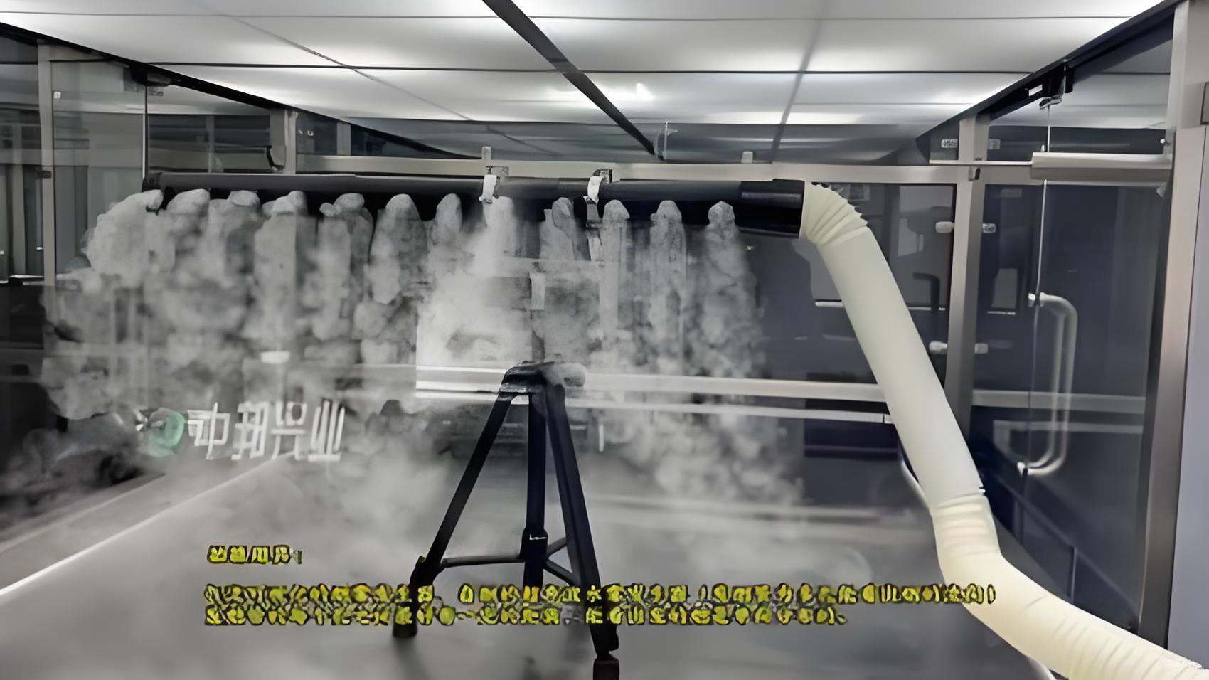
Figure 9: Smoke test demonstrating airflow patterns in a cleanroom
Particle Counting: The ultimate verification method that measures airborne particle concentrations to confirm compliance with target ISO classification. This testing should be performed under as-built, at-rest, and operational conditions.
Pressure Differential Measurement: Verifies that proper pressure cascades are maintained between adjacent areas to prevent cross-contamination. Typical differentials range from 10-15 Pa between successively cleaner zones.
7.2 Computational Fluid Dynamics (CFD) Simulation
CFD provides powerful analytical capabilities for predicting, analyzing, and optimizing cleanroom airflow patterns before construction. This technology creates virtual models that simulate airflow behavior under various conditions.
CFD Simulation Analysis
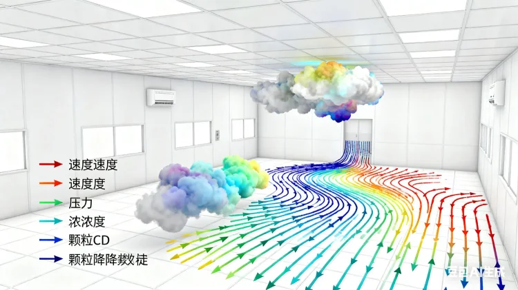
Figure 10: CFD analysis of cleanroom airflow patterns and contamination control
CFD Applications:
- Predicting airflow patterns under different design scenarios
- Identifying potential turbulence zones and dead spots
- Optimizing equipment placement to minimize disruption
- Evaluating contamination dispersion from specific sources
- Assessing the impact of personnel movement
Deiiang™ utilizes advanced CFD modeling to optimize cleanroom airflow designs for clients, typically achieving 15-25% improvement in airflow efficiency compared to conventional design approaches.
7.3 Optimization Strategies
Based on verification results, several optimization approaches can improve cleanroom airflow pattern performance:
- Supply/Return Adjustment: Modifying the location or configuration of supply diffusers and return grilles
- Equipment Reconfiguration: Repositioning process equipment to minimize airflow disruption
- Operational Procedures: Implementing personnel protocols that complement airflow patterns
- Control System Tuning: Adjusting pressure differentials and airflow volumes for optimal performance
- Retrofit Solutions: Adding flow guidance devices or local extraction where needed
Regular re-verification (typically annually or after significant modifications) ensures that cleanroom airflow patterns continue to perform as intended throughout the facility lifecycle.
Conclusion
Cleanroom airflow patterns form the fundamental basis for contamination control in critical environments. The selection between unidirectional, non-unidirectional, and mixed flow approaches represents a strategic decision that balances performance requirements with economic considerations.
Understanding the principles, applications, and limitations of each cleanroom airflow pattern type enables informed decision-making that aligns with specific operational needs. There is no universally optimal solution—the best choice depends on a careful evaluation of cleanliness requirements, process characteristics, spatial constraints, and budget limitations.
It is crucial to recognize that cleanroom airflow patterns are not static installations but dynamic systems that require ongoing verification, monitoring, and occasional optimization. Changes in processes, equipment, or operational practices may necessitate adjustments to maintain optimal performance.
Call to Action
Ready to optimize your cleanroom airflow patterns? The Deiiang™ team, led by experienced professionals like Jason.peng, offers comprehensive cleanroom design services, airflow pattern analysis, and optimization solutions tailored to your specific requirements.
Contact us today for a consultation on your cleanroom airflow design challenges or to request our technical guide on selecting and optimizing cleanroom airflow patterns for various applications.
Appendix
Glossary of Terms
- ACH (Air Changes Per Hour): The number of times the entire air volume in a room is replaced per hour
- HEPA (High Efficiency Particulate Air) Filter: Filter capable of removing at least 99.97% of particles ≥0.3μm
- ULPA (Ultra Low Penetration Air) Filter: Filter capable of removing at least 99.999% of particles ≥0.12μm
- FFU (Fan Filter Unit): Self-contained module with fan and HEPA/ULPA filter for creating localized clean zones
- CFD (Computational Fluid Dynamics): Computer-based simulation of fluid flow and related phenomena
Frequently Asked Questions
Q: How can I determine which cleanroom airflow pattern my facility uses?
A: The simplest method is visual observation of airflow direction and supply/return locations. Unidirectional flow typically features full ceiling filters with floor returns, while non-unidirectional flow uses ceiling diffusers with wall returns. Smoke testing provides definitive verification.
Q: What is the typical airflow velocity for unidirectional cleanrooms?
A: Standard guidance suggests 0.45 m/s (90 fpm) ±20% for vertical unidirectional flow. However, specific requirements may vary based on application, with some modern facilities successfully operating at lower velocities (0.3-0.35 m/s) with proper design.
Q: Can equipment placement affect cleanroom airflow patterns?
A: Yes, significantly. Large equipment can create turbulence, dead zones, or airflow bypass that compromises contamination control. CFD analysis during design phase and smoke testing after installation help identify and mitigate these issues.