+86 13638632902
 Jason@cleanroomequips.com


 MENU
MENU
From "particle concentration compliance" to "system performance compliance" — that shift defines modern cleanroom engineering. iso class 5–8 cleanrooms are widely used in semiconductors, electronics manufacturing, pharmaceuticals, medical devices, laboratories, food processing, and precision manufacturing.
Passing a particle count test depends on far more than the number of ffus. Supply and return air organization, equipment heat loads, personnel activity, process layout, and enclosure airtightness all play decisive roles.
Key insight: iso 14644-1 defines airborne particle cleanliness classes. FFU spacing and coverage must be determined by cleanliness grade, contamination load, room geometry, return-air paths, and validated test results — not by a fixed rule of thumb.
This article explains how to translate ISO 14644-1 classification requirements into executable FFU layout design, airflow uniformity strategies, testing protocols, and project delivery plans.
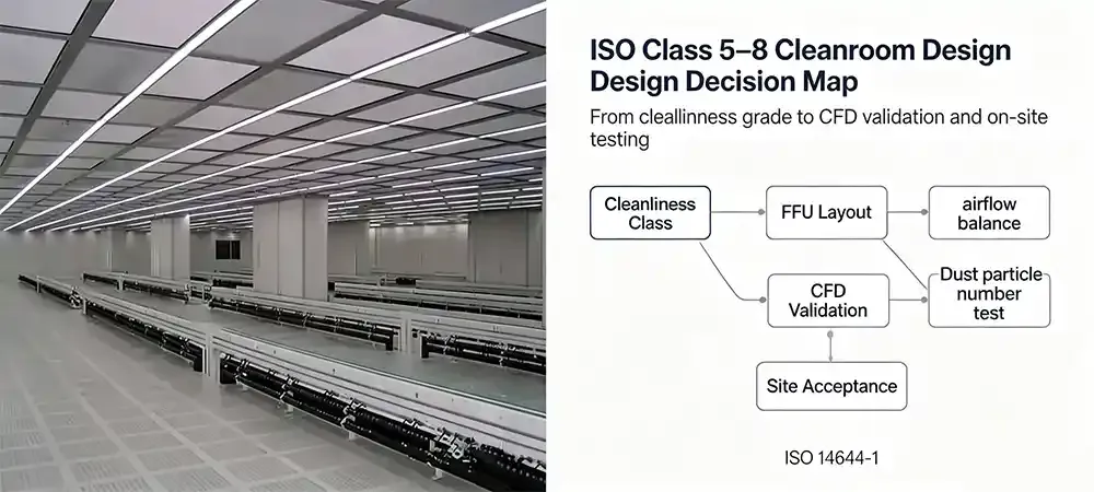
ISO Class 5–8 cleanroom design Decision Map — from cleanliness grade to CFD validation and on-site testing.
What Does ISO 14644-1:2015 Actually Require?
Understanding the scope of ISO 14644-1 is the first step toward a compliant FFU layout design. The standard classifies cleanrooms by airborne particle concentration but does not dictate equipment selection or placement.
Scope of ISO 14644-1:2015
- Classifies cleanrooms and clean zones by airborne particle concentration.
- Specifies sampling point locations and data evaluation methods for classification.
- Supports verification under as-built, at-rest, and operational states.
- Does not prescribe FFU brand, quantity, ceiling coverage, air-change rate, or fixed face velocity.
Critical boundary: The standard requires particle concentration limits, sampling, and classification. fan filter unit spacing, airflow volume, and pressure differentials are engineering design parameters that must be validated through on-site testing.
Maximum Particle Concentration Limits for ISO Classes 5–8
The table below shows the maximum allowable particle concentrations for ISO Class 5 through Class 8 at common particle sizes. These limits form the foundation of any cleanroom dead zones risk assessment.
| ISO Class | ≥0.1 μm | ≥0.3 μm | ≥0.5 μm | ≥1.0 μm | ≥5.0 μm |
|---|---|---|---|---|---|
| iso 5 | Verify per standard | Verify per standard | 3,520 /m³ | 832 /m³ | Not recommended |
| ISO 6 | Verify per standard | Verify per standard | 35,200 /m³ | 8,320 /m³ | 293 /m³ |
| ISO 7 | — | — | 352,000 /m³ | 83,200 /m³ | 2,930 /m³ |
| iso 8 | — | — | 3,520,000 /m³ | 832,000 /m³ | 29,300 /m³ |
* Verify with authorized ISO 14644-1:2015 text for full particle size ranges and application notes.
As-Built, At-Rest and Operational Conditions
- As-built: Facility complete, production equipment, materials, and personnel not yet installed.
- At-rest: Equipment installed and operating per agreement, but no operators present.
- Operational: Facility running under specified conditions with agreed number of personnel.
The same room can yield significantly different particle counts across these states. Your FFU layout design must target the final acceptance state.
ISO Classification Is Not the Same as Complete Cleanroom Qualification
Beyond ISO 14644-1 particle classification, projects often require additional testing:
- Airflow volume and velocity
- HEPA/ULPA filter integrity
- Room pressure differential
- Airflow direction and smoke visualization
- Temperature and humidity
- Recovery time
- Noise, illumination, and other client-specific items
ISO classification defines the result a cleanroom must ACHieve. It does not dictate where fan filter units should be placed — that is an engineering decision based on process risk and airflow strategy.
How ISO Class 5–8 Changes the Cleanroom Design Strategy
Each ISO class imposes different priorities on FFU layout design. A strategy that works for ISO 8 will often fail for ISO 5, and over-designing an ISO 7 space wastes capital and energy.
Understanding these distinctions helps engineers balance airflow uniformity with project budget and operational flexibility.

ISO Class 5 Design Priorities
- Requires tighter contamination control, often with unidirectional or locally enhanced airflow.
- Critical process zones may need 100% coverage or high-density FFU arrays.
- Personnel, equipment, and material flow must align with airflow direction.
- Focus FFUs directly above process equipment, operator workstations, and exposed product areas.
Does ISO Class 5 require 100% FFU ceiling coverage? Not necessarily. The standard does not mandate a fixed coverage ratio. Full coverage depends on unidirectional flow requirements, process risk, and project specifications. Local ISO 5 zones can also be achieved with clean benches, laminar flow hoods, or mini-environments.
ISO Class 6 Design Priorities
- Balance cleanliness with energy consumption.
- Increase FFU density in critical zones; reduce density in non-critical areas.
- Avoid dead zones behind equipment, in corners, and along blocked return-air paths.
- Zoned control and EC fan speed regulation are highly effective.
iso class 7 Design Priorities
- Common in electronics assembly, pharmaceutical background areas, and medical device manufacturing.
- Typically uses non-unidirectional mixed flow, but effective dilution is still essential.
- Return-air grille placement is often as important as FFU count.
- Account for door openings, personnel density, and equipment heat dissipation.
iso class 8 Design Priorities
- Resist the temptation to reduce FFUs solely for cost savings.
- Focus on contamination source control, adequate ventilation, and pressure gradients.
- Large open areas need well-distributed return points to avoid long, uncontrolled return paths.
- Use local exhaust or mini-environment units for dust-generating equipment rather than increasing whole-room airflow.
Quick Selection Matrix for ISO Class 5–8
| Design Dimension | ISO 5 | ISO 6 | ISO 7 | ISO 8 |
|---|---|---|---|---|
| Primary Control Target | Critical product exposure | High-grade production | Dilution & pressure | Basic contamination control |
| Common Airflow Strategy | Unidirectional or local unidirectional | Mixed / locally enhanced | Non-unidirectional mixed | Non-unidirectional mixed |
| FFU Design Focus | Uniformity & critical-point protection | Zoned density | Supply-return coordination | Prevent large dead zones |
| Recommended Validation | CFD + smoke + particle | CFD or layout + testing | Air balance + particle | Airflow + pressure |
This matrix is an engineering guide, not an ISO 14644-1 requirement.
FFU Layout Design: From Required Airflow to Ceiling Arrangement
A systematic approach to FFU layout design starts with process risk and ends with validated airflow. The following six steps provide a repeatable framework for any ISO Class 5–8 project.
Proper fan filter unit spacing ensures that clean air reaches every critical surface without creating stagnant zones or wasteful overlap.
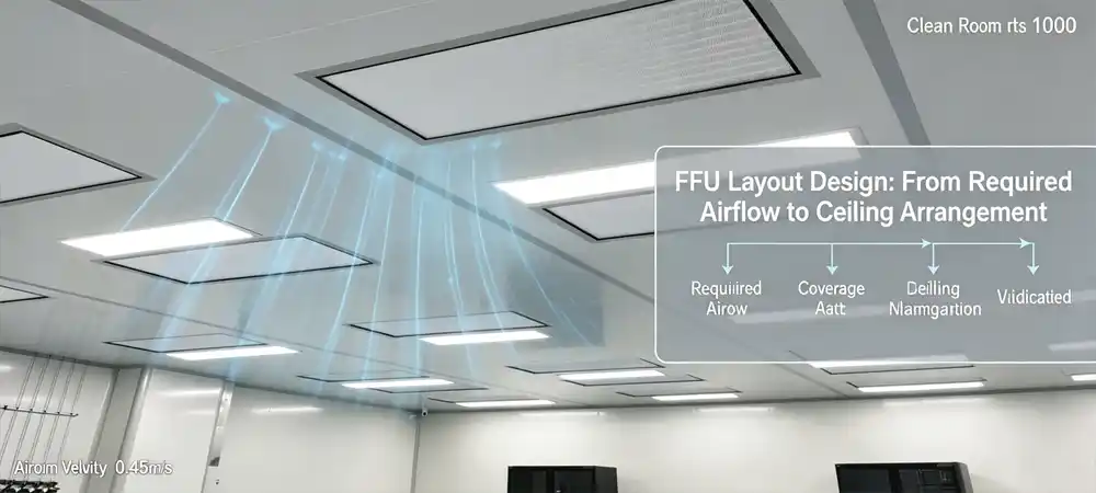
Step 1—Define the Process and Contamination Risks
Gather these inputs before placing a single FFU on the ceiling grid:
- Room length, width, height, and ceiling structure
- Target ISO class and acceptance state
- Production equipment dimensions and locations
- Personnel count, activity level, and gowning grade
- Equipment heat load and local exhaust volume
- Product open locations and critical height zones
- Doors, pass-throughs, air showers, and material flow routes
- Return-air chase, column, or low-level grille positions
Start from process risk, not from the ceiling grid. A cleanroom dead zones analysis begins with understanding where contamination matters most.
Step 2—Estimate Total Supply Airflow
Use the following formula for preliminary airflow estimation:
Required Supply Airflow = Room Volume × Target air changes per Hour
Q = V × ACH
Q = V × ACH
- ACH is a preliminary parameter, not a fixed ISO 14644-1 requirement.
- Adjust for contamination load, room state, return-air configuration, equipment exhaust, and recovery time.
- For unidirectional zones, use effective cross-sectional area and target average velocity instead of ACH:
Q = A × v × 3,600
Where Q = airflow (m³/h), A = effective supply area (m²), v = average velocity (m/s).
Step 3—Calculate the Preliminary FFU Quantity
Preliminary FFU Quantity = Required Total Airflow ÷ Effective Airflow per FFU
Use actual operating airflow, not the no-resistance or maximum-speed rating. Consider:
- HEPA/ULPA filter initial and final resistance
- FFU set speed and control method
- Ceiling static pressure and return-path resistance
- Voltage, control logic, design margin, and noise limits
Step 4—Convert FFU Quantity into a Ceiling Coverage Ratio
FFU Coverage Ratio = Total Active FFU Face Area ÷ Available cleanroom ceiling Area × 100%
Coverage ratio is a descriptive metric — it does not independently prove compliance. Calculate whole-room and local critical-zone coverage separately.
Step 5—Determine Fan Filter Unit Spacing
Fan filter unit spacing depends on multiple factors:
- FFU size and discharge dimensions
- Ceiling module and grid constraints
- Room clear height and airflow diffusion angle
- Target working-plane height
- Equipment height and thermal plumes
- Return-air grille locations
- Unidirectional flow requirements
- Lighting, sprinklers, and ceiling components between FFUs
A practical engineering approach:
- Establish an initial grid based on ceiling module.
- Prioritize FFUs directly above critical process zones.
- Check that adjacent FFU jets provide continuous coverage at working height.
- Adjust edge and equipment-overhead positions.
- Validate with CFD or smoke testing.
- Balance speeds based on measured velocity and particle data.
Step 6—Coordinate FFUs with Lighting, Sprinklers and Ceiling Systems
- Lighting fixtures disrupt continuous FFU arrays — coordinate early.
- Sprinkler heads can deflect or disturb downward airflow.
- Ceiling grid profiles may limit FFU sizes or orientations.
- Maintenance access routes reduce effective supply area.
- Fire, process, and control lines cross above the ceiling — reserve space.
- Ensure adequate clearance for filter replacement.
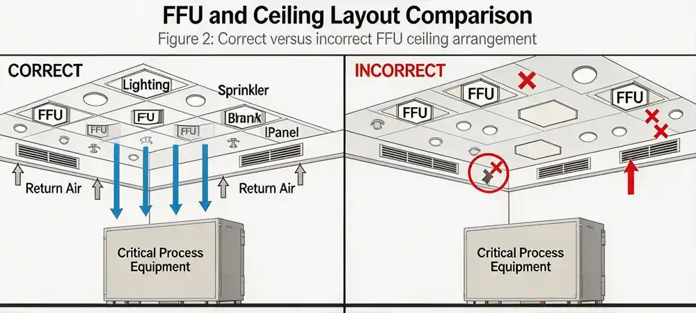
Correct vs incorrect FFU ceiling layout — showing FFUs, lighting, sprinklers, blank panels, return grilles, and critical process equipment.
What Causes Cleanroom Dead Zones?
Cleanroom dead zones are localized areas where airflow velocity drops below effective levels, particle removal is compromised, or recirculation occurs. They are not "no air" zones — they are zones where contamination control fails.
Definition of a Cleanroom Dead Zone
- Excessively low airflow velocity
- Poor contaminant removal efficiency
- Eddies or recirculation patterns
- Extended particle residence time
- Unstable temperature or pressure
- Locally elevated particle concentration relative to surrounding areas
Common Causes of Dead Zones
- Excessive fan filter unit spacing or discontinuous FFU arrays.
- Tall equipment blocking vertical airflow.
- Insufficient supply at corners and ceiling edges.
- Inadequate return-air grille area or poor placement.
- Return grilles blocked by equipment, racks, or stored materials.
- Frequent door openings causing pressure and airflow direction changes.
- Thermal plumes from high-heat process equipment.
- Imbalance between local exhaust and make-up air.
- Inconsistent FFU speed settings across the room.
- Filter resistance variation leading to uneven discharge.
Where Dead Zones Usually Appear
- Behind large equipment and cabinets
- Room corners and wall edges
- Under workbenches and tables
- Near doors and pass-throughs
- At the perimeter of FFU arrays
- Between tall storage racks
- Areas where return grilles are blocked
How to Detect Dead Zones
- CFD airflow simulation
- Velocity distribution mapping
- Smoke visualization tests
- Grid-based particle counting
- Recovery time testing
- Temperature and pressure trend logging
- On-site observation under operational conditions
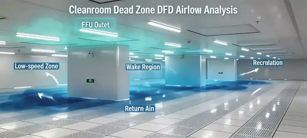
CFD velocity contour showing low-speed zones (blue) and wake regions behind equipment.
How to Improve Airflow Uniformity Without Overdesigning the System
Achieving airflow uniformity does not always require adding more FFUs. Often, smarter placement, return-path optimization, and zoned control deliver better results at lower cost.
Optimize FFU Distribution Instead of Simply Adding More Units
- Adding FFUs does not guarantee dead-zone elimination.
- Extra units in wrong locations can create interference and turbulence.
- Use differentiated placement — high density over critical zones, lower density over low-risk areas.
- Strengthen local protection rather than uniformly increasing whole-room airflow.
Improve the Supply and Return Air Relationship
- Supply from ceiling, return from low level — the standard cleanroom principle.
- Ensure adequate return-air grille area and even distribution.
- For long or large-span rooms, install multiple return points.
- Avoid "short-circuiting" — supply air should not flow directly to returns without passing through the work zone.
- Keep return paths clear of equipment and storage.
Use Zoned FFU Speed Control
Deiiang™ supports advanced control strategies that improve airflow uniformity while reducing energy use:
- Zone-based speed adjustment (critical production vs. non-critical areas)
- Production / standby mode switching
- Pressure differential interlock
- Filter resistance compensation
- Fault alarm and monitoring
- Energy consumption trend logging
Design note: Truly uniform airflow does not mean every FFU runs at the same speed. It means critical work zones receive stable, continuous, verifiable contaminant removal.
Manage Equipment Heat and Obstructions
- High-heat equipment creates thermal plumes that disrupt downward flow.
- Adjust FFU positions to compensate for heat sources.
- Install local high-efficiency supply over hot equipment.
- Optimize equipment exhaust and reduce surrounding obstructions.
- Use local laminar flow protection for critical process points.
Balance Airflow After Installation
- Measure each FFU's discharge airflow or average face velocity.
- Check filter installation and seal integrity.
- Adjust FFU speed settings.
- Balance supply, return, and exhaust across the room.
- Verify pressure gradients.
- Perform smoke and particle tests.
- Document final setpoints as the operational baseline.
Final check: A balanced system ensures that cleanroom dead zones are addressed before production begins.
Airflow Simulation and Validation Methods
CFD simulation is a powerful tool for predicting airflow uniformity and identifying potential cleanroom dead zones before construction begins. However, it does not replace on-site testing.
When Is CFD Simulation Necessary?
- ISO Class 5 or high-risk product exposure areas
- Irregular room geometries
- Dense equipment layouts with large obstructions
- Significant heat loads or multiple heat sources
- Multiple local exhaust systems
- Restricted return-air pathways
- Existing cleanroom upgrades or retrofits
- Client request to reduce FFU count or energy consumption
Inputs Required for a Reliable CFD Model
- Room 3D dimensions and ceiling geometry
- FFU positions and actual operating airflow
- Return-grille locations and boundary conditions
- Equipment sizes, positions, and heat outputs
- Personnel count and positions
- Process exhaust airflow rates
- Door opening conditions and schedules
- Temperature boundary conditions
- Target working-plane height
- Particle release points or contamination source assumptions
CFD Outputs That Should Be Reviewed
- Velocity contour maps
- Airflow streamlines and pathlines
- Pressure distribution
- Temperature contours
- Turbulence or recirculation zones
- Particle trajectories and residence time
- Working-plane uniformity index
- Contaminant migration during door opening events
CFD Does Not replace On-Site Testing
- CFD depends on input assumptions and model accuracy.
- Construction tolerances, filter resistance, and actual equipment operation can shift results.
- Final compliance must be confirmed through agreed on-site tests.
- Use CFD as a design tool, not as a substitute for validation.
Deiiang™ FFU Performance Data and Selection Guide
Deiiang™ offers a range of fan filter units designed for ISO Class 5–8 applications. All performance data is verified under standard test conditions.
Product designer Jason.peng and the Deiiang engineering team emphasize verifiable performance over nominal ratings.
Deiiang FFU Product Configuration
- Standard FFU dimensions: 1175×575 mm, 575×575 mm, and custom sizes
- Ceiling grid compatibility: T-grid, screw-in, or custom mounting
- Casing material: galvanized steel with powder coating or stainless steel
- Fan type: EC backward-curved centrifugal or AC forward-curved
- Motor: EC permanent magnet or AC induction
- Filter: HEPA H13/H14 or ULPA U15/U16/U17
- Filter efficiency: ≥99.99% @ 0.3 μm (HEPA) or ≥99.999% @ 0.12 μm (ULPA)
- Control: 0–10 V / Modbus / RS485 / network port
- Power: 220V 50Hz / 380V 3N 50Hz
- Optional: differential pressure sensor, temperature sensor, speed controller, and central monitoring
Verified Operating Data
| Model | Rated Airflow (m³/h) | External Static Pressure (Pa) | Power (W) | Noise dB(A) | Filter Grade | Control |
|---|---|---|---|---|---|---|
| DFF-1175 | 1800–2500 | 80–150 | 110–180 | 52–58 | H13/H14 | 0–10 V / Modbus |
| DFF-575 | 800–1200 | 60–120 | 65–95 | 48–54 | H13/H14 | 0–10 V / Modbus |
| DFF-ULPA | 1500–2200 | 100–180 | 130–210 | 54–60 | U15/U16/U17 | 0–10 V / Modbus |
Data measured with clean filter at rated voltage. Actual performance depends on system resistance and installation.
How Deiiang Selects an FFU for Different ISO Classes
- ISO Class 5 critical exposure: High-density FFU arrays with H14 or ULPA filters, zoned speed control, and redundant monitoring.
- ISO Class 6 precision assembly: Balanced H13 coverage with EC fan modulation and pressure interlock.
- iso class 7 general production: Cost-effective H13 FFUs with adequate return-air coordination.
- iso class 8 background area: Reliable H13 or H14 units with basic speed control and filter monitoring.
- Local mini-environment: Single or small arrays of high-efficiency FFUs over critical workstations.
- Existing cleanroom upgrade: Retrofit-compatible FFUs with improved EC efficiency and control integration.
Energy Consumption Example
Annual energy consumption can be estimated using this transparent model:
Annual Energy (kWh) = FFU Quantity × Average Input Power (W) × Operating Hours ÷ 1,000
Annual Cost = Annual Energy × Local Electricity Rate
For a 500 m² ISO 7 facility operating 6,000 hours/year:
- Fixed-speed FFU solution: 120 units × 160 W × 6,000 h = 115,200 kWh/year
- Deiiang EC FFU with zoned control: 120 units × 105 W (avg.) × 6,000 h = 75,600 kWh/year
- Estimated saving: ~34% reduction in FFU electricity consumption
Note: All savings figures are project-specific. Actual results depend on load profile, control strategy, and local electricity rates.
Deiiang™ Project Case Study—Eliminating Dead Zones in an ISO Class 6 Facility
This case study demonstrates how Deiiang™ applied systematic FFU layout design to eliminate cleanroom dead zones in an electronics manufacturing cleanroom.
Project Background
- Client industry: Precision electronics manufacturing
- Project location: Suzhou, China
- Cleanroom area: 450 m²
- Clear height: 3.2 m
- Target class: ISO Class 6 (at-rest)
- Operation: 2 shifts × 10 hours, 6 days/week
- Project type: New construction
- Delivery timeline: 10 weeks from concept to handover
Local User Persona and Scenario
Mr. Li, the facility manager, was responsible for an ISO Class 6 expansion. The project had to be completed within a fixed production shutdown window. Initial tests showed low-velocity recirculation zones behind large equipment and along room edges. Management required lower long-term electricity costs — simply adding more FFUs was not an option.
- Pass third-party ISO validation on schedule
- Eliminate dead zones near critical workstations
- Preserve existing ceiling and return-air structure
- Reduce initial FFU count or operating power
- Provide traceable testing and handover documentation
Initial Problems Found on Site
- Original FFU layout was a uniform grid — did not align with equipment positions.
- One side's low-level return grille was partially blocked by equipment.
- High-heat equipment generated thermal plumes that disrupted downward flow.
- Measured airflow varied significantly between adjacent FFUs.
- Pressure fluctuated when the main access door was opened.
- Critical working height (1.2 m) showed low-velocity zones.
Project Challenges
- Limited available ceiling area due to structural beams
- Large equipment obstructing airflow paths
- Short project window (8 weeks for installation + testing)
- Competing goals: validation and energy savings
Deiiang Diagnostic Process
- On-site dimension and equipment position verification.
- FFU and return-air grille airflow measurement.
- Grid-based particle concentration mapping at working height.
- Smoke visualization to confirm recirculation zones.
- CFD model built and validated against measured data.
- Scenario comparison: FFU count, spacing, and speed settings.
- Final layout selected to balance compliance and energy.
Deiiang's Specific Solution
- Moved from uniform grid to risk-based non-uniform layout.
- Increased local FFU density above critical product exposure zones.
- Relocated several FFUs from low-risk walkways to equipment wake zones.
- Adjusted and added low-level return-air paths.
- Implemented zoned speed control: critical zone @ higher speed, general area @ moderate, auxiliary @ low.
- Set production, standby, and night modes via control system.
- Completed filter leak testing, airflow balancing, pressure verification, and particle validation.
- Documented final FFU speed settings and test baseline.
Before-and-After Results
| Parameter | Before | After | Improvement |
|---|---|---|---|
| FFU quantity | 96 | 88 | −8 units |
| Working-plane avg velocity | 0.28 m/s | 0.33 m/s | +18% |
| Velocity uniformity (CV) | 32% | 18% | +44% |
| Max particle @ 0.5 μm | 28,000 /m³ | 12,000 /m³ | −57% |
| Room pressure differential | 12 Pa | 18 Pa | +50% |
| FFU system power (avg) | 14.2 kW | 10.8 kW | −24% |
| Annual estimated consumption | 85,200 kWh | 64,800 kWh | −24% |
| Validation result | Failed (local dead zones) | ISO 6 passed | — |
Lessons Learned
- Average FFU coverage cannot replace critical-zone analysis.
- Return-air path adjustment is sometimes more effective than adding FFUs.
- Operational-state equipment and personnel significantly change airflow patterns.
- Zoned speed control and balancing can reduce full-load operation while maintaining compliance.
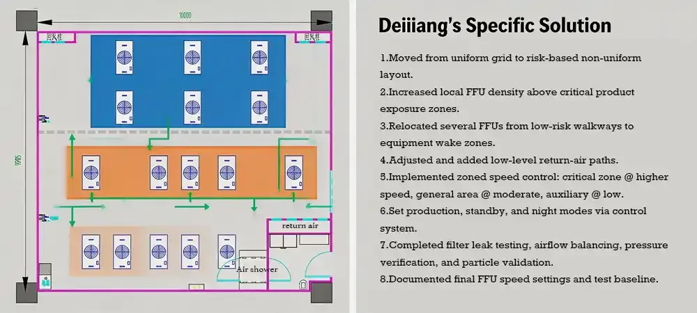
Deiiang ISO Class 6 cleanroom project — final FFU ceiling layout and installed units.
Cleanroom Project Cost, Schedule and Delivery Process
Understanding the cost drivers and delivery workflow helps project teams plan effectively for FFU layout design and installation.
What Determines the Project Cost?
- Room area and clear height
- Target ISO class and acceptance state
- FFU quantity and specifications (size, fan type, filter grade)
- HEPA or ULPA filter grade and quantity
- Ceiling and wall panel materials
- Return-air system complexity (chase, plenum, or ducted)
- Temperature and humidity control accuracy
- Fire protection and electrical system requirements
- Automation and control system scope
- On-site construction conditions and access
- Testing, validation, and documentation requirements
- Local labor, logistics, and regulatory conditions
CAPEX and OPEX Should Be Evaluated Together
- CAPEX (initial): FFU equipment, filters, enclosure, duct/return system, electrical, controls, installation, testing, and validation.
- OPEX (ongoing): FFU electricity, cooling and dehumidification, filter replacement, maintenance labor, calibration, periodic testing, downtime, and production risk.
Life-cycle view: The lowest quoted FFU price is not always the lowest total project cost.
Budget Estimation Framework
Total Project Cost = Enclosure + HVAC + FFUs & Filters + Electrical & Controls + Installation + Testing & Validation + Contingency
For reference, an ISO class 7 cleanroom in China typically ranges from USD 800–1,500/m² depending on specifications. Always request a site-specific proposal.
Typical Delivery Workflow
- Requirement Review
- Site Survey
- Concept Design
- Airflow and Load Calculation
- FFU Layout / CFD Review
- Quotation and Approval
- Manufacturing
- Installation
- Testing and Balancing
- ISO Classification
- Training and Handover
Documents Delivered by Deiiang
- Cleanroom floor plan and elevation
- FFU ceiling layout drawing
- Equipment data sheets and certificates
- CFD simulation report (if applicable)
- Electrical and control schematics
- Filter test certificates (HEPA/ULPA)
- Installation inspection records
- Airflow balancing report
- Filter integrity test report
- Particle classification report (ISO 14644-1)
- Operation and maintenance manual
- Spare parts list
- Training records and handover checklist
Project Acceptance Criteria
- ISO cleanroom classification (as agreed)
- Room pressure differential
- Temperature and humidity control
- Airflow volume or velocity
- HEPA filter integrity
- Airflow direction (smoke test)
- Noise level
- Control system function and alarms
- Documentation completeness
Common FFU Layout Design Mistakes
Avoiding these frequent errors in FFU layout design can save cost, improve airflow uniformity, and reduce cleanroom dead zones.
Mistake 1
Treating FFU coverage as an ISO requirement. ISO 14644-1 does not mandate any fixed coverage ratio. Coverage is an engineering decision.
Mistake 2
Using the same spacing across the entire room. Critical process zones, walkways, and equipment areas have different risk profiles — spacing should reflect that.
Mistake 3
Ignoring the return-air path. Sufficient supply airflow is ineffective if return is blocked or poorly placed — recirculation and particle retention result.
Mistake 4
Designing only for an empty room. The as-built flow field rarely represents operational conditions. Always consider equipment, personnel, and materials.
Mistake 5
Selecting FFUs only by maximum airflow. Also evaluate operating airflow, static pressure capability, energy efficiency, noise, filter resistance, control capability, and maintenance access.
Mistake 6
Failing to reserve adjustment capacity. Systems need speed and airflow margin to accommodate filter loading, production changes, and balancing adjustments.
Cleanroom Design and Commissioning Checklist
Before Design
- Confirm ISO class and acceptance state
- Collect room and equipment layout
- Define personnel and material flow
- Obtain heat load and exhaust data
- Identify critical product exposure zones
During Design
- Calculate total supply airflow
- Preliminary FFU quantity selection
- Optimize fan filter unit spacing
- Check return-air path and grille placement
- Address equipment obstructions and heat sources
- Perform CFD analysis or risk assessment
During Installation
- Inspect ceiling sealing and grid alignment
- Verify FFU orientation and numbering
- Check filter sealing and installation
- Confirm control wiring and communication
- Protect clean surfaces from secondary contamination
During Commissioning
- Complete airflow balancing
- Measure pressure differentials
- Perform filter leak testing (PAO)
- Conduct smoke visualization tests
- Complete particle classification
- Document final control setpoints
During Operation
- Monitor pressure and FFU status
- Check return grilles for blockage
- Track filter pressure drop trends
- Analyze particle count trends
- Re-evaluate airflow after equipment layout changes
Frequently Asked Questions
How many FFUs are required for an ISO class 5 cleanroom?
There is no fixed number. It depends on room area, clear height, airflow strategy, process risk, single-FFU operating airflow, and validation results. A 100 m² ISO 5 room with unidirectional flow typically requires 60–100 FFUs, but always calculate based on actual conditions.
What is the recommended fan filter unit spacing?
No universal spacing exists. It is influenced by FFU size, room height, working-plane height, equipment layout, and return-air path. A common starting point is 1200×1200 mm or 1200×600 mm grid, then adjust based on CFD and validation.
Does ISO 14644-1 specify an air-change rate?
No. ISO 14644-1 defines particle concentration limits and classification methods. ACH is an engineering parameter that varies by application, not a standard-mandated value.
Does ISO Class 5 require 100% FFU ceiling coverage?
Not necessarily. Full coverage may be used for unidirectional flow rooms, but local ISO 5 zones can be achieved with clean benches, laminar flow hoods, or mini-environments. The standard does not mandate a specific coverage percentage.
What causes dead zones in a cleanroom?
Common causes include poor FFU placement, equipment obstructions, blocked return paths, thermal plumes, door openings, and system imbalance. Dead zones are localized areas with inadequate contaminant removal.
How can cleanroom airflow uniformity be measured?
Use a combination of velocity mapping, smoke visualization, CFD analysis, grid-based particle counting, and recovery time tests. No single method provides a complete picture.
Can CFD guarantee that a cleanroom will pass ISO testing?
No. CFD is a predictive design tool. Final compliance must be confirmed through on-site testing per ISO 14644-1 and project-specific acceptance criteria.
How much does an ISO Class 5–8 cleanroom cost?
Cost is driven by class, area, temperature/humidity control, FFU/filter selection, enclosure, controls, regional labor, and validation scope. Budget ranges vary widely — request a site-specific quote.
How often should HEPA filters be replaced?
Not by fixed calendar intervals. replace based on pressure drop, integrity test results, airflow performance, and risk assessment. Monitor filter resistance trends to plan replacement.
Can an existing ISO class 7 cleanroom be upgraded to ISO Class 6?
Possibly. Assess enclosure sealing, FFU capacity, return-air paths, cooling capacity, pressure differentials, equipment contamination, and control systems. A feasibility study is recommended before committing to the upgrade.
Conclusion—Design for Measured Performance, Not a Nominal FFU Ratio
ISO 14644-1:2015 defines particle cleanliness classification and a validation framework. The number of FFUs, coverage ratio, and fan filter unit spacing are engineering outcomes — not fixed standards detached from site conditions.
Eliminating cleanroom dead zones requires simultaneous optimization of supply airflow, return-air paths, equipment layout, and control strategy. Adding FFUs without addressing the underlying airflow dynamics rarely solves the problem.
Deiiang™ provides comprehensive support — from FFU selection and FFU layout design to CFD analysis, installation, commissioning, and on-site validation. Our goal is measurable airflow uniformity and verifiable compliance.
Contact Deiiang: Send your cleanroom dimensions, target ISO class, equipment layout, occupancy, and exhaust-air requirements. Our engineering team — led by product designer Jason.peng — can prepare a preliminary FFU layout, airflow estimate, and project delivery proposal.
Request a consultation: Submit your project details →
References
- ISO 14644-1:2015 – Cleanrooms and associated controlled environments, Part 1: Classification of air cleanliness by particle concentration
- ISO 14644-2:2015 – Monitoring to provide evidence of cleanroom performance related to air cleanliness by particle concentration
- ISO 14644-3:2019 – Test methods for cleanrooms and associated controlled environments
- Deiiang FFU Product Catalog – DFF Series Technical Data Sheet