+86 13638632902
 Jason@cleanroomequips.com


 MENU
MENU
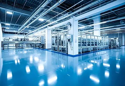
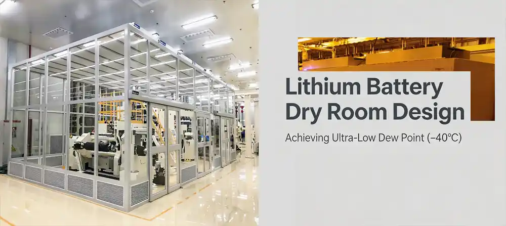
Lithium battery manufacturing requires precise moisture control to protect sensitive materials and ensure consistent product quality. A well-designed dry room must maintain an ultra-low dew point of around -40°C through effective desICcant dehumidification, airtight construction, controlled airflow, and continuous monitoring. This article introduces the key design principles for ACHieving reliable, energy-efficient humidity control in lithium battery production environments.
The Importance of Eliminating High Dew Point in Lithium Battery Production
In lithium-ion battery production, prevention of moisture is important as moisture at a level of just 50 ppm may cause a 3–8% drop in the first cycle capacity with a 12–20% rise in internal resistance. Those processes, which are more moisture sensitive, are the first step in determining the effective and dry room designs.
Processes of Lithium Battery Manufacturing that are Sensitive to Moisture
The stability of materials and the performance of electrochemical cells is of concern at the following processes:
- Storage of raw materials – Cathode and anode powders are hygroscopic.
- Mixing and Coating of Slurries – Moisture initiates hydrolysis and degradation of salt binders.
- Calendering and Slitting – Adsorbed moisture alters the mechanical properties of the electrode.
- Assembly of Cells – Moisture on separators or electrodes increases internal resistance.
- Filling of Electrolytes – LiPF₆ combines with H₂O to generate HF which deteriorates the internal structure.
- Formation and Aging – Excess moisture interrupts the formation of the SEI layer and the cycle of stability.
- Testing and packaging – The presence of moisture quickly decreases storage capacity of the device.
These zones do not require the same dew point. More moisture control is applied to high sensitivity and moisture critical processes and less in supporting processes, which also assists in reducing the energy load.
What Does -40°C Dew Point Mean?
Dew point is not the same as relative humidity. In cold and dry environments, relative humidity may not provide a true picture of the moisture content. Therefore, dew point is preferred for the dry room control and acceptance of batteries.
There is a difference between the design target and the operational capability. A dry room should be evaluated for continuous dew point performance and not just for the minimum value recorded during the commissioning.
There are two separate capabilities for “reaching -40°C” and “sustaining -40°C for months.” Acceptance should be based on the ability to recover after door openings, personnel entry, and production loading.
Dry Room Design Requirements for Battery Manufacturing
Room Zoning and Dew Point Classification
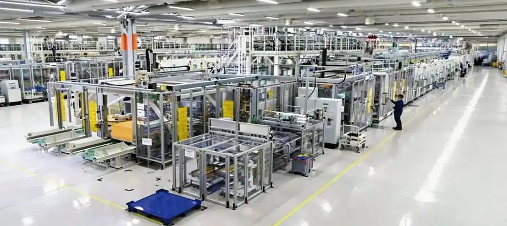
The table below summarizes typical zoning for a LiFePO₄ production line based on actual project specifications:
| Zone | Function | Typical Control Focus |
|---|---|---|
| Raw Material Area | Moisture absorption of materials | Prevention of materials degrading due to moisture absorption |
| Cell Assembly Area | Moisture preservation of electrodes and cells | Pick-up of moisture and control of access by personnel |
| Electrolyte Injection | Control reaction of electrolyte and moisture | to dew point and moisture control |
| Formation/Aging | Ensure consistency of product | Controls of moisture, temperature, and heat generated by the equipment |
| Buffer Zones | Control moisture-seeking personnel access | Air locks, pressure differentials, logic of door openings |
| Zone | Control Focus |
|---|---|
| Raw Material | Prevention of material degradation |
| Cell Assembly | Moisture pick‑up, personnel access |
| Electrolyte Injection | Dew point and moisture control |
| Formation/Aging | Moisture, temperature, equipment heat |
| Buffer Zones | Air locks, pressure, door logic |
Building Envelope and Airtightness
Ultra-low dew point systems will be ineffective if the building is not constructed to be tight. Continuous treatment of the perimeter of walls, ceilings, and floors is mandatory.
VbsQfJ5Gqo4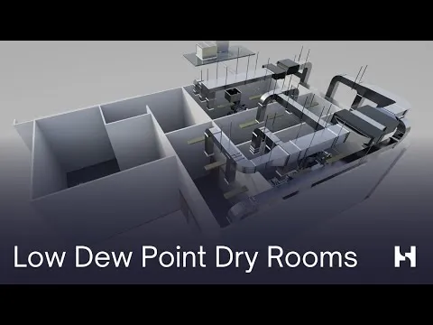
- Close all lines and fill all gaps in walls, ceilings, and floors.
- Ensure a continuous airtight seal between equipment and access panels.
- Control access by personnel; avoid overlapping and repetitive door access.
PRO-TIP: Envelope Micro-Leakage & Cold Bridge Detection
- Double-seal gasket on sandwich panels: Single gaskets provide 0.5–1.2 g/m³ infiltrations at a pressure of 25 Pa. Use EPDM and silicone dual-compression strips.
- Positive-pressure helium leak test: Inject 5% helium tracer into a plenum. It’s detected by a mass spectrometer, and leakage is < 0.01 m³/h.
- Smoke pen test: Visualize air flow in and around Doors, cable trays, and utility penetrations during a fan pressurization test; air paths will be visible.
- Cold bridge treatment at pipe penetrations: Use 100 mm phenolic foam sleeves with a two-layer vapor barrier. Condensation will occur if the surface temperature is at or below dew point.
- Thermal imaging audit: When the building envelope is under a steady state of operation, a scan of the envelope will show areas with compromised insulation when the thermal difference is greater than 3°C across a joint.
Airlock, Pressure and Personnel Flow
Improper gowning, air showers and airlock design allow moisture from clothing, shoes, and external air to enter a dry room. There is a continuous 3×10⁻² to 5×10⁻² Pa (0.03 to 0.05 Pa) energy loss.
- Separate personnel and material passages
- Provide anterooms or air locks
- Interlock doors based on closing status.
- Control pressure differential between the dry room and adjacent areas (recommended 0.03 to 0.05 Pa).
- Minimize simultaneous opening of two doors.
- Monitor high-traffic zones with priority sensors.
Pressure Cascade Logic & Airflow Organization
Corridor (P₀) → +5 Pa → Gown/Air Lock → +15 Pa → Buffer → +25 Pa → Dry Room (P₀+25)
Supply air: Ceiling-mounted HEPA diffusers (face velocity 0.15–0.25 m/s) provide a consistent downward flow. Return Air: Low-side wall grilles at 0.3–0.5 m height remove moisture-laden air. This vertical and uni-directional flow pattern minimizes air stratification and maintains a temperature gradient of less than or equal to 0.5°C.
The pressure cascade (25 Pa differential from corridor to dry room) guarantees that any air leakage from the dry room is forced out, preventing the ingress of humid air. Door interlocks and vestibule purge cycles help to protect the dry room from pressure collapse during personnel transit.
How Desiccant Dehumidification Achieves -40°C Dew Point
Working Principle of a Desiccant Dehumidifier
Cooling dehumidification alone cannot economically achieve the required dew point for battery drying. Desiccant dehumidification using solid adsorbents captures water vapor regardless of the saturation curve, making it suitable for absolute humidity levels below 1 g/kg.
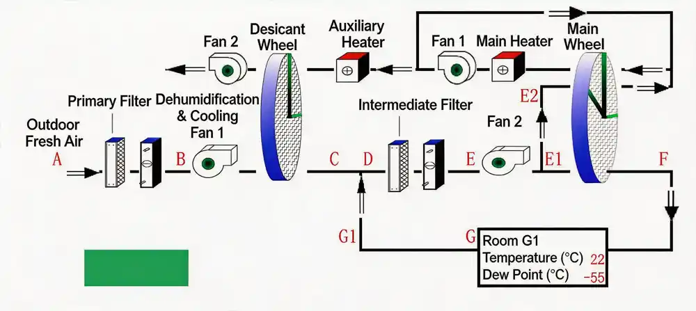
Process air path: Return air → Pre-cooling → Desiccant rotor → Post-cooling → Supply air → Dry room → Return air
Regeneration air path: Ambient air → Heating → Desiccant rotor → Moisture exhaust
Regeneration air path: Ambient air → Heating → Desiccant rotor → Moisture exhaust
The rotor captures moisture from the process air. Regeneration air, heated to desorb the captured moisture, carries it away. The system is self-regulating based on dew point, temperature, flow rate, and differential pressure.
Single-Stage vs. Two-Stage Rotor: Physical Limits & Energy Curves
For a single-stage desiccant rotor, there is an adsorption isotherm limit. The lower the moisture content in the inlet air, there is less driving force for moisture adsorption. When the absolute air humidity is lower than 2 g/kg (approximately -25°C dew point), the rotor loses its purpose. To reach 1 g/kg at the outlet, moisture, and 18–22 kW of energy is required to flow through every 1000 m³/h, at a rotor regeneration temperature of 140°C, (which is already quite high).
Two-stage rotors bypass that physical limit by adding an inter-stage cooling coil between the first and second rotors. The first rotor is used to remove the bulk of the moisture (down to 2.5–3.0 g/kg) and the air is then cooled to 12–15°C. At this temperature, moisture in the air starts to condense, and it adds to the relative humidity of the air. This moisture is now a driving force for the adsorption process. The second rotor can then outlet moisture below 0.024 g/kg (-50°C dew point) with a regeneration temperature of only 110–120°C.
Single-Stage
Min. outlet: 0.5–0.8 g/kg (-40°C borderline)
Regen. T: 130–160°C
Specific power: 18–22 kW/1000 m³/h
Adiabatic efficiency: 58–65%
Two-Stage
Min. outlet: 0.018–0.024 g/kg (-50°C stable)
Regen. T: 100–120°C
Specific power: 9–14 kW/1000 m³/h
Adiabatic efficiency: 78–85%
* Based on 35°C / 28°C WB outdoor condition, R410A DX pre-cool, electric regeneration.
Deiiang Product Data and Performance Evidence
Deiiang™ systems provide reliable low-dew-point cooling and dehumidification systems for the most demanding lithium battery manufacturing environments. The table below summarizes performance data from a 5 GWh lithium-ion battery factory:
| Parameter | Deiiang Actual Data | Notes |
|---|---|---|
| System Type | Two-stage rotary desiccant | Inter-stage cooling + independent regeneration |
| Plant Capacity | 5 GWh | Lithium-ion battery manufacturing |
| Process Zones | 5 zones ≤ -50°C dew point | Coating, drying, injection, and formation |
| Target Dew Point | ≤ -50°C (drying/injection rooms) | Exceeds -40°C |
| Absolute Humidity | < 0.024 g/kg | Drying room condition |
| Energy Recovery | Waste heat recovery | Significant reduction in regeneration energy |
| Regeneration Heat Source | Electric / steam (site-dependent) | Flexible utility interface |
| Control System | PLC + touchscreen + remote monitoring | BMS integration capable |
| Parameter | Deiiang Data |
|---|---|
| System | Two-stage rotary desiccant |
| Plant Capacity | 5 GWh |
| Target Dew Point | ≤ -50°C |
| Absolute Humidity | < 0.024 g/kg |
| Energy Recovery | Waste heat recovery |
There are three key data types: design value, commissioning value, and long-term operating value. Providing only the lowest dew point number is less credible than showing sustained performance in an actual production environment.
Dry Room Airflow & Energy Estimator
Quick estimate of required supply airflow and regeneration energy for a battery dry room
Supply airflow
— m³/h
— m³/h
Regeneration power
— kW
— kW
Total power (estimate)
— kW
— kW
Specific power
— kW/1000 m³/h
— kW/1000 m³/h
* Estimate based on two-stage desiccant at 35°C/28°C WB outdoors. Actual values depend on building envelope tightness, load, and control.
Localized Deiiang Case Study
Project Overview
For one localized battery manufacturing project, Deiiang™ ignored humidity problems and willfully designed a system based on the four aspects of moisture load, zone division, control of airflow, and control of operation, rather than just adding more units to the system.
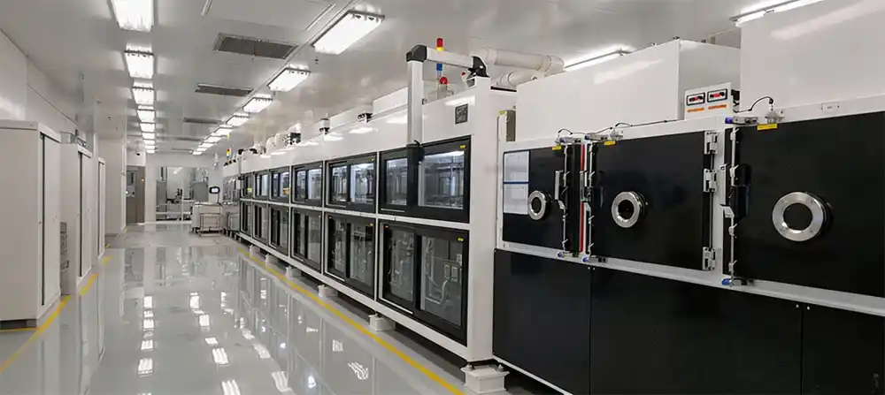
- Location: High-humidity area (seasonal outdoor dew point > 25°C).
- Battery type: LiFePO₄.
- Project capacity: 5 GWh.
- Whole dry room area: ≈ 12,000 m².
- Processes: Electrode coating, drying (pre-injection), electrolyte injection, formation/aging.
- Designed dew point: ≤ -50°C (for drying and injection rooms).
- System airflow: > 200,000 m³/h.
- Equipment: Several two-stage desiccant dehumidifiers with inter-stage cooling.
- Project duration: 18 months (from design to construction and commissioning).
- Deiiang responsibilities: Design of a complete HVAC system, supply of HVAC system, supervision of installation, and commissioning.
Local User Persona
General User: Battery Factory Project Manager.
Main Priorities:
- Equipment must be delivered on time to meet the tight project deadlines.
- High humidity means lots of moisture in the fresh air.
- Concerned with the increasing cost of energy and worried about the operating costs.
- Concerned with the existing, possibly limited, dehumidification during the production line expansion.
Daily installation scheduling provides clear cut interfaces for the local construction employees, and a time minimized commissioning process for the employees. Management expects to achieve production with consistent yields in the shortest time possible.
Supplying extended support of a project is important to the User, as is the ability to maintain the design dew point. Support must be extended to all aspects of the User’s needs, including maintenance and the controlled delivery of an energy efficient system. Design is important, but so too are stabilized systems. This includes a system that supports the needs of the User adequately during and after the project. Supply of support on the project site is a key concern and must be prioritized.
Project Challenges
- The high humidity and temperature had a fresh air moisture load that was 40% greater than the moisture loads defined by the existing project standards.
- Expansive production area — without meticulous duct designs, airflow distribution highly uneven.
- Space constraints on the premises — layout and access for equipment maintenance limited.
- Short-term dew point spikes up to -30°C occurred due to frequent door openings.
- Lower operational consumption was needed, but the dew point and energy costs were sensitive.
- Existing BMS integration meant there was a need for uninterrupted communications with the plant’s overall monitoring systems.
Deiiang's Solution
| Challenge | Deiiang Solution | Result |
|---|---|---|
| High moisture load | Two-stage desiccant with inter-stage cooling; waste heat recovery | Sustained -50°C dew point; regeneration energy reduced by 33% |
| Dew point fluctuation | Zoned control with dew-point-linked modulation | ±2°C stability during normal operation |
| Uneven airflow | Optimized supply/return layout with CFD validation | Uniform distribution; no dead zones |
| High energy cost | Optimized regeneration heat source + pre-cooling logic | 33% lower energy than single-rotor design |
| Maintenance access | Reserved service space + monitoring points | Routine maintenance completed without production stoppage |
| Challenge | Result |
|---|---|
| High moisture load | Sustained -50°C, regen energy -33% |
| Dew point fluctuation | ±2°C stability |
| Uneven airflow | Uniform distribution |
| High energy cost | 33% lower energy |
| Maintenance access | No production stoppage |
Project Photos
(Placeholder images — replace with actual Deiiang project photos where available.)
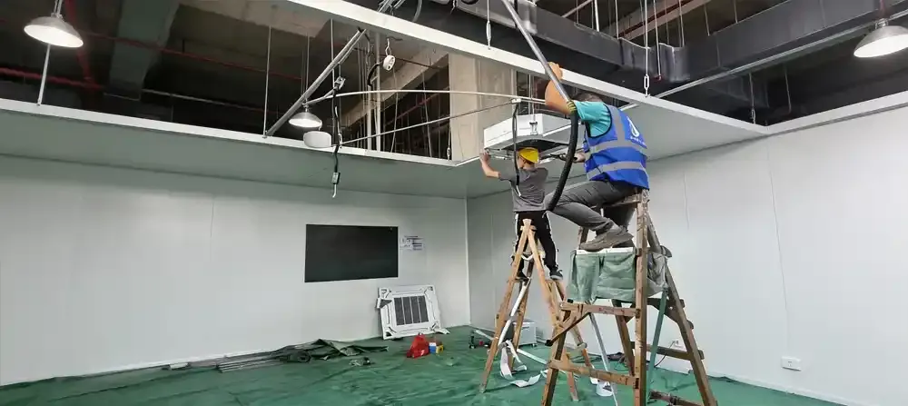
Desiccant dehumidifier installation
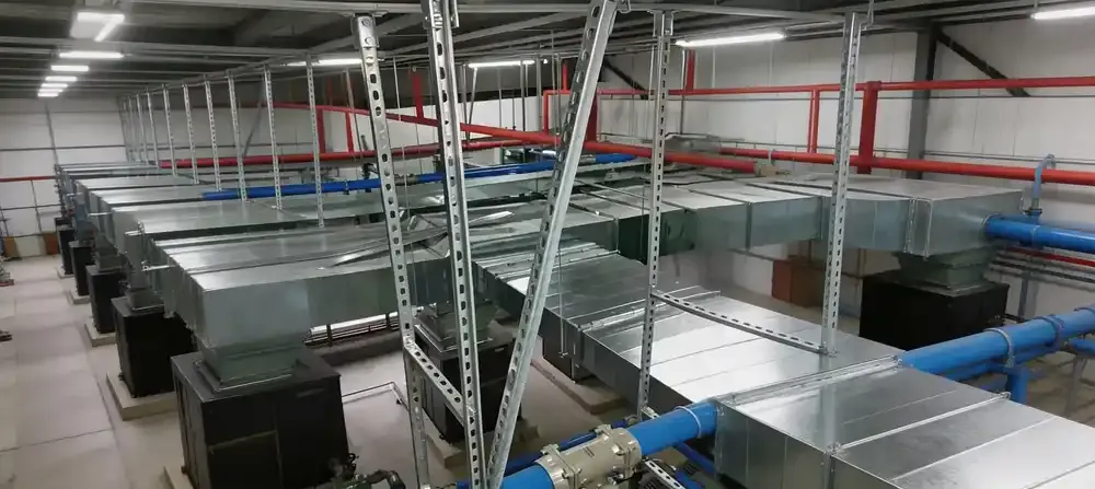
Ductwork and sealing detail
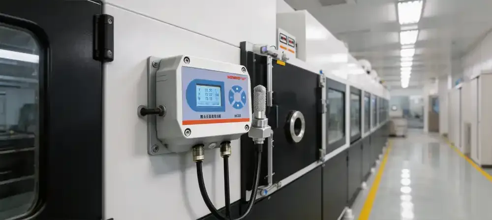
Dew point monitoring interface
Dry Room Project Workflow: From Design to Delivery
- Technical Requirement Confirmation — Identify type of battery and determine area requirements for compliance with dew point and temperature, the volume of fresh air, personnel count, door frequency, process moisture release, local outdoor design conditions, and available utilities.
- Moisture Load Calculation — Consider outdoor fresh air, envelope, infiltration, personnel, materials, process equipment, door openings, system leakage, and safety margin.
- Preliminary Design — Conduct equipment selection, system flow diagram, duct layout, supply/return scheme, control logic, energy interfaces, equipment arrangement, and service space.
- Detailed engineering & Manufacturing — Fabricate equipment, design and build control panels, conduct factory tests, compile documentation, package and ship, confirm interface on site.
- Installation & Commissioning — Conduct tests for airflow, temperature, dew point, differential pressure, check filters, conduct interlock test for doors, test alarms, conduct a continuous run test, and test for BMS communication.
- Acceptance & Handover — This includes operating logs, dew point trend charts, and calibration certificates. Other documents include airflow and pressure records, control program backups, O&M manuals, and spare part lists, along with training records and warranty terms.
Battery Dry Room Cost Considerations
CAPEX includes the dehumidification units, the cooling and regeneration units, the heat and moisture transport, the control systems, the filters, the building envelope and sealing, all the labor for the installation, transport, and the commissioning, as well as the building/civil works.
OPEX includes the cost of the heat used for regeneration (which can be electric or steam), the cost of chilled water or refrigeration, the cost of the fans, the cost of replacing filters (which can be quite frequent), the cost of replacing rotors and seals, the cost of calibration of sensors, the costs of maintaining spare parts, and the cost of labor.
Typical OPEX costs for a 5 GWh Dry Room
Regeneration Heating
48–56%
48–56%
Fans & Motors
18–24%
18–24%
Pre-cooling / Chiller
14–18%
14–18%
Controls & Aux.
8–12%
8–12%
ROI example: If we install a waste heat recovery system (which captures the regeneration exhaust that is at 55–65°C), the system costs approximately $120,000 and the cost of regeneration energy goes down by 28–32%. If we assume the cost of electricity is at $0.12/kWh and the company operates for 7,500 hours per year, the annual savings from this system will be between $82,000 and $94,000. Therefore, the payback period for this system will be 14 to 18 months.
For a typical 5 GWh facility, and to optimize the regeneration system of the dry room, the total annual OPEX of the dry room HVAC system will be between $1.2M to $1.7M. The optimization cost mentioned above can be between $280,000 and $380,000.
When considering the cost of a dry room, total cost of ownership should be evaluated, not just the initial equipment price.
What to Check Before Buying a Dry Room Dehumidification System
- Is a moisture load calculation provided?
- Is the dew point specified as either a design value or a long-term operational value?
- Is there access to actual test data from comparable projects?
- Has the equipment been tested in the local environment?
- Is there energy interface alignment (electric, steam, chilled water) to the system?
- Does the system allow for zoned control?
- Is integration with the BMS (Building Management System) or remote monitoring available?
- Is the required maintenance access area adequate?
- What are the maintenance procedures for rotor filters and sensors?
- What is the lead time for spare parts and delivery?
- Are acceptance criteria stated in the contract?
- What are the consequences of a project delay or if the specification is not met?
Energy-Saving Strategies for Control of Ultra-Low Dew Point
Reduce the Unnecessary Moisture Load
- Improve the building envelope airtightness.
- Reduce the number of personnel and material entries.
- Construct air locks with sequentially operated doors.
- Optimize the intake of outside air.
- Utilize localized exhaust for high humidity sources.
Optimize the System Functionality
- Employ control of variable air flow based on load.
- Establish independent dew point control for each zone.
- Source regenerator heat from low grade process waste heat.
- Right size the pre and post cooling.
- Incorporate a trend monitor to control unexpected moisture loads.
- Avoid operating all equipment at full load for prolonged durations.
Energy Optimization
Once available data is collected, monitor and record the following: energy per unit of air flow (kW/1000 m³/h), energy per unit area, regeneration energy fraction, fan energy, pre/post retrofit comparisons, and seasonal performance. For a two-stage Desiccant Dehumidification System, a typical specific power range is from 9.0 to 14.5 kW/1000 m³/h for deep drying applications.
Visual Content Plan
The diagrams below work with the technical description (placeholders - replace with relevant diagrams)
- Figure 1: Lithium battery dry room system diagram - process air and regeneration air paths.
- Figure 2: Moisture load source analysis - outdoor air, people, materials, door openings, processes.
- Figure 3: System configuration based on dew point level (-20°C, -40°C, -50°C) — dehumidification depth, airtight, energy, complexity of control, processes.
- Figure 4: Example of dew point moisture level from a Deiiang project, duration of tests, operational parameters, set point, measured value ranges and loading of devices, external conditions.
- Figure 5: Flowchart of delivery of project from confirming requirements to acceptance of performance.
Stable -40°C dew point during lithium battery manufacturing is not just an HVAC specification, it is a requirement to quality losses to materials, the yield of the process, and the long-term performance of the battery.
The dry room is most effective in removing moisture at the source and managing all pathways where moisture can enter.
Frequently Asked Questions
What dew point is necessary for lithium battery manufacturing?
This is dependent on the battery chemistry and processes. For processes that are more sensitive to moisture, a common design target is -40°C or lower. To establish the most accurate target, consult the customer’s specifications.
How is a dew point of -40°C achieved with a desiccant dehumidifier?
Dew point of -40°C can be achieved through the combined action of a spinning desiccant rotor that absorbs moisture, dry air regeneration, and pre and post cooling of the rotor. Advanced, two stage systems that utilize a cooling in between the stages yield even deeper drying.
Is a dew point of -40°C necessary for the entire battery factory?
Not really. Zoned design focusing on process sensitivity is more cost-effective. The lowest dew point is necessary in high risk zones only, like in the electrolyte filling and drying rooms.
What involves the energy consumption of a dry room?
The outdoor climate, the amount of fresh air, the tightness of the room’s thermal envelope, the frequency with which the door is opened, the number of people inside, the moisture load of the process, how well the equipment works, and how effective the control system is.
How long does the dry room design and construction process take?
It varies with the size of the equipment, how detail the design is, the condition of the site, how the transport of the equipment is done, and how the commissioning is done. The average construction period for a 5 GWh project with Deiiang™ is 18 months from the time of approving the design to the time of handing over the project fully.
What is a dry room acceptance test?
Testing of dew point, air temperature, the speed of air flow, control of pressure, alarms, interlocks, continuous operation, and control system.
This is an engineering article only. The sizing and performance of the system are the responsibilities of the qualified agencies based on site conditions.
References
- Design of a Low-Humidity Air Conditioning System for a 5 GWh Lithium Battery Plant
- iso 14644-1: cleanrooms and associated controlled environments
- ASHRAE Handbook — HVAC Applications