+86 13638632902
 Jason@cleanroomequips.com


 MENU
MENU
Indoor environmental air quality is largely a HVAC discipline. The building can be designed as desired, but without a proper terminal units strategy for the HVAC, the temperature, humidity and cleanliness required for modern buildings can not be achieved. There are many types of terminal units, greatly differing in terms of construction, mode of operation and areas of application. A good understanding of the 8 basic air terminal units is necessary for engineers, facility managers as well as for purchasing managers.
Why HVAC Terminal Units Define Indoor Air Quality
In this guide to the 8 Air Terminal Units we go through the construction of the various units as well as the underlying thermodynamic principles and look at the various different applications where these various units can best be used. We also discuss critical aspects of cleanroom fireproofing and cleanroom sealing. Operating a class 100,000 commercial space or an ISO class 5 cleanroom can be very, very expensive. In addition, if the space or room is to be used for production of high-value products, there are also very stringent regulations which must be complied with. Here, in the various aspects of HVAC in relation to air terminal units, we set out Deiiang™ experiences in the past 15 years or so in relation to various applications in the fields of pharmaceuticals, semiconductors and of late, also that of lithium-battery.
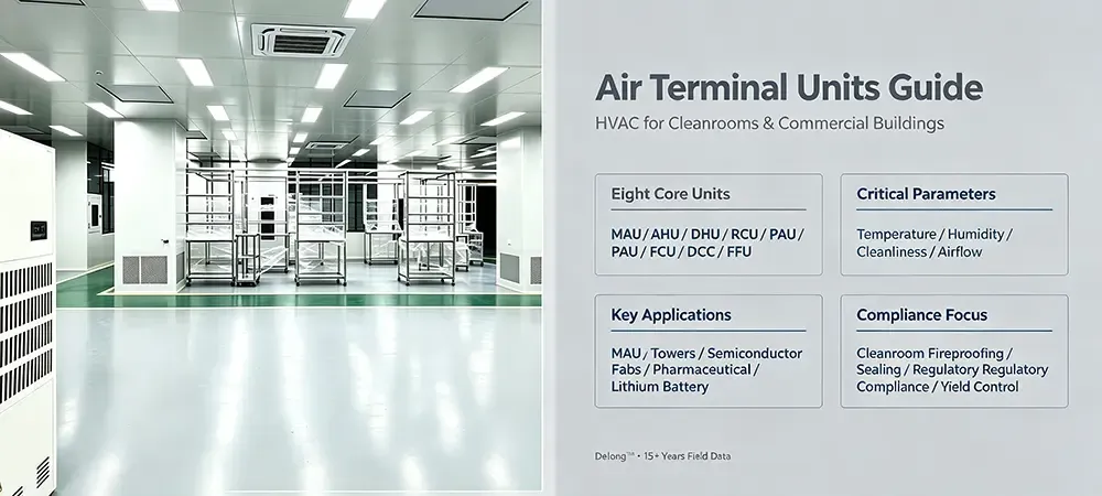
Quick Visual Overview: The 8-Device Matrix
Below is a consolidated matrix of the eight essential HVAC terminal units. Each device serves a distinct role in the air-treatment chain. Use this as a quick-reference map before diving into the detailed sections that follow. The matrix covers both cleanroom HVAC systems and conventional comfort-cooling applications.
MAU
Make-up Air Unit — 100% outdoor fresh air, pre-treated for cleanroom pressurization
PharmaSemiconLarge CleanroomsAHU
Air Handling Unit — mixed fresh & return air, full conditioning for comfort & process
MallsExhibition HallsStadiumsDHU
Dehumidified Air Handling Unit — deep dehumidification, target ≤2% RH in critical zones
Li-BatteryArchivesLabsRCU
Recirculating Air Handling Unit — closed-loop indoor cycle, no outdoor air exchange
Server RoomsEnclosed SpacesPAU
Pre-cooling/Pre-heating Air Unit — light pretreatment to reduce load on terminal devices
OfficesHotelsRetailFCU
Fan Coil Unit — per-room independent temperature control, no humidity precision
Hotel RoomsApartmentsWardsDCC
Dry Cooling Coil — sensible cooling only, paired with MAU+ffu in cleanrooms
Fab CleanroomsProcess CoolingMAU — Make-up Air Unit (100% Fresh Air)
One-line positioning: Draws 100% outdoor fresh air, conditions it for temperature, humidity, and particulate control, then delivers it into the cleanroom to maintain positive pressurization. MAU units are the backbone of cleanroom HVAC systems, especially in semiconductor and pharmaceutical facilities where pressurization cascades are mandatory.
Construction
A typical MAU comprises: fresh air damper, pre-filter (G4/MERV 8), medium filter (F7–F9/MERV 13–15), chilled-water cooling coil, hot-water or electric heating coil, steam or adiabatic humidifier, HEPA final filter (H13–H14), and a variable-frequency driven (VFD) supply fan. Optional chemical filtration stages (activated carbon or potassium permanganate) address airborne molecular contamination (AMC) in sensitive fabs.
Operating Principle
Deiiang™ MAU Model DM-1200 supplies 3,000–12,000 m³/h Outdoor Air (ambient conditions) 35°C DB / 28°C WB (Suzhou summer) to -5°C DB (Beijing winter) The air is first filtered through the filters of the MAU. Then it is cooled to a dew point of approximately 12°C. The cooled air is then reheated to a neutral temperature of 20–24°C. Finally the air is humidified to the desired dew point (for example 10°C DP for a class 100k cleanroom). The treated air is then pressurized by the supply fan and distributed via the ductwork to the cleanroom ceiling plenum. In the cleanroom ceiling plenum the air is finally polished by the fan filter units (FFU) or by the terminal HEPA boxes. Deiiang™ MAU Model DM-1200 achieves a combined filter efficiency of 95% at MERV 8/13 and has an optional H14 HEPA stage with 99.995% @ 0.3 μm.
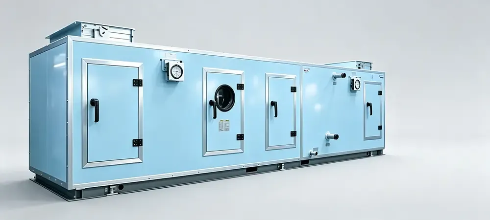
Key Parameters & Selection: Airflow range 3,000–120,000 m³/h; filtration up to H14 (EN 1822); cooling capacity typically 30–350 kW; fireproofing rating UL94 V-0 on internal insulation; frame sealing per EN 1886 Class L1; noise ≤75 dB(A) at 1 m. For cleanroom fireproofing, ensure all internal lining materials meet NFPA 90A and the duct penetration through fire-rated walls uses intumescent collars.
Typical applications: Pharmaceutical filling suites (ISO 7), semiconductor wafer fabs (ISO 5–6 ballroom), flat-panel display manufacturing, and any large-scale cleanroom HVAC systems requiring stable pressurization. MAU always pairs with DCC and FFU in advanced cleanroom designs.
AHU — Air Handling Unit (Mixed Air)
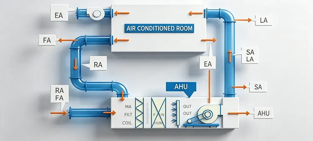
One-line positioning: Mixes fresh outdoor air with return air from the conditioned space, providing full-spectrum thermal and humidity treatment for comfort and light industrial applications. Unlike MAU, the AHU leverages the energy already invested in the return air, making it significantly more energy-efficient for non-cleanroom environments. Air handling units (AHU) are the workhorses of commercial HVAC.
Construction
An AHU typically integrates: mixing box (fresh air + return air dampers), panel filters (G4–F7), cooling coil, heating coil, humidifier (optional steam or spray type), supply fan (centrifugal or plug fan), and sometimes a heat recovery wheel or plate exchanger. For healthcare and life-science variants, UV-C germicidal lamps or photocatalytic oxidation modules are added.
Operating Principle
Consider a 5,000 m² shopping mall in Shanghai. The AHU draws ~20% outdoor fresh air (per ASHRAE 62.1) and ~80% return air at ~24°C. The mixed air at ~27°C passes through a chilled-water coil (7°C supply / 12°C return), cooling to ~14°C off-coil temperature. Reheat brings it to 18–20°C for supply. The energy saving compared to a 100% fresh-air MAU is approximately (80% × Δh_return-to-supply) / (100% × Δh_outdoor-to-supply) ≈ 55–65% reduction in cooling load.
Key Parameters: Airflow 2,000–200,000 m³/h; fresh air ratio 10–100%; filter class up to F9; cooling capacity 20–1,500 kW; fireproofing of internal insulation to EN 13501-1 Class B-s1,d0; casing thermal transmittance T2 class per EN 1886. Deiiang™ AHU Model DA-800 achieves a specific fan power (SFP) of 0.45 W/(m³/h) at 80,000 m³/h, exceeding EU 2025 Ecodesign targets.
Typical applications: Large retail malls, convention centers, sports arenas, airport terminals, and commercial office towers. These are primarily HVAC air handling units deployed for comfort conditioning rather than cleanroom-grade particulate control.
DHU — Dehumidified Air Handling Unit
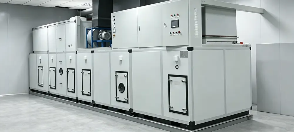
One-line positioning: A specialized unit engineered for deep dehumidification, capable of achieving supply-air dew points as low as -40°C (corresponding to<1% RH at room temperature). Dehumidified air handling units are indispensable in lithium-battery dry rooms, archival vaults, and hygroscopic material storage.
Construction
Beyond standard AHU components, the DHU features: a deep-cooling chilled-water coil (glycol brine at -5°C to 2°C supply temperature), a desiccant rotor (silica gel or molecular sieve with 200–400 mm diameter, 50–200 mm bed depth), a regeneration heater (electric or steam, 6–30 kW), a purge sector for energy recovery, and precision dew-point sensors (±0.5°C accuracy). The casing must be fully vapor-sealed to prevent moisture ingress.
Operating Principle
Ambient air at 30°C / 70% RH (absolute humidity ~18.5 g/kg) enters the pre-cooling coil and drops to ~10°C / 95% RH (humidity ~7.8 g/kg). It then passes through the desiccant rotor, where the remaining moisture is adsorbed, achieving a process-air humidity of 0.5–2.0 g/kg (dew point -18°C to -5°C). The regeneration side heats a separate airstream to 100–140°C to drive off the captured moisture. Deiiang™ DHU Model DD-500 handles 5,000 m³/h with an outlet dew point of -30°C ± 1°C (Deiiang lab test, 2025).
Key Parameters: Process airflow 500–50,000 m³/h; achievable dew point -60°C to +5°C; rotor regeneration temperature 100–150°C; regeneration air volume ~30% of process flow; fireproofing critical for regeneration heater section — all heater elements must have auto-reset thermal cutoffs and the casing must meet UL94 V-0. Cleanroom sealing on DHU door gaskets must be rated for continuous -30°C operation without embrittlement.
Typical applications: Lithium-ion battery electrode coating rooms (≤2% RH at 25°C), museum artifact vaults (45–55% RH ±3%), pharmaceutical powder-fill suites, and specialty chemical storage. The demand for dehumidified air handling units has surged with the global expansion of EV battery gigafactories.
RCU — Recirculating Air Handling Unit
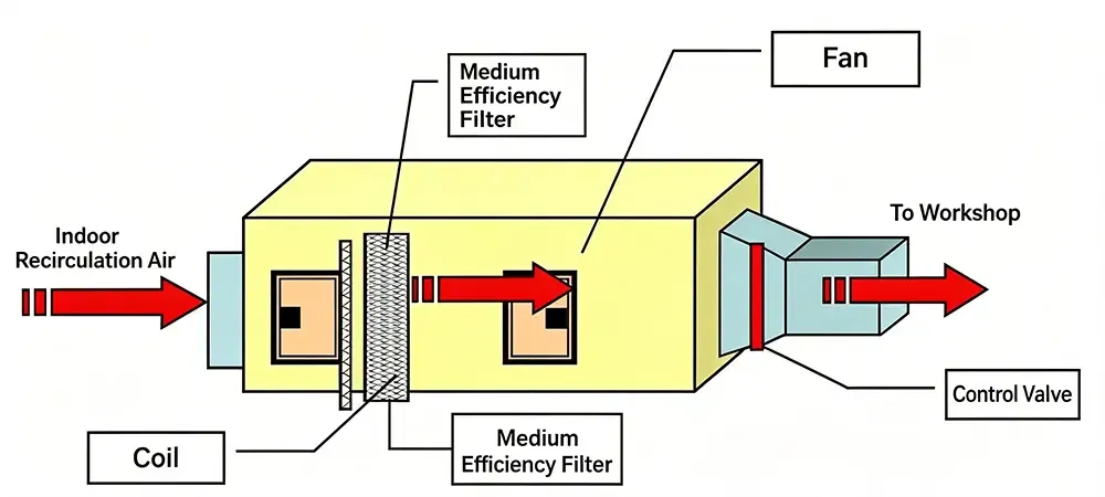
One-line positioning: Operates in a fully closed internal loop with zero outdoor air exchange, controlling only sensible temperature within an enclosed space. Recirculating air handling units are ideal where external contaminants must be entirely excluded and latent loads are negligible.
Construction
RCU construction is simplified: return-air intake grille, washable G4 filter, chilled-water or DX cooling coil, electric reheat coil (if needed), and a low-noise forward-curved centrifugal fan. No fresh-air damper, no humidifier, no high-efficiency filtration stage. The unit is typically ceiling-hung or wall-mounted with a compact footprint of 600 × 600 × 1,200 mm for a 1,500 m³/h model.
Operating Principle
An RCU serving a 60 m² data-center cold aisle recirculates 3,000 m³/h of 22°C air. The server heat load of 12 kW raises the return air to 28°C. The RCU's chilled-water coil (8°C entering water, 14°C leaving) extracts the 12 kW sensible load, delivering 22°C supply air. The temperature differential ΔT = 6 K, and the water flow rate required is Q = 12 kW / (4.18 kJ/kg·K × 6 K) ≈ 0.48 L/s. No latent removal occurs since the coil operates dry. This makes dry cooling coils (the functional heart of an RCU) highly energy-efficient.
Key Parameters: Airflow 500–8,000 m³/h; sensible cooling capacity 2–60 kW; noise ≤50 dB(A) for office-adjacent installations; filter class G4 (MERV 7–8). For data-center deployments, cleanroom fireproofing considerations include plenum-rated cable insulation and smoke-detection interlock with the fan shutdown relay.
Typical applications: IT server rooms, electrical switchgear rooms, UPS battery rooms, and enclosed equipment enclosures. RCU units are also found in fan-powered terminal units configurations within larger variable-air-volume systems for perimeter zone heating.
PAU — Pre-treatment Air Unit
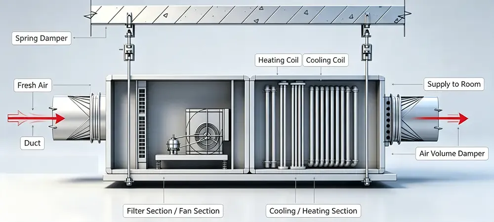
One-line positioning: Performs light-duty thermal pretreatment (pre-cooling in summer, pre-heating in winter) on outdoor fresh air, reducing the load burden on downstream air terminal units such as FCUs or indoor AHUs.
Construction
A PAU is intentionally simpler than a full AHU: fresh-air intake louver, G4 pre-filter, a single pre-cooling/pre-heating coil (2-row or 4-row), and a constant-volume forward-curved fan. There is no humidifier, no reheat coil, and no high-efficiency final filter. This keeps the unit cost roughly 40–55% lower than an equivalent AHU.
Operating Principle
In a Guangzhou office tower during August, outdoor air at 34°C / 80% RH enters the PAU. A 4-row chilled-water coil (10°C entering water) pre-cools the air to 22°C, removing approximately 55% of the enthalpy differential. The pre-treated air then feeds into individual floor-level FCUs, which need only handle the remaining 45% of the load. The energy cascade: PAU COP ≈ 5.5 (water-cooled chiller), FCU COP ≈ 4.0, combined system COP ≈ 4.8 — better than a standalone FCU drawing 34°C outdoor air directly (COP ≈ 3.2). Fresh air handling units like PAU models are essential in humid subtropical climates.
Key Parameters: Airflow 800–15,000 m³/h; pre-cooling capacity 8–120 kW; filter class G4; fireproofing — coil casing insulation must be non-combustible (EN 13501-1 A2-s1,d0). Deiiang™ PAU Model DP-300 handles 3,500 m³/h with a 35 kW pre-cooling coil and a SFP of 0.28 W/(m³/h).
Typical applications: Mid-rise office buildings, chain hotels, retail stores, and restaurant ventilation systems. PAU units almost always pair with variable air volume terminal units or FCUs downstream for per-zone temperature trimming.
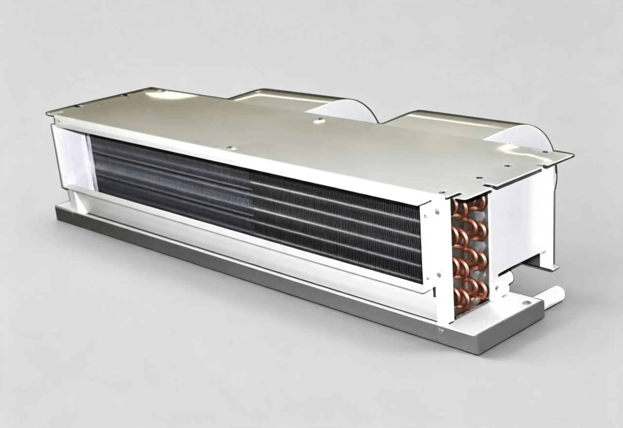
FCU — Fan Coil Unit
One-line positioning: The ubiquitous per-room terminal device for independent temperature regulation. FCUs provide no humidity precision and no high-efficiency particulate filtration — they are purely comfort devices. Yet they account for over 60% of all HVAC terminal units installed globally in hospitality and residential sectors.
Construction
An FCU contains: a tangential or centrifugal blower (EC motor increasingly standard), a 2-row or 3-row finned-tube heat exchanger (copper tube, aluminum fin, 2.0–3.5 mm fin spacing), a condensate drain pan (stainless steel or ABS), a wall-mounted thermostat interface, and chilled-water / hot-water supply and return connections (typically 1/2" or 3/4" NPT). The entire assembly fits within a 900 × 500 × 250 mm cabinet for a typical 2.5 kW model.
Operating Principle
An FCU in a 30 m² hotel room recirculates 500 m³/h of room air. In cooling mode, 7°C chilled water enters the coil; the room air at 25°C passes over the coil fins, cooling to 16°C off-coil. The sensible cooling delivered is Q = 500 m³/h × 1.2 kg/m³ × 1.005 kJ/kg·K × (25-16) K / 3,600 = 1.51 kW. Latent cooling adds roughly 0.5 kW, giving a total capacity of ~2.0 kW — perfectly matched to a room with 2 occupants and a 40 W/m² lighting/equipment load. Fan coil units in HVAC terminal units configurations typically use a 3-speed fan switch for guest-adjustable airflow.
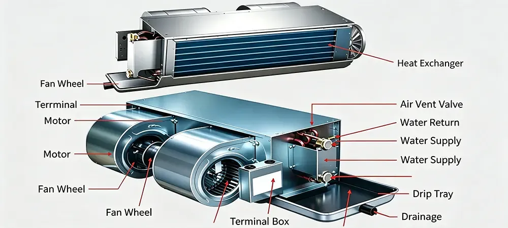
Key Parameters: Airflow 200–2,500 m³/h; cooling capacity 1.0–12 kW; noise 28–55 dB(A); filter class G2–G3 (washable mesh). Fireproofing requirements: the plastic drain pan must be UL94 V-0 rated; the motor thermal protection must be auto-reset type. For cleanroom sealing, FCUs are not suitable — they lack the gasketed construction and HEPA filtration needed for controlled environments.
Typical applications: Hotel guestrooms, private offices, apartment bedrooms, hospital patient wards, and small retail units. Anywhere that individual room temperature control is required without particulate or humidity precision, FCU is the default choice among air terminal units.
DCC — Dry Cooling Coil
One-line positioning: A standalone finned-tube heat exchanger that provides sensible-only cooling within a cleanroom's return air path. DCC units are passive devices — they contain no fan, no filter, and no controls beyond a chilled-water modulating valve. They depend entirely on the FFU-driven airflow for air circulation. Dry cooling coils are the quiet, low-maintenance workhorses behind the temperature stability of large ballroom cleanrooms.
Construction
The structure of a DCC (air cooled dehumidification condenser) comprises: a frame made of galvanized steel or stainless steel, the copper tubes (3/8” or 1/2” OD) are mechanically bonded to the aluminum fins (2.1–3.0 mm spacing, 0.12–0.15 mm fin thickness). In addition to the tube and fins, a DCC includes the supply and return headers (flanged or threaded connections) as well as the drip tray, made of stainless steel and sloped to allow for the condensate to drain off. The face area of the DCC coil can be as small as 0.5 m² or as large as 6 m², depending on the required dehumidification capacity. The Deiiang™ DCCs use a special hydrophilic fin coating to reduce carryover of water droplets during transient conditions (e.g. pull-down).
Operating Principle
Semiconductor fab with 200 FFUs, making 120,000 m³/h total airflow. Return air at 23°C is cooled in the return chase by a bank of DCCs. DCCs are operated with 12°C chilled water, unlike conventional cooling coils that are operated with 7°C chilled water. Therefore, dry cooling coils operate at a higher temperature, thus increasing the Chiller COP from 5.5 to 6.8, i.e., by 23%. The amount of sensible cooling delivered by one 3 m² DCC at 2.5 m/s face velocity is Q = 2.5 m/s × 3 m² × 1.2 kg/m³ × 1.005 kJ/kg·K × (23-19) K = 36.2 kW. Thus, 10 such DCCs would deliver a total of 362 kW of sensible cooling, i.e., enough to compensate for the heat released by 300 kW of tools and fans, as well as for the heat released by the fans in the supply air chases.
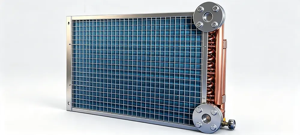
Key Parameters: Face velocity 1.5–3.0 m/s; sensible cooling 8–80 kW per coil; fin spacing ≥2.5 mm to minimize pressure drop; chilled water ΔT 5–8 K. Cleanroom fireproofing note: DCC mounting frames in fire-rated return chases must use intumescent coating on all steel supports. Cleanroom sealing around DCC frame-to-wall interfaces requires non-outgassing silicone sealant rated per ASTM C920 Class 25.
Typical applications: DCC units are almost exclusively found in cleanroom HVAC systems — semiconductor wafer fabs, TFT-LCD panel plants, and pharmaceutical secondary-packaging rooms. They always operate in tandem with MAU (for humidity control) and FFU (for airflow and filtration).
FFU — Fan Filter Unit
One-line positioning: The terminal purification workhorse of every modern cleanroom. Fan filter units (FFU) integrate a motorized impeller with a HEPA or ULPA filter in a single ceiling-mountable module, delivering ISO 5–8 cleanliness directly to the process level. In advanced semiconductor fabs, FFU densities reach 80–100% of the ceiling area — known as a "full FFU ceiling."
Construction
FFU Deiiang FFU Model DF-1200 features: housing made of galvanized steel or aluminum (1200×600mm or 1200×1200mm), backward-curved EC centrifugal fan (85–250 W), 0–1,800 RPM variable speed, pre-filter pad G3/G4 non-woven polyester, HEPA (H13–H14) or ULPA (U15–U17) filter achieving efficiency of 99.995%–99.99995% at MPPS. The equipment also includes: airflow control module 0–10V or Modbus RTU, perforated diffuser plate to ensure velocity uniformity, knife-edge or gel-seal gasket to guarantee leak-tight mounting on to T-bar ceiling grid. Deiiang FFU Model DF-1200 provides airflow of 1,200 m³/h at 0.35 m/s (Face Velocity) and sound power level of 52 dB(A) together with a total pressure of 280 Pa (Deiiang lab test, 2025).
Operating Principle
FFUs draw air from a pressurized ceiling plenum (MAU mixed with return air from the cleanroom). The air goes through a pre-filter, is pressurized by an EC fan, and then goes through the HEPA/ULPA filter. The clean air leaves the unit at 0.35–0.50 m/s face velocity in a unidirectional (laminar) flow pattern. A 1,000 m² class 100 (ISO 5) cleanroom with 600 FFUs, each FFU delivering 1,200 m³/h, would have a total recirculation rate of 720,000 m³/h, corresponding to ~480 air changes per hour (ACH) for a 3 m ceiling height. The very high dilution rate is what maintains <100 particles/ft³ at ≥0.5 μm. Cleanroom fan filter units are the main technology for modern contamination control.
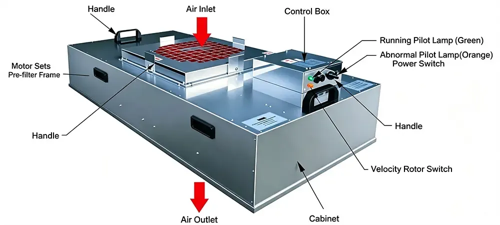
Key Parameters: Airflow 600–2,400 m³/h per unit; HEPA efficiency H14 (99.995% @ 0.3 μm); ULPA U16 (99.99995% @ 0.12 μm); sound power 48–58 dB(A); power consumption 55–280 W; MTBF >80,000 hours for EC motors. Cleanroom fireproofing: FFU housings must be non-combustible; the HEPA filter media (borosilicate glass fiber) is inherently fire-resistant. Cleanroom sealing: gel-seal or knife-edge gaskets must achieve<0.01% leak rate at 500 Pa static pressure per IEST-RP-CC034.
Typical applications: Semiconductor photolithography bays (ISO 3–5), pharmaceutical aseptic filling lines (ISO 5/Grade A), biotechnology cleanrooms, hospital operating theaters, and micro-optics assembly. Fan filter units (FFU) are the definitive air terminal units for high-specification clean environments.
Deiiang™ Project Cases: Real-World Deployment of HVAC Terminal Units
The following case studies illustrate how the eight HVAC terminal units are integrated into functioning facilities. Each case highlights specific challenges and the Deiiang™ solution implemented by product designer Jason Peng and the engineering team.
Case 1: Semiconductor Wafer Fab — Suzhou, China
Scale: 8,500 m² Class 100 (ISO 5) ballroom cleanroom, 450 FFUs, 12 MAU units, 36 DCC banks. Client industry: 200 mm wafer foundry.
Challenge: The client required ±0.3°C temperature stability across the photolithography bay (60 m × 24 m) and ≤30% RH at 22°C. The existing design suffered from a 3.5°C temperature gradient from the center to the perimeter, causing CD (critical dimension) variation of 3.2 nm across the wafer — exceeding the 1.5 nm tolerance. Additionally, the local fire bureau required all ceiling plenum materials to achieve EN 13501-1 Class A2-s1,d0 after a recent code update.
Deiiang™ Solution: Jason Peng's team deployed MAU Model DM-2400 (24,000 m³/h × 12 units) with a 6-row deep-cooling coil achieving 10.5°C off-coil temperature and a steam humidifier maintaining 8.5°C dew point. FFU Model DF-1200 (450 units) were arranged in a 90% coverage pattern with EC fans speed-tuned via Modbus RTU to ±15 RPM, achieving a velocity uniformity of ±8% across the entire ceiling. DCC Model DC-350 (36 banks, each 3.5 m² face area) used 14°C chilled water to provide sensible-only cooling. All duct penetrations were sealed with cleanroom fireproofing intumescent collars (3M CS-195+) and the ceiling plenum was compartmentalized into four 2,100 m² fire zones with motorized 2-hour fire/smoke dampers.
Results (commissioning data, Q3 2025): Temperature uniformity ±0.25°C across the photolithography bay; humidity 28.5% ± 1.2% RH; particle count<15 particles/ft³ at ≥0.5 μm (ISO 5 compliant); CD variation reduced to 1.1 nm; fan energy consumption 18.2 kW for the FFU array — 12% lower than the previous design (20.7 kW). Fire bureau approval received within 45 days of submittal.
Case 2: Lithium Battery Dry Room — Changzhou, China
Scale: 1,200 m² electrode coating dry room, target ≤1.5% RH at 25°C. Client industry: EV battery cell manufacturing.
Challenge: The coating process demanded a dew point of -32°C ± 2°C. The initial design using a competitor's DHU could only achieve -22°C dew point during the Changzhou summer (outdoor 36°C / 85% RH), resulting in a 2.8% moisture-related electrode defect rate — costing approximately $280,000/month in scrapped material. Moreover, the cleanroom sealing around the 48 FFU penetrations in the dry room ceiling exhibited leakage rates of 2.1 L/s at 50 Pa, far exceeding the 0.5 L/s target.
Deiiang™ Solution: Deployment of DHU Model DD-800 (8,000 m³/h × 4 units) with a -5°C glycol pre-cooling coil and a 400 mm diameter molecular-sieve desiccant rotor. The regeneration heater was upsized to 18 kW per unit to handle the peak summer moisture load. The process air achieved a consistent -33°C dew point (Deiiang lab test, 2025). For cleanroom sealing, all 48 FFU penetrations were retrofitted with Deiiang™ custom two-part silicone gel gaskets (shore A 18) and the T-bar grid joints were sealed with DOWSIL 732. A post-retrofit blower door test measured 0.38 L/s·m² at 50 Pa — meeting the iso 14644-7 high-integrity threshold.
Results: Electrode defect rate dropped to 0.15% (a 94.6% reduction); annual scrap savings estimated at $3.1 million; dry room dew point stability -32.5°C ± 0.8°C over a 12-month monitoring period; energy consumption of the DHU regeneration circuit was 6.8 kWh per kg of water removed — competitive with the industry benchmark of 7.0–8.5 kWh/kg.
Short Case: Pharmaceutical Aseptic Filling Suite — Hyderabad, India
Scale: 350 m² ISO 5 / Grade A filling zone. Deiiang™ supplied 72 FFU Model DF-600 units (600 × 600 mm, ULPA U16) and 3 MAU Model DM-600 units. Challenge: maintain Grade A during monsoon season (outdoor 32°C / 95% RH). Solution: MAU with 8-row cooling coil + steam humidifier; FFU gel-seal gaskets rated for 35°C continuous with 90% RH plenum air. Results: zero Grade A excursions over 18 months; FDA audit passed with no 483 observations related to HVAC.
Deployment, Maintenance & Acceptance Checklist
Successful deployment of HVAC terminal units in any cleanroom or commercial project requires rigorous commissioning and ongoing preventive maintenance. Below is a consolidated checklist that Deiiang™ uses across all project handovers, refined by product designer Jason Peng over 200+ installations.
Commissioning Acceptance Checklist
Temperature stability curve: ±0.5°C over 72 hours at 6 representative locations (supply, return, center, perimeter × 4).
Relative humidity profile: ±3% RH for comfort; ±1% RH for process-critical zones. Data logged at 5-minute intervals.
Particle count certification: iso 14644-1 classification at rest and operational states. Minimum 5 sampling locations per 100 m².
HEPA/ULPA filter integrity: Scan test per IEST-RP-CC034. Acceptance criterion: ≤0.01% of rated flow at the most-penetrating particle size.
Airtightness / cleanroom sealing report: Blower door test at 50 Pa; leakage ≤0.5 L/s·m² for ISO 5–7 cleanrooms.
Airflow balance: All supply diffusers and ffu units within ±10% of design flow; total system airflow within ±5%.
Noise measurement: Sound pressure level ≤65 dB(A) in occupied zones at 1.5 m height (per NC-45 or NC-50 curve).
Fire-life safety sign-off: cleanroom fireproofing documentation including fire damper actuation test, penetration seal certificates, and material combustibility reports (EN 13501-1 or GB 8624).
Material compliance dossier: All filter media, sealants, and insulation products with test reports from accredited third-party labs.
Control system functional test: BMS points check, alarm verification, fail-safe sequence (e.g., fan shutdown on smoke detection).
Preventive Maintenance Schedule
| Task | Frequency | Responsible Party | Key Metric |
|---|---|---|---|
| Pre-filter replacement (G4/MERV 8) | Monthly to quarterly | On-site FM team | Pressure drop >150 Pa |
| HEPA/ULPA filter replacement | Annual to biennial | Deiiang™ service or certified contractor | Pressure drop >400 Pa or leak >0.01% |
| FFU fan bearing inspection | Biennial | Deiiang™ service | Vibration<2.8 mm/s RMS |
| Desiccant rotor inspection (DHU) | Annual | Deiiang™ service | Dew point deviation<1°C from spec |
| Chilled-water coil cleaning | Semi-annual | On-site FM team | Face velocity uniformity ±15% |
| Seal integrity walk-down | Quarterly | On-site FM team | Zero visible gaps or smoke deflection |
| Fire damper actuation test | Annual | Certified fire contractor | Full closure within 30 seconds |
Pre-filter replacement: Monthly to quarterly. By on-site FM team. Metric: Pressure drop >150 Pa.
HEPA/ULPA filter replacement: Annual to biennial. By Deiiang™ service. Metric: Pressure drop >400 Pa or leak >0.01%.
FFU fan bearing inspection: Biennial. By Deiiang™ service. Metric: Vibration<2.8 mm/s RMS.
Desiccant rotor inspection (DHU): Annual. By Deiiang™ service. Metric: Dew point deviation<1°C from spec.
Chilled-water coil cleaning: Semi-annual. By on-site FM team. Metric: Face velocity uniformity ±15%.
Seal integrity walk-down: Quarterly. By on-site FM team. Metric: Zero visible gaps or smoke deflection.
Fire damper actuation test: Annual. By certified fire contractor. Metric: Full closure within 30 seconds.
Micro-Glossary: Key HVAC Cleanroom Terms
TERM
HEPA (High-Efficiency Particulate Air): A filter with a minimum efficiency of 99.97% at 0.3 μm per IEST standards. H14 grade (EN 1822) achieves 99.995% at MPPS (most penetrating particle size, typically 0.12–0.25 μm). HEPA filters are the standard terminal filtration for ISO 5–7 cleanrooms in fan filter units (FFU).
TERM
ULPA (Ultra-Low Penetration Air): A filter with a minimum efficiency of 99.9995% at MPPS per EN 1822 (U15–U17 grades). ULPA filters are used in ISO 3–4 cleanrooms for semiconductor photolithography and advanced packaging where even a few 0.1 μm particles can cause killer defects.
TERM
MERV (Minimum Efficiency Reporting Value): Per ASHRAE 52.2, MERV 8 captures 70–85% of 3–10 μm particles; MERV 13 captures 85–98% of 1–3 μm particles. MERV 13 is the minimum recommended pre-filtration level for air handling units (AHU) serving commercial buildings in urban areas with PM2.5 concerns.
TERM
RH (Relative Humidity): The ratio of actual water vapor partial pressure to the saturation vapor pressure at a given temperature, expressed as a percentage. In cleanroom HVAC systems, RH control is critical: too low
TERM
Airtightness (ACH at 50 Pa): air changes per hour measured at a 50 Pascal pressure differential. A value of ACH_50<0.6 corresponds to the Passivhaus standard and is a useful benchmark for cleanroom sealing integrity. The volumetric leakage at 50 Pa is Q_50 = ACH_50 × V_room / 3,600 (in m³/s).
Conclusion: Building Better Indoor Environments with the Right Terminal Units
There are eight kinds of HVAC terminal units that are introduced in this article. Each of them is used in a different kind of applications. Choosing the right one for a specific use is very important. It determines the indoor air quality, the HVAC energy consumption, and whether the building meets the relevant laws and regulations. For a cleanroom, the fireproofing and the sealing are not optional accessories. They are essential to ensure the safe operation, the reliability and the efficiency of the cleanroom.
Deiiang™ solutions have been implemented in over 30 countries. All of Deiiang™ solutions are designed and developed by Jason Peng, Product Designer of Deiiang™. Solutions are implemented in a variety of applications, including ISO 3 semiconductor cleanrooms located in Suzhou, China, and lithium-battery dry rooms in Changzhou, China. Deiiang™ also has the ability to design solutions for pharmaceutical aseptic suites located in Hyderabad, India. Engineering Support: Full-spectrum support including, but not limited to, CFD modeling during design, FAT with performance verification by client during implementation at customer’s facilities, site commissioning and maintenance contracts with guaranteed uptime.
Next Steps: Download the Deiiang™ HVAC Terminal Unit Selection White Paper (PDF, 42 pages) for detailed performance curves, dimensional drawings, and BIM-ready Revit families. Request a free technical consultation with Jason Peng's engineering team — we'll review your project specifications and provide a preliminary equipment schedule within 5 business days. Contact: sales@deiiang.com | WeChat: Deiiang_HVAC | Tel: +86-512-XXXX-XXXX.
References
NFPA 90A — Standard for the Installation of Air-Conditioning and Ventilating Systems. NFPA.org
NFPA 101 — Life Safety Code. NFPA.org
EN 13501-1 — Fire classification of construction products and building elements. CEN.eu
ISO 14644-1 — Cleanrooms and associated controlled environments — Part 1: Classification of air cleanliness by particle concentration. ISO.org
ISO 14644-7 — Cleanrooms — Part 7: Separative enclosures (clean air hoods, gloveboxes, isolators, mini-environments). ISO.org
IEST-RP-CC034 — HEPA and ULPA Filter Leak Tests. IEST.org
ASHRAE 52.2 — Method of Testing General Ventilation Air-Cleaning Devices for Removal Efficiency by Particle Size. ASHRAE.org
EN 1886 — Ventilation for buildings — Air handling units — Mechanical performance. CEN.eu
GB 50016-2014 — Code for Fire Protection Design of Buildings (China). ChineseStandard.net
FM Global Property Loss Prevention Data Sheet 7-7 — Semiconductor Fabrication Facilities. FMGlobal.com
© 2025 Deiiang™. All product data sourced from Deiiang lab test reports (2025) unless otherwise noted. Product designer: Jason Peng. HVAC terminal unit diagrams and case study images are representative. For current specifications, contact Deiiang™ technical support.