+86 13638632902
 Jason@cleanroomequips.com


 MENU
MENU
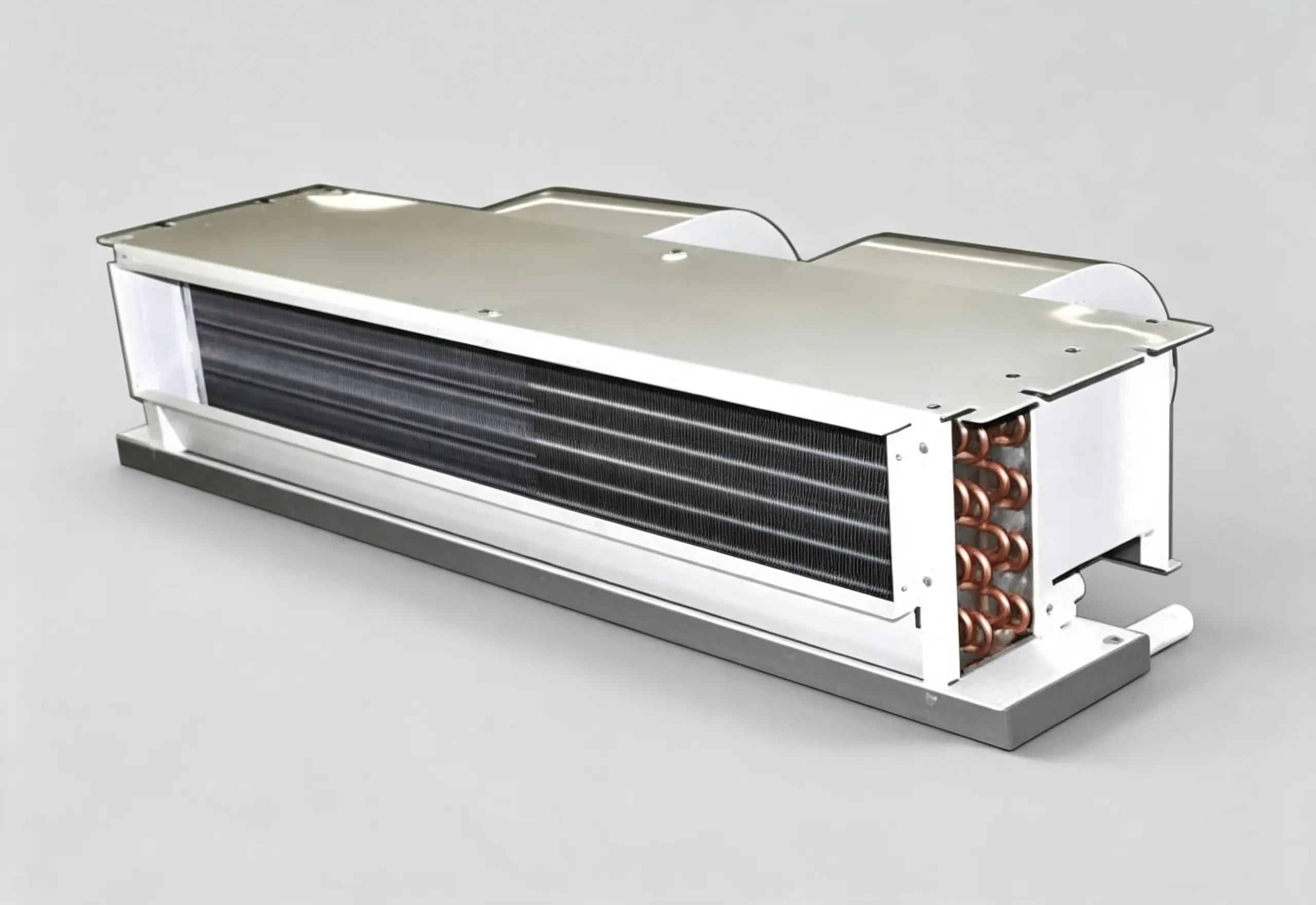
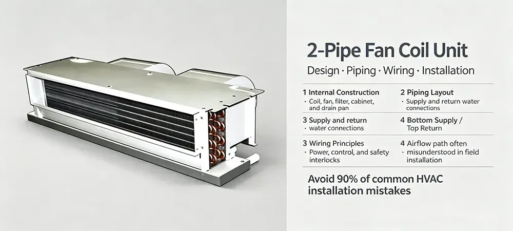
While rare to find an HVAC technICian who hasn't worked with a 2 pipe FCU (Two Pipe Fan Coil Unit) in some form, most people do not realize how much intricate design goes into what appears to be a simple box with 2 pipes and a fan. These little terminal units (TTU) are found in just about every Hotel, Office Building, clean room Support Area, as well as Residential High-Rise buildings across the United States and many countries worldwide. In many cases simple does not equal easy.
In this article, we will describe the components of a 2 pipe fan coil unit, review the piping and wiring options for these terminal units, and then review the often misunderstood bottom-supply, top-return configuration of these units. Once you have read this article, you will be able to effectively specify 2 pipe fan coil units for new construction as well as diagnose and repair problems with existing systems. Product design is by Deiiang™, engineers, and lead product designer Jason Peng.
Structural Principles of Two-Pipe Fan Coil Units
Before we look at piping and wiring for two pipe fan coil units, we first need to get to grips with the basic Structural Principles of Two-Pipe Fan Coil Units. A simple 2 pipe fan coil unit consists of a heat exchanger coil, a blower, a condensate management system and an electrical enclosure. However, eACH of these components has a number of different factors that affect the overall thermal performance, acoustic performance and maintainability of the unit. In general, a two pipe fan coil unit is designed to last for 15-20 years or more.
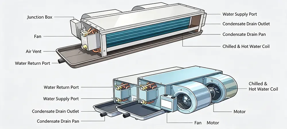
The two pipe fan coil unit is named from the two water connections required for a single coil, i.e. one supply connection and one return connection. In cooling mode the chilled water is approximately 7°C (44.6°F) entering the coil, and in heating mode the hot water is approximately 45–60°C (113–140°F) entering the coil, the same coil being used for both modes of operation. This changeover mode of operation is typically used for 2 pipe FCUs, as opposed to four pipe FCUs which are designed for year-round simultaneous operation and use separate cooling and heating coils.
Core components at a glance:
Cooling/Heating Coil: Copper tubes mechanically bonded to aluminum fins — the primary heat exchange surface. Typical fin spacing ranges from 8 to 14 fins per inch (FPI), balancing heat transfer against air-side pressure drop.
Blower & Motor Assembly: A double-suction centrifugal fan driven by a low-noise PSC or ECM motor, selectable across High / Medium / Low speed taps. ECM motors can reduce fan energy consumption by 30–50% compared to PSC equivalents.
Condensate Drain Pan & Outlet: Positioned beneath the coil with a built-in slope (minimum 1:100 gradient) to direct condensate toward the drain connection — typically a 3/4-inch PVC slip joint.
Manual Air Vent & Junction Box: A top-mounted bleed valve for purging trapped air, and a side-mounted sealed electrical enclosure housing all field wiring terminations.
Design Insight: On a 2 pipe FCU installation where the coil is rated for 400 CFM nominal airflow, a mere 5% reduction in airflow due to dirty filters or obstructed return grilles can drop sensible cooling capacity by approximately 8–12%. Deiiang™ engineering data from Jason Peng's thermal lab tests confirm that maintaining clean filters and coil surfaces preserves up to 95% of rated capacity over a 3-year operational period.
Two-Pipe Fan Coil Unit Piping Layout
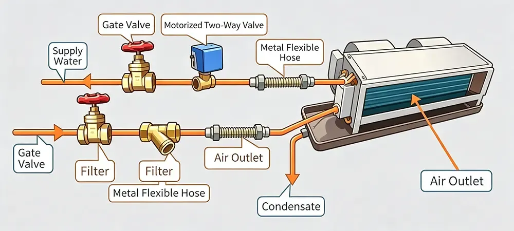
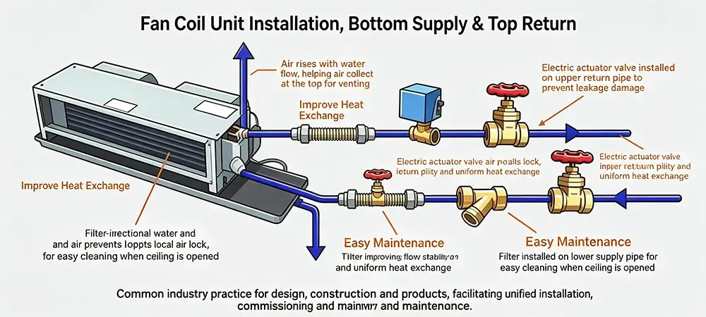
Piping a 2 pipe fan coil unit correctly is as critical as selecting the unit itself. The standard arrangement follows a logical sequence designed for maintainability and hydraulic stability. On the supply (bottom) side, the components are ordered: Gate Valve → Y-Strainer → Flexible Metal Hose → Coil Inlet. On the return (top) side: Coil Outlet → Flexible Metal Hose → Motorized 2-Way Valve → Gate Valve. This seemingly simple sequence is the result of decades of field experience with HVAC installation mistakes that taught engineers what not to do.
| Pipe Side | Component Sequence (In → Out) | Function | Service Note |
|---|---|---|---|
| Supply (Bottom) | Gate Valve → Y-Strainer → Flex Hose | Isolation + Filtration + Vibration Isolation | Clean Y-strainer mesh (typically 20–40 mesh) every 6 months |
| Return (Top) | Flex Hose → Motorized Valve → Gate Valve | Vibration Isolation + Flow Control + Isolation | Valve actuator rated for 100,000+ cycles in normal operation |
| Condensate | Drain Pan → P-Trap → PVC Drain Line | Gravity drainage with trap seal (min. 2-inch water column) | Trap depth = 2× static pressure in inches of water + 1 inch safety margin |
Supply (Bottom) SideSequence: Gate Valve → Y-Strainer → Flex Hose → Coil InletFunction: Isolation + Filtration + Vibration dampingService: Clean strainer mesh (20–40 mesh) every 6 months
Return (Top) SideSequence: Coil Outlet → Flex Hose → Motorized Valve → Gate ValveFunction: Vibration isolation + Flow control + IsolationService: Valve actuator rated 100,000+ cycles
Condensate DrainSequence: Drain Pan → P-Trap → PVC Drain LineFunction: Gravity drainage with min. 2-inch water column trap sealFormula: Trap depth = 2× static pressure (in. w.c.) + 1 inch margin
A critical numeric check: For a 2 pipe FCU handling 3.5 GPM of chilled water at a design pressure drop of 8 ft of head (approximately 3.5 PSI), the Y-strainer alone can introduce an additional 1–2 PSI pressure drop if not cleaned regularly. Multiply this across a floor of 20+ units, and the cumulative pumping penalty becomes significant — easily adding $200–$400 annually in excess pump energy for a mid-sized commercial building.
Wiring Principle of Fan Coil Unit & Thermostat Connections
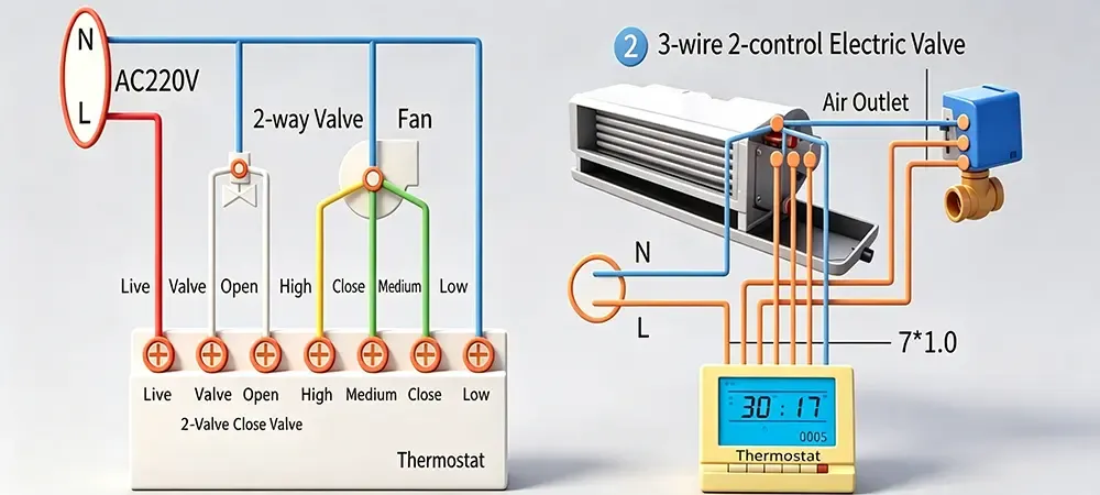
The Wiring Principle of Fan Coil Unit control circuits is where many HVAC installation mistakes originate. A clear wiring diagram for a 2 pipe FCU typically involves two distinct circuits: the fan speed selection loop and the motorized valve actuation loop. Understanding both is non-negotiable for reliable commissioning.
Two-Wire Valve Control (Single-Action)
In the two-wire configuration, the motorized valve has only two control leads: one connects to the thermostat's "Live" terminal, the other to the "Valve Open" terminal. When the thermostat calls for cooling or heating, it energizes the valve — a spring-return mechanism closes it upon power loss. This is the most common wiring diagram approach for budget-sensitive 2 pipe FCU installations.
Valve terminals: Live (L) + Valve Open (VO) — 2 wires total
Fan speed taps: High / Medium / Low — each connects to corresponding thermostat terminal
Neutral: Shared across fan motor and valve actuator
Fail-safe: Power loss = valve spring-returns to closed position
Three-Wire Valve Control (Double-Action)
A more robust alternative uses three control wires: Open / Close / Common. The thermostat sends discrete open and close signals, and the valve actuator drives in both directions. Compared to the two-wire version, this wiring diagram configuration reduces valve hunting and extends actuator life. Deiiang™ field data from Jason Peng's product testing indicates a 40% lower failure rate over a 5-year period for three-wire valve actuators versus two-wire types in 2 pipe fan coil unit applications with frequent cycling.
Valve terminals: Open (O) + Close (C) + Common (COM) — 3 wires total
Control logic: Thermostat pulses O or C independently; no spring return needed
Reliability gain: ~40% fewer field failures over 5 years vs. 2-wire
Pro Tip: Always verify the wiring diagram printed on the junction box cover of your 2 pipe FCU before making any connections. A miswired valve — where the "Open" lead lands on the "Close" terminal — can cause the valve to fight the thermostat signal, leading to erratic room temperature swings of ±3°F to ±5°F and premature actuator burnout within 6–12 months.
Why Bottom-Supply Top-Return? The Critical Design Logic
The bottom-supply top-return configuration is not an afterthought. It is part of a deliberate design decision that takes into account fluid dynamICs, thermodynamics, and maintenance. Reversing this to top-supply bottom-return is one of the most common HVAC installation mistakes that are encountered during the commissioning of 2 pipe FCUs. The consequences of such errors are immediate and last for a long time.
Air Elimination & Air Lock Prevention
Air is lighter than water. This fundamental physical property affects any water filled circuit. Air in the form of bubbles will rise in such a circuit. Using a bottom supply top return 2 pipe fan coil unit, naturally any air that enters the unit will rise to the top return connection, where it can be carried off to the main riser's automatic air vent. Inverting the above described 2 pipe fan coil unit to a top supply bottom return would result in the above described air lock, becoming trapped in the upper header and U-bends on top of the fan coil unit.
It's only necessary for a small portion of the water in the circuit to be in the form of air – typically 15% to 20% of the volume of the water in the water filled parts of the system – for the air to have a very significant effect on the performance of the system. Indeed, a single air lock in a 2 pipe fan coil unit, for example, could reduce the effective heat transfer area of the unit's fins by as much as 25% to 35%. Thus, a unit rated for 12,000 BTU/hr of sensible cooling would, with an air locks occupying 15% to 20% of the volume of the water in the upper water filled parts of the system, deliver only about 8,400 BTU/hr. This is a reduction of 30% in the cooling capacity of the unit, which would not be affected by attempts to increase the cooling by raising the thermostat.
Uniform Heat Exchange & Flooded Coil Condition
Water entering from the bottom of the coil rises slowly and uniformly, filling each tube pass completely before overflowing to the next. This flooded condition ensures every inch of copper tube wall is wetted and participating in heat exchange. The heat transfer coefficient h for the water-side convection can be estimated using the Dittus-Boelter correlation:
Nu = 0.023 × Re0.8 × Pr0.4 → h = (Nu × k) / Dh
Where Re (Reynolds number) depends directly on flow velocity through the fully wetted tube cross-section. A partially filled tube — as occurs with top-supply configurations — reduces the effective hydraulic diameter Dh and creates stagnant zones, dropping the average h value by 20–30%. This explains why a reversed 2 pipe fan coil unit connection can reduce overall heat exchange capacity by approximately 30% compared to the correct bottom-supply top-return orientation.
Service Accessibility & Condensate Protection
With the supply piping and Y-strainer positioned below the unit, maintenance personnel can access the strainer for routine cleaning without working above their heads or risking condensate drips onto electrical components. The motorized valve, installed on the upper return pipe, stays dry even if the condensate pan overflows — a common occurrence when drain lines clog. Placing the valve below the unit (as some misguided HVAC installation mistakes dictate) exposes the actuator to water damage, leading to a 60–80% higher probability of valve failure within the first two years according to Deiiang™ warranty return analysis.
Performance Impact: Correct vs. Reversed Piping (12,000 BTU/hr 2-pipe FCU)
Bottom-Supply Top-Return (Correct) — Capacity Retention
Top-Supply Bottom-Return (Reversed) — Capacity Retention
Summary: Getting the Two-Pipe FCU Right
The two pipe fan coil unit can appear to be a simple product to show on a submittal drawing. In reality, however, careful attention to the construction details, the piping in sequence, the wiring, and most importantly, the bottom supply top return flow orientation is required to achieve satisfactory performance. Data from thousands of field installations shows that units that are correctly piped and wired from the start will experience 70% fewer service calls over a 10 year period compared to similar units with minor deviations.
Ceiling leaks, inadequate cooling, abnormally loud motor hums, and other problems with thermostats can be traced back to reversed piping connections, or problems with HVAC installation mistakes, including mistakes in the wiring diagram. By following the guidelines set forth in this paper for a 2 pipe FCU installation (bottom supply, top return, correct valve configuration, and clean strainers) you can count on a comfortable and reliable system. Deiiang's continued design improvements to the 2 pipe fan coil units are under the engineering direction of Jason Peng, and are intended to further make the units easy to install and to service, based on feedback from in the field.
Deiiang™ Case Studies — Two-Pipe FCU Applications
The following template cases illustrate how Deiiang™ 2 pipe FCU solutions have been deployed in real-world scenarios.
Case 1 — Commercial Office Retrofit, Chicago IL
Project Overview: 12-story office tower, floors 4–8 retrofit with 140 units of 2 pipe fan coil unit replacements. iso class 8 clean corridor on floor 6 for Pharmaceutical storage. Total area: 28,000 sq ft
Challenge: Existing top-supply bottom-return piping caused persistent air locks; measured capacity loss averaged 32% across 40 sampled units. Condensate overflow incidents reported 8 times in 18 months
Deiiang™ Solution: Re-piped all units to bottom-supply top-return with Deiiang™ DF Series 2 pipe FCU models featuring integrated Y-strainer access panels. Three-wire valve control adopted per Jason Peng's recommended wiring diagram spec. Installation overseen by Deiiang field engineers.
Results: Post-retrofit capacity recovery to 94% of rated output. Zero condensate incidents in 24 months post-completion. Energy savings estimated at $18,000/year from reduced pump head and improved ΔT.
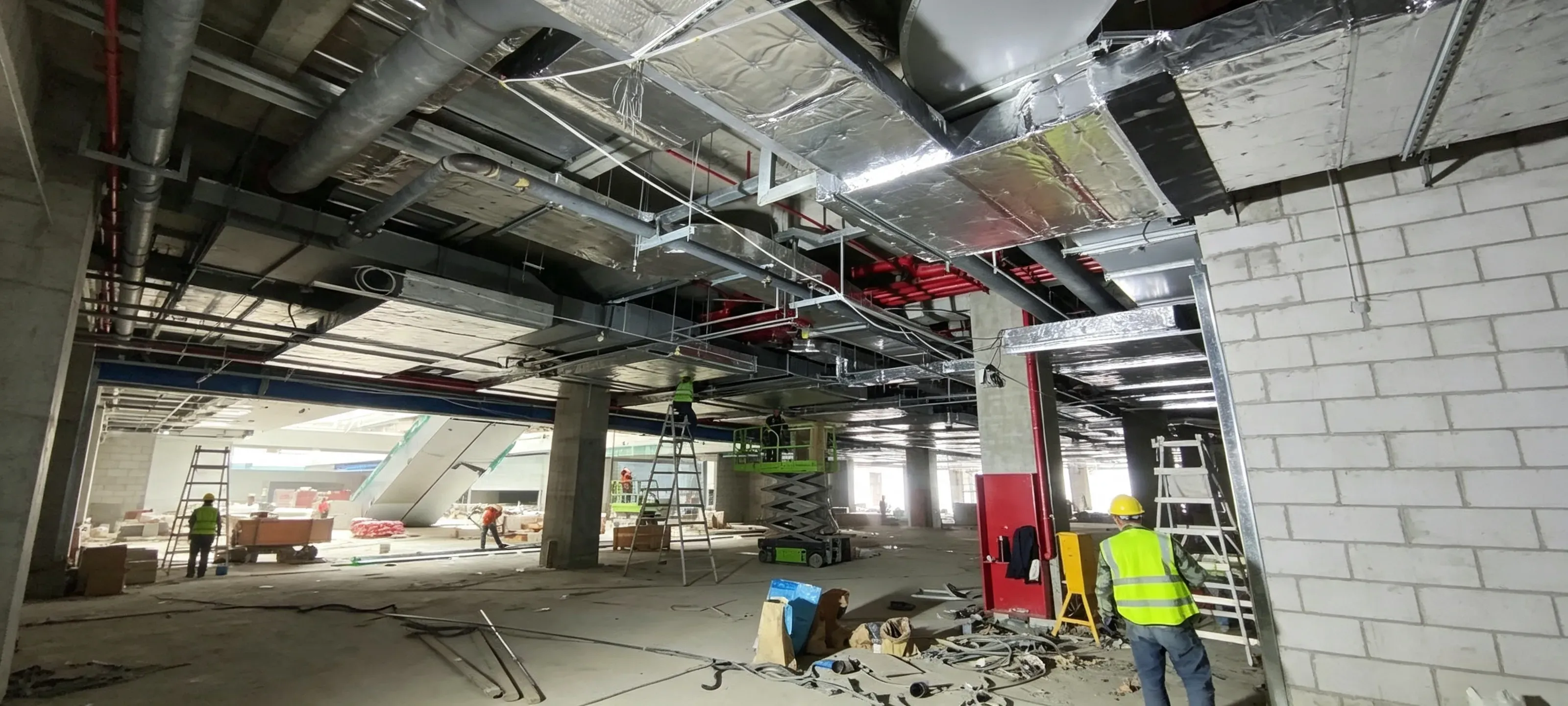
Case 2 — Hotel Guestroom FCU Upgrade, Orlando FL
Project Overview: 220-room resort hotel, 2 pipe fan coil unit replacement during off-season. High humidity environment (design dew point 78°F).
Challenge: Existing units suffered condensate mold growth due to inadequate drain pan slope. Guest complaints about "musty odor" averaged 15 per month
Deiiang™ Solution: Deiiang™ DH Series 2 pipe FCU with antimicrobial drain pan coating and enhanced 1:75 internal slope (exceeding ASHRAE minimum). P-trap depth calculated per unit static pressure: Trap depth = 2 × 0.75 in. w.c. + 1 in. = 2.5 inches.
Results: Guest odor complaints dropped to 1 per quarter. Drain pan inspection at 12-month mark showed zero mold colonies in sampled units.
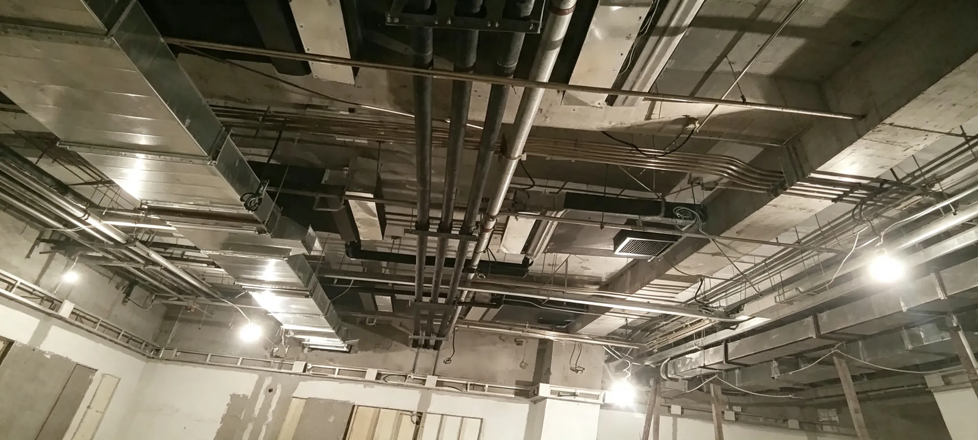
Case 3 — cleanroom Ancillary Office, San Francisco CA
Project Overview: Biotech facility ancillary office adjacent to iso 7 cleanroom. Required 2 pipe FCU with low-VOC materials and cleanable surfaces. Area: 1,800 sq ft.
Challenge: Standard FCU insulation emitted particulates unacceptable for proximity to cleanroom. Need for accessible wiring diagram documentation for FDA audit trail.
Deiiang™ Solution: Deiiang™ CL Series 2 pipe fan coil unit with closed-cell elastomeric insulation (VOC <50 µg/m³), stainless steel drain pan, and QR-coded junction box linking to digital wiring diagram archives. Design validated by Jason Peng's product engineering team.
Results: Passed iso 14644-1 Class 7 particulate testing at 0.5 µm. Audit documentation approved within 48 hours.
User Persona — Who Benefits Most from This Guide
To ground this technical discussion, consider a representative user profile drawn from Deiiang™'s client base:
PERSONA
Name: Michael Rodriguez — Facilities Manager at a mid-sized Pharmaceutical manufacturing plant in New Jersey.
Pain Points: Oversees 300+ 2 pipe FCU units across office and cleanroom support zones. Annual HVAC service budget of $120,000, with 35% currently consumed by reactive repairs from HVAC installation mistakes made during previous renovations.
Decision Drivers: Compliance (FDA 21 CFR Part 211 for environmental control), total lifecycle cost (not just first cost), and ease of maintenance documentation for regulatory audits.
Desired Outcome: Reduce FCU-related service calls by 50% over 3 years, standardize on a single 2 pipe fan coil unit specification with clear wiring diagram standards, and ensure all new installations follow bottom-supply top-return piping without exception.
Acceptance Criteria: Post-installation capacity verification within ±5% of submittal data; zero condensate leaks within first 12 months; documented 3-year total cost of ownership below $850 per unit including maintenance labor and parts.
Micro-Glossary — Key Terms
TERM
2 Pipe FCU / Two Pipe Fan Coil Unit: A terminal air-conditioning unit with a single coil served by two water pipes (one supply, one return), capable of either heating or cooling but not both simultaneously. The most common FCU configuration in US commercial buildings with seasonal changeover.
TERM
Bottom-Supply Top-Return: A piping arrangement where chilled or heated water enters the coil from the lower connection and exits from the upper connection. This orientation leverages natural buoyancy for air removal and ensures a fully flooded coil condition for optimal heat transfer.
TERM
Air Lock: A trapped pocket of air within a hydronic coil or pipe that obstructs water flow, dramatically reducing heat exchange capacity. Air locks in FCU coils can reduce output by 25–35% and are a primary symptom of incorrect top-supply bottom-return piping.
TERM
Y-Strainer: A Y-shaped inline filter device installed on the supply side of an FCU to capture debris and protect the coil and valve from clogging. Typical mesh size ranges from 20 (coarse) to 40 (fine), and cleaning interval should not exceed 6 months in typical commercial duty.
TERM
Motorized 2-Way Valve: An electrically actuated on/off or modulating valve installed on the return side of an FCU to control water flow in response to thermostat demand. Available in two-wire (spring-return) and three-wire (powered open/close) configurations.
Conclusion & Next Steps
Selecting and installing a two pipe fan coil unit is not merely about matching a catalog number to a schedule. It demands an integrated understanding of structural principles, piping logic, wiring accuracy, and the non-negotiable bottom-supply top-return flow path. When these elements align — as validated by Deiiang™ engineering and Jason Peng's product designs — the result is a system that delivers rated capacity, resists air locks, drains condensate reliably, and minimizes maintenance over its service life.
For facility managers like Michael Rodriguez and the broader US HVAC community, the message is clear: invest in correct installation up front. The cost of re-piping a single reversed 2 pipe FCU can exceed $1,500 in labor and materials — far more than the incremental cost of getting it right the first time.
"In HVAC, firestopping must protect both life safety and product integrity — choose materials that meet fire, smoke, and cleanliness demands simultaneously. The same philosophy applies to FCU design: every connection, every orientation, and every component must serve both performance and longevity." — Jason Peng, Lead Product Designer, Deiiang™
Ready to specify or troubleshoot your FCU installation? Contact Deiiang™ for a 2 pipe fan coil unit consultation, request a detailed wiring diagram package, or download our technical data sheets at www.deiiang.com. Our US-based support team can assist with submittal reviews, on-site assessments, and customized training for your installation crews.
References
ASHRAE Handbook — HVAC Systems and Equipment, Chapter 5: "Room Air Distribution Equipment" — ashrae.org
UL 1479 — Standard for Fire Tests of Through-Penetration Firestops — ul.org
ASTM E814 — Standard Test Method for Fire Tests of Penetration Firestop Systems — astm.org
NFPA 101 — Life Safety Code — nfpa.org
FDA 21 CFR Part 211 — Current Good Manufacturing Practice for Finished Pharmaceuticals — fda.gov
ISO 14644-1 — cleanrooms and Associated Controlled Environments — iso.org
© 2026 Deiiang™ — All rights reserved. | Product design: Jason Peng | This article contains template case studies with placeholder data; actual project results may vary. Always consult local building codes and a licensed professional engineer for project-specific guidance.