+86 18186671616
 Jason@cleanroomequips.com


 MENU

We can find six essential clauses, real seal data and speed data collected from our door platform at Deiiang, a FAT piloting checklist, and another retrofit case here. Other than the open numbers, all items mentioned have not been published, and this is their purpose. We see the same pattern time and again for vaccine and biopharma in the underdeveloped market of South and Southeast Asia. The difference will not stay true, and the root of the issue is in the door, not the HVAC requirements.
If you ask any cleanroom HVAC engineer on how the QA works today, following the Annex 1 changes in 2022, they will tell you more about doors than about HEPA cabinets. In this guide, I would like you to see how the gmp annex 1 door design works in real life. Having done cleanroom and HVAC projects for over 15 years, and equipped laboratories and pharmaceutical plants in various countries for the latest 10 years, I can assure you that most failed audit cases are accompanied by doors, disguised as the airflow issues.
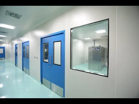
Regulatory Context and Scope
Impact of Annex 1 Revision on Door Design
The revision for 2022 changed cleanroom doors from a finishing trade to a controlled system. Contamination control is now risk-based, meaning that pressure has to hold under all operating conditions, cleanability is ACHieved through design, and airflow visualization leaves a video record. The same pressure-direction concept applies globally (ex. WHO TRS 981: Annex 6 [10] states that this apply specifically for sterile products).
Refer to the EU GMP Annex 1 door compliance checklist (PDF) that we give to QA at the beginning of the project. Based on our experience, the clause that clients miss first is documenting their justification to allow CCS delay:
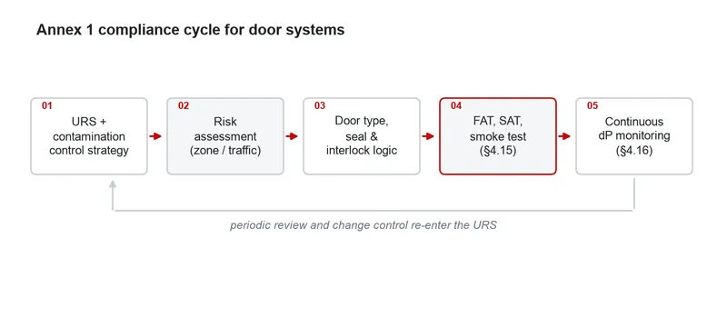
Figure 1. Annex 1 compliance cycle for door systems.
Defining Cleanroom Door Scope and Classification
Annex 1 has set guidelines for the proper performance and working mechanisms and does not provide any model specifications. Classify each entrance according to the zone (A-D Grades), traffic type (personnel airlock, material airlock, pass-through hatch) and their purpose (normal, egress, impact, and high-frequent logistic traffic). The confusion caused by combining grade classification with iso classes should always be avoided by having the class maps at hand:
| EU gmp grade | iso 14644-1 class | Typical area |
|---|---|---|
| Grade A | iso 5 | Critical filling / opening zone |
| Grade B | ISO 5 at rest, ISO 7 in operation | Background to Grade A |
| Grade C | ISO 7 at rest, iso 8 in operation | Supporting cleanrooms |
| Grade D | ISO 8 at rest | Washing / preparation rooms |
Grade and ISO 14644-1 class mapping.
The requirements for door sealing and interlocking system all depend on the appointed zone grade but not a model of the door. All design in China is done on the base of GB 50457-2019 while the construction acceptance – GB 50591-2010.[15].
Our engineers have gate model types organized in the Deiiang selection matrix (PDF): type A/B airlocks are with airtight automatic sliding doors (1200/1500 x 2100 mm, anti-pinch); types C/D airlocks with coated steel doors (900/1200/1500 x 2100 mm); high-speed roll-up doors are used for material transfer; and egress doors are of steel based models with screw type panic hardware of 304 stainless steel. My recommendation is to always use the zone for selection and then approach the model choice.
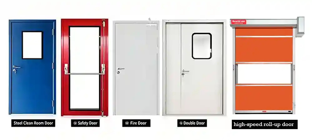
Figure 2. Door type mapped by grade and traffic category.
Fundamental Design Parameters
Achieving Required Pressure Differentials
In accordance with subsection 4.14 of EU GMP Annex 1, the two adjoining zones of various cleanliness categories are to maintain a minimum pressure difference of 10 Pa. This is to be verified using a micromanometer with both doors closed on the cleanroom airlock. The problem of door leakage is a function of the pressure recovery time after a door is opened. In practice, this has been demonstrated by previous studies using the air-change pattern in the room and the area of the opening as opposed to the speed of the door as specified by the manufacturer.
The pressure and leakage characteristics of the system are provided in the PDF titled “Pressure and Leakage Characteristics of Deiiang Cleanroom Doors.” A finished cleanroom door is produced using a sandwich construction with a three-sided rubber/plastic gaskets as well as a drop down automatic brush. In practice, an evaluation has shown that the actual pressure and leakage number cannot be found by regulatory means. The URS value must be determined with the knowledge that in nine out of ten cases the seal failure is due to the condition of the substrate floor, rather than the door itself. Use a 2 m straightedge to assess the floor condition.
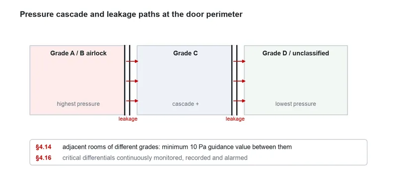
Figure 3. Leakage paths at the threshold and gasket edges.
Seal Efficiency and Particle Contamination Control
A seal system is only as good as its worst edge. You would be surprised how many leaves pass a booth leak test and then bleed at the bottom, because the epoxy floor is not as flat as the drawing assumed. Select profiles, materials and cleaning compatibility together, not separately.
| Door system requirement | Annex 1 basis | Verification evidence | Checked at |
|---|---|---|---|
| Minimum 10 Pa between different grades, all states | §4.14 [1] | Micromanometer log, doors closed | PQ / periodic |
| Key differentials continuously monitored, recorded, alarmed | §4.16 [1] | Trend report + alarm delay justification in CCS | OQ & PQ |
| Airlock doors not opening at the same time | §4.13 [1] | Interlock sequence test, both directions | FAT / OQ |
| C/D airlock visual/audible warning minimum | §4.13 [1] | Warning device function test | OQ |
| Airflow visualized, static + dynamic, video archived | §4.15 [1] | Smoke-test video in validation report | PQ |
| Grade A/B observable from outside | §4.17 [1] | Vision panel or camera sighting check | SAT |
Basis: §4.14
Evidence: Micromanometer log, doors closed
Checked: PQ / periodic
Basis: §4.16
Evidence: Trend report, CCS delay justification
Checked: OQ & PQ
Basis: §4.13
Evidence: Interlock sequence test
Checked: FAT / OQ
Basis: §4.13
Evidence: Warning function test
Checked: OQ
Basis: §4.15
Evidence: Archived smoke-test video
Checked: PQ
Basis: §4.17
Evidence: Sighting check
Checked: SAT
Table 1. Door system requirements mapped to Annex 1 clauses and the acceptance evidence QA will ask for.
gasket and sealing geometry are detailed in the Deiiang door gasket and sealing detail (PDF). Gaskets are wear-resistant, anti-ageing rubber-plastic, auto glue-dispensed; vision panel is double tempered glass with a 20 mm black or white silkscreen border, flush with the leaf; leaf thickness 50 mm. What I check first: does the bottom sweep have adjustable travel for floor tolerance — if not, send it back.
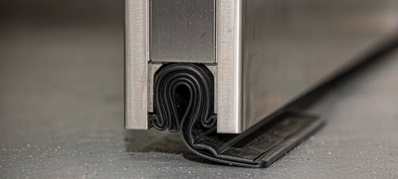
Figure 4. Three-side gasket plus drop-down bottom sweep.
Airflow and Interlock Control
Airlock Interlocking Logic and Timing
Construct the control logic in four tiers: door-position signal, interlocking device controllers (i.e. PLCs/dedicated door controllers), emergency release mechanisms, and logging-enabled BMS alarms. Compliance with International Organization for Standardization (ISO) 14644-5 standards is mandatory. One rule guarantees inspectors’ peace of mind - egress is always prioritized over interlock safety. Extended time delays are unnecessary because an operator will simply use a foot to block the door open, rendering the interlock moot [1]. Establish values based on user requirement specifications (URS) and provide rationale in compliance configuration documents (CCS); never duplicate designs from other facilities. If seeking quotes for Grade B airlocks, request interlock wiring diagrams from electrical contractors prior to installing wall panels.
- Door-magnet confirms leaf A shut; leaf B release then energizes.
- Set a closing-to-opening time delay; justify its length in the CCS.
- Power-fail or fire signal releases both leaves, event logged.
- BMS trends false attempts, alarms and delay violations.
the wiring layout is comprised of the Deiiang airlock interlock control diagram (PDF): fingerprint lock; motion sensing switch; concealed electronic interlock device; foot sensor leveraged against stainless steel composite lever, compression locks, panic device exit assembly; concealed closes or starters available. It is our normal practice to reject any quote on an airlock without a failure mode analysis.Additionally, we have developed THIS .
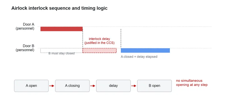
Figure 5. Interlock sequence with egress override branch.
Minimizing Turbulence During Door Operation
According to EU GMP Annex 1 §4.15, the airflow must be evaluated in both static and dynamic phases and documented on tape. Measurement techniques are done in accordance with iso 14644-3 standards. CFD is fine as far as design comparisons go during the concept phase, but the actual method of measuring approval is on-site smoke analysis combined with differential tracing which is a regular finding in the design audit process. Don’t give the reviewer your CFD results and call that substantive documentation.
| Check item | Why it matters | Verified by |
|---|---|---|
| Opening and closing speed adjustable | Shorter open time = smaller pressure dip | Controller settings log |
| Leaf dwell time minimized after pass-through | Held-open doors defeat the 10 Pa gradient | Stopwatch + trend record |
| Doorway sized to real traffic, not oversized | Opening area scales the disturbance | URS / door schedule review |
| AHU / VAV response matched to opening cycle | Recovery time depends on supply-air margin | Differential recovery trace |
| Smoke test static + dynamic, video archived | §4.15 evidence requirement | Video file in validation report |
| Recovered differential before re-entry | Confirms no reversal during transit | Micromanometer reading |
Why: Shorter open time = smaller pressure dip
Verified by: Controller settings log
Why: Held-open doors defeat the gradient
Verified by: Stopwatch + trend record
Why: Area scales the disturbance
Verified by: URS / schedule review
Why: Recovery depends on supply margin
Verified by: Differential recovery trace
Why: §4.15 evidence
Verified by: Video in validation report
Why: No reversal during transit
Verified by: Micromanometer reading
Table 2. Door-opening air disturbance control checklist, taken to the site walkdown.
Details about opening action measurement can be found in the Delannoud study on airway opening actions. Opening speed of the high-speed roll-up doors range from 0.8 to 1.2 meters per second and that of closing speed is fixed at 0.6 to 1.0 meters per second, both speeds adjustable. The GONICE curtain doors close at a speed of 1.2 m/s whereas sliding automatic doors are controlled by microprocessors which can be configured for speed and time. Our tuning technique is as follows: set the closing speed last because a too fast closing speed will strike the air barrier too hard, while a speed slower than normal will leave an opening.
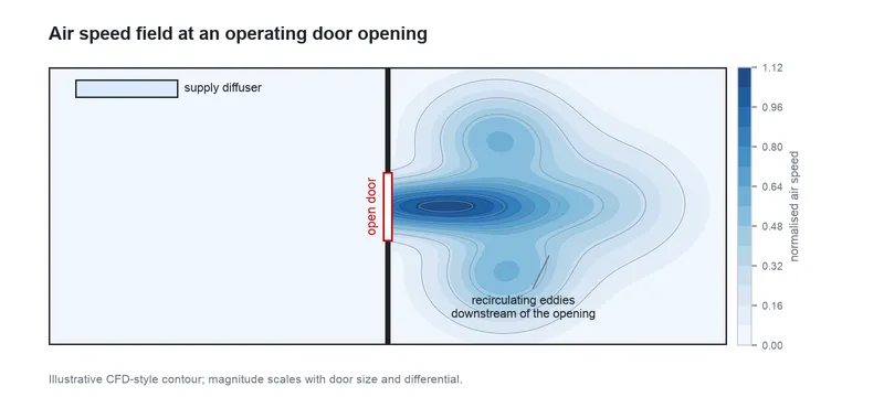
Figure 6. CFD contour near the operating door plane.
Door Structure and Selection
Selecting Door Materials and Finishes
There is a place for the use of coated galvanized steel as well as for 304 / 316L stainless. Make the choice based on the compatibility of your disinfector and VHP, and not from glossy showroom finishes. In accordance with USP <797>/<800>, similar surfaces must be used in compounding suites which are non-shedding and compatible with disinfectants. Annex 1 did not specify that it must be 316L; Ra values regarding surface roughness are used for internal purposes only. As a rule in the field, we provide the following: the edges of coated panels that are cut on site without touch-up painting will rust the fastest in the new plant. The panels should be pre-cut to the measured openings at the factory.
For a complete comparison of the specifications regarding pharmaceutical-grade doors, please see the Deiiang pharmaceutical-grade doors material specification (PDF). Coated doors consist of 1.2mm frame/0.8mm door made up of galvanized steel, either a powder or fluorocarbon finish, with cores made up of paper honeycomb, fireproof aluminum honeycomb, or rockwool; the impact door made of 304 stainless steel has a 1.2mm leaf with satin finish.
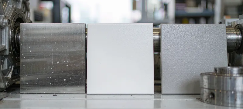
Figure 7. Surface finish comparison under wipe testing.
Mechanical Structure for Different Cleanliness Grades
A flush frame will allow the omission of the ledge collecting dust. The Centre-T aluminum profiles connect the structure to 50–100 mm sandwich panel walls on both sides of the door frame. With the same application of flush and the omission of hardware protrusions, machine- and hand-fashioned approaches call for different connectors.
The drawings in the mounting section are based on the Deiiang flush door mounting detail (PDF). These doors can be employed on walls of 50, 75, or 100 mm sandwich today; they may also be utilized on masonry. Such double-glazed vision panels as 400 × 600 mm or 600 × 400 mm are compatible; the clean windows can include 1.0 mm aluminum frame and 5 mm × 2 mm glazing. The catch is that the wall builder, not the door order, determines the type of panel being used.
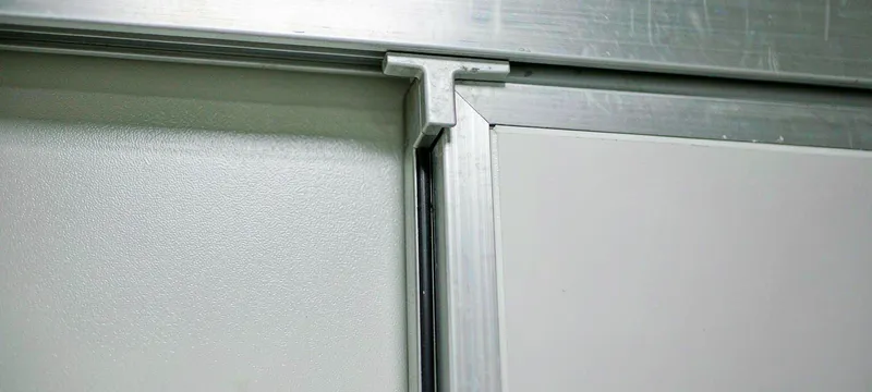
Figure 8. Flush frame-to-wall section detail.
Qualification and Inspection
Validation Protocols for Door Integrity
The aforementioned system should be treated as a system with respect to EU GMP Annex 15 methodology including URS/DQ, IQ, OQ, PQ [2].Furthermore, product performance has been documented according to EN 14351-1 [9]. It also helps to remember a rule about wiring: fire alarms must be hard-wired into interlock loop — this rule should never be violated as if only software is used, release will be hindered in case of power loss.
- FAT: dimensions, leaf flatness, gasket contact, hardware action, interlock simulation.
- SAT / IQ: frame perpendicularity, flushness to wall, gasket seating, sweep landing.
- OQ: interlock logic, alarm, delay, emergency release, power-fail operation.
- PQ: differential and smoke test under dynamic traffic.
Our systematic approach of conducting the Deiiang cleanroom door FAT/SAT protocol (PDF) consists of determining pass/fail criteria based on your project URS at kickoff. Our norm is to run the interlock simulation two times, with the first time being on battery backup — the precise state QA inquires about during the walkdown.
When you request a quotation, ask the door supplier for five documents:
- Leaf thickness and core material datasheet
- Gasket material list with disinfector compatibility (VHP / quaternary ammonium / peracetic acid)
- Interlock control schematic with failure-mode description
- FAT / SAT report template
- Surface finish and seal-warranty duration
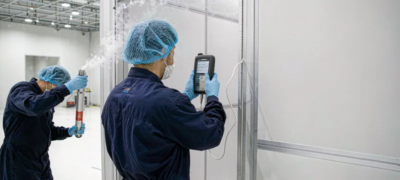
Figure 9. On-site leakage and differential measurement.
Periodic Self-Inspection Checklists
An installed door degrades quietly. Seal rubber hardens, bottom sweeps settle, door closers drift. A short quarterly walkdown catches most of it before QA does:
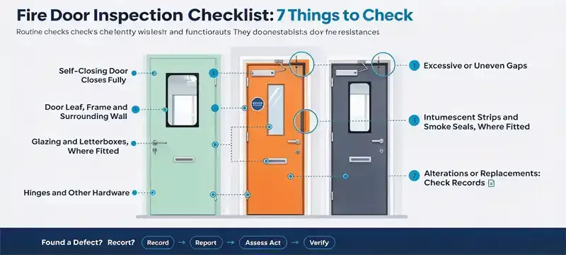
Figure 10. Periodic inspection points on a door leaf.
Common Misconceptions
Busting Common Design Myths
Walk into any mechanical room and you will hear the same four habits repeated. Each one below has cost a project an extra OQ cycle at some plant we know.
“Higher pressure is always better.”
FACT: Per §4.14, 10 Pa is a guidance minimum, not a target to chase upward [1]. Oversized differentials waste energy and make leaves hard to push — so operators prop them open.
“Automatic doors are unnecessary in cleanrooms.”
FACT: Annex 1 never mandates automation. What §4.13 mandates is controlled sequencing at airlocks [1]; automatic sliding doors are the practical way to hold it at high-traffic Grade A/B.
“Material doesn't matter if the finish looks clean.”
FACT: Material is selected by compatibility with your cleaner, disinfector and VHP cycle. Per iso 14644-4, surfaces must be smooth, non-shedding and compatible with the URS cleaning regime [5].
“Seal maintenance is optional if doors are rarely used.”
FACT: Sweeps settle and rubber harden with age, not cycles. Frequency follows your SOP; under Annex 15 the program and its evidence are reviewed [2].
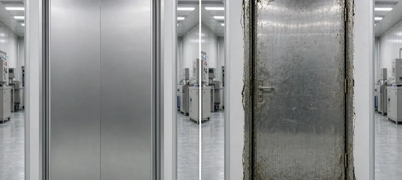
Figure 11. Proper detail versus poor detail at the same opening.
Critical Errors in Hardware Specifications
Hardware is where budgets get trimmed and audits get surprised. The product designer here says the single most common field mistake he sees is swapping in standard non-cleanroom hinges because the catalog item was out of stock.
| Specification error | Why it fails on site | Correct practice | Basis |
|---|---|---|---|
| Standard non-cleanroom hinges | Screw heads and accumulation points break the cleanable surface | Detachable or concealed 304 stainless hinges, flush hardware | ISO 14644-4 design principles [5] |
| Misadjusted door closer | Leaf never seats the gasket; slam wears the sweep early | Closer sized and adjusted to leaf mass, hold-open disabled in Grade A/B | Per project URS |
| Wrong handle material | Carbon steel levers rust under daily disinfection | 304 stainless split lever, integrated lever or compression latch | Per project URS |
| Egress compliance neglected | Interlock overrides escape routes; fire marshal stops the project | Panic exit device on required leaves; egress overrides interlock | NFPA 101 life safety provisions [11] |
Why it fails: Screw heads, dust accumulation
Correct: Detachable/concealed 304 SS hinges
Basis: ISO 14644-4 [5]
Why it fails: Leaf misses gasket; slam wears sweep
Correct: Closer sized to leaf, hold-open off in A/B
Basis: Project URS
Why it fails: Carbon steel rusts under disinfectors
Correct: 304 SS lever / compression latch
Basis: Project URS
Why it fails: Interlock blocks escape routes
Correct: Panic device; egress overrides interlock
Basis: NFPA 101 [11]
Table 3. Critical hardware specification errors versus accepted practice, with the authority behind each correction.
The most common error hidden in Table 3 is treating a cleanroom door as a fire door. Egress routes and openings through fire-rated walls use doors selected and fire-tested per EN 1634-1 [8] — never substitute a cleanroom leaf.
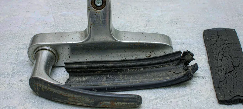
Figure 12. Field-failed hardware after daily disinfection.
Project Case Study
Real-world Cleanroom Door Failure Case
In the warm, humid climate of Vietnam, a sterile injectable filling suite had been equipped with manually-operated swinging doors and gasket seals to separate the grade B area from other areas without an interlock system. Due to extreme temperatures and humidity, the gaskets became ineffective within months, and the operator could not maintain a positive 10 Pa pressure between the airlock and the production area, causing the airflow visualization to fail to meet the criteria defined in the FDA regulations.
As a result, the replacement door constructed for the suite with a new production line consisted of state-of-the-art airtight automatic sliding doors measuring 1200 X 2100 millimeters. Through the use of a differential trend to demonstrate that the 10 Pa positive pressure was maintained, we were able to verify that there was no door malfunction. In most cases, the door problem arises from the floors and the opening tolerances of the automated system. If flatness criterion had not been included in our URS, then everything else would become a patch. If one is constructing/utilizing a floor that has already been poured, it is important to ensure that it meets the specifications outlined before utilizing the bottom sweep technology with the automated sliding doors.
Next, it is important to remember that section 8.123 covers the freezing/loading/unloading areas, and this section is required to be complied with beginning on August 25, 2024. Therefore, the doors utilized for these portions of the freezing/loading area must contain isolates seals to achieve the intended sealing level.
Implementing Optimized Design Solutions
The order of steps in the retrofit process is important, just like the equipment to be used; begin by measuring the tolerance of the floor, then choose the door, then justify the interlock delay in the CCS and finally install continuous monitoring with alarms according to Section 4.16 of the required standard.
Our advice is to choose the door size based on actual traffic and confirm the smoothness of the floor beforehand - in fact, after design reviews, the door schedule should not be considered final. Seven of every ten projects will experience door difficulties during commissioning; it is advised that a process to make corrections after factory acceptance testing is included in contracts with contractors.
Frequently Asked Questions
What is the most significant responsibility of GMP Annex 1 regarding the cleanroom doors?
The Annex accepts door designs as boundaries against contamination rather than architectural features. By requirements of the Annex, no two airlock doors should operate at the same time, Grade A/B areas have to be visible, there have to be alarm signals on key differences, and airflow should be monitored using video systems. In fact, gmp annex 1 door design gives instructions on how to manage pressure flow between the zones in a time of opening.
Are automatic door systems compulsory according to Annex 1 when designing cleanrooms?
No. The term automatic door is never used in the Annex. The only requirement of the document is that airlocks of Grade A/B should be interlocked and airlocks of Grade C/D should provide at least visual or audible warnings. Though automatic sliding doors are the best solution from the engineering point of view for busy Grade A/B airlocks, the use of manual systems is also compliant.
How does door design influence the pressure differentials in cleanrooms?
The appearance of leaks around the leaf due to gaps in sealing systems, too much clearance between the threshold and the door leaf, or too big door openings will result in elimination of the differential created by the air handling unit. According to the requirements of section 4.14 of the Annex, 10 Pa is the minimum level of differential pressure needed for all grades of cleanrooms.
What materials are suitable for cleanroom doors balanced by Annex 1?
The Annex does not regulate the choice of materials. The general principle approved is that coated galvanization is acceptable for Grade C/D cleanrooms, while grades 304 and 316 L are used when the disinfection procedure is being performed. Surface roughness and chemical resistance should be considered in accordance with the user requirement specification.
How often do cleanroom doors have to be checked, according to the requirements of the Annex?
The Annex does not present the intervals for checking the doors. The rules set in annex 15 regarding the qualification of cleanrooms stipulate that periodic checks should be made following the SOP established by the organization, depending on the risk factor. Commonly, there are checks of the gasket, interlock system, and alarm signals on a quarterly basis.
What seal is the most appropriate for grade b cleanrooms?
There is no perfect seal design, which is able to satisfy all types of cleanroom. As a minimum, there must be a three-side seal and drop-down sealing system provided. The sealing material should also be disinfectant-resistant and its design will depend on the kind of traffic and the way of cleaning.
References
- [1] European Commission. EU Guidelines for Good Manufacturing Practice for Sterile Medicinal Products, Annex 1 (2022, in force 25 August 2023; §8.123 applicable from 25 August 2024). health.ec.europa.eu
- [2] European Commission. EudraLex Volume 4, Annex 15: Qualification and Validation. health.ec.europa.eu
- [3] iso 14644-1:2015, Cleanrooms and associated controlled environments — Classification of air cleanliness by particle concentration. iso.org
- [4] iso 14644-3:2019, Design, construction and start-up of cleanrooms — test methods. iso.org
- [5] iso 14644-4:2022, Cleanrooms and associated controlled environments — Design, construction and start-up. iso.org
- [6] iso 14644-5:2004, Cleanrooms and associated controlled environments — Operations. iso.org
- [7] EN 12207:2016, Windows and doors — Air permeability — Classification. European Committee for Standardization. cencenelec.eu
- [8] EN 1634-1:2014, Fire resistance and smoke control tests for door, shutter and openable window assemblies. CEN. cencenelec.eu
- [9] EN 14351-1:2006+A2:2016, Windows and doors — Product standard, performance characteristics. CEN. cencenelec.eu
- [10] WHO Technical Report Series No. 981, Annex 6: WHO good manufacturing practices for sterile pharmaceutical products. who.int
- [11] NFPA 101, Life Safety Code. National Fire Protection Association. nfpa.org
- [12] ISPE Baseline Guide Volume 2: Pharmaceutical Manufacturing Facilities. International Society for Pharmaceutical Engineering. ispe.org
- [13] USP General Chapters <797> and <800>, Pharmaceutical Compounding — Sterile / Hazardous Preparations. United States Pharmacopeia. usp.org
- [14] GB 50457-2019《医药工业洁净厂房设计标准》. 中华人民共和国住房和城乡建设部.
- [15] GB 50591-2010《洁净室施工及验收规范》. 中华人民共和国住房和城乡建设部.
This article is for engineering reference. Final design, acceptance limits and qualification protocols are established against your project URS and the current text of cited regulations.