+86 13638632902
 Jason@cleanroomequips.com


 MENU
MENU
Fireproofing: Use A2‑s1,d0 (EN 13501) or Class A (UL 723) lining. Sealants must be low‑VOC and retain >90 % elasticity after 10 000 h.
Sealing: Plenum leakage ≤1 % at +15 Pa. Perimeter joints ≤0.5 L/(s·m²) with continuous gasket and neutral‑cure silicone.
Performance: For ISO 5, design ffus for 0.45 ± 0.05 m/s. Ceiling deflection ≤L/500, post‑load settlement ≤3 mm.
A cleanroom ceiling system relies on a secondary steel conversion layer, T‑bar ceiling grid, FFU installation and blind panel sealing. This article covers the complete workflow, fire‑compliance and real‑world Deiiang™ case data.
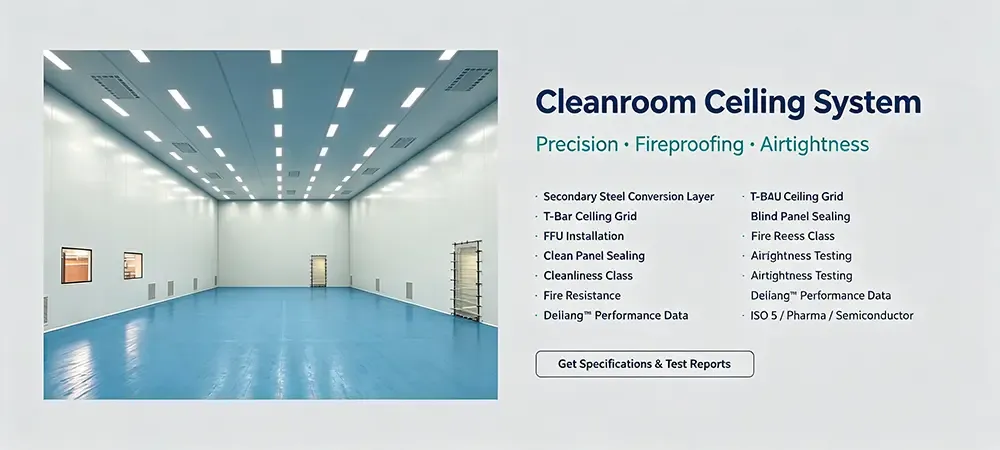
Typical cleanroom ceiling build section
Get specifications & request fire/leakage test reports
Download Spec Sheets Request On‑Site ConsultationCleanroom Fireproofing: Standards & Ceiling Construction Essentials
A cleanroom ceiling system must satisfy three fire‑performance criteria simultaneously: structural fire resistance, low smoke toxicity, and zero flaming droplet formation. The secondary steel conversion layer bears the full suspended load.
The T‑bar ceiling grid frames panels and FFU openings. Perimeter detailing around FFU installation cutouts and blind panel sealing joints must preserve the fire barrier's continuity.
US: NFPA 101 §8.2, NFPA 90A, UL 723 (ASTM E84) Class A, FM 4880/4882 for cavity fire growth
EU: EN 13501‑1 A2‑s1,d0 target; CE Declaration of Performance (DoP) required
CN: GB 50016 (Building Fire Protection), GB 50222 (Interior Finish), GB 8624 A2‑s1,d0
Target indicators: Fire resistance rating per local code (typically 60–120 min for structural elements), smoke development index SDI ≤25, no flaming droplets (d0), and cleanroom‑compatible low‑VOC off‑gassing ≤50 µg/m³.
Fireproofing Materials: Comparison & Selection
Material choice in a cleanroom ceiling system drives both fire compliance and long‑term particulate control. Three common ceiling‑grade options are evaluated below.
| Material | Fire Rating (Typical) | Certification | Suitable iso class | Notes |
|---|---|---|---|---|
| Aluminum Honeycomb Panel | EN A2‑s1,d0 | CE / DoP | ISO 5–8 | Low self‑weight; requires edge sealing |
| Steel Panel (Baked Enamel) | UL 723 Class A | UL / GB 8624 | ISO 6–8 | High impact resistance; verify cleanroom‑grade coating |
| Calcium Silicate Board | EN A1 | CE | ISO 7–8 | Easy to mACHine; strict dust control needed |
| Material | Fire Rating | Best For |
|---|---|---|
| Aluminum Honeycomb | EN A2‑s1,d0 | ISO 5–8, lightweight |
| Steel (Baked Enamel) | UL 723 Class A | ISO 6–8, impact zones |
| Calcium Silicate | EN A1 | ISO 7–8, cost‑sensitive |
Material Comparison: Cold‑Rolled Steel vs. Aluminum
Selecting the right material for your T‑bar ceiling grid impacts weight, corrosion resistance, and overall cost. The table below summarizes key differences.
| Property | Cold‑Rolled Steel (Galvanized) | Aluminum (Anodized) |
|---|---|---|
| Weight | Higher (~7 850 kg/m³) | Lower (~2 700 kg/m³) |
| Corrosion Resistance | Good (with galvanizing) | Excellent (natural oxide layer) |
| Cost | Lower initial cost | Higher initial cost |
| Magnetic Properties | Magnetic | Non‑magnetic |
| Typical Application | General cleanrooms, cost‑sensitive projects | Semiconductor, pharmaceutical, high‑humidity zones |
| Property | Steel | Aluminum |
|---|---|---|
| Weight | Higher | Lower |
| Corrosion | Good | Excellent |
| Cost | Lower | Higher |
Material Evaluation: Aluminum Honeycomb Panel (Sample scores — replace with certified test data)
Cleanroom Sealing: From Enclosure to FFU Boundary
The sealing pathway runs from the T‑bar ceiling grid flange, across the blind panel sealing gasket interface, around each FFU installation flange, and along wall perimeter closures. A single leak compromises the entire pressure cascade.
Target & Test: Maintain +10 to +20 Pa differential; ceiling plenum leakage ≤1 % at +15 Pa (per ISO 14644‑3 methodology). Design access ports for PAO/MPPS filter integrity testing at every FFU location.
Sealant Material Protocol:
Continuous EPDM or silicone gasket on all blind panel edges — no breaks, no overlaps
Neutral‑cure silicone or modified silane at perimeter and penetration points
Low‑VOC (<30 g/L), non‑corrosive to aluminum, elongation >300 %
Aged elasticity retention >90 % after 10 000 h (ASTM C719)
Quality control: Check continuity at corners, T‑bar intersections, and FFU cable penetrations. All sealing work must follow a zero‑contamination protocol — no exposed sealant curing in occupied clean zones.
T‑Bar + FFU + Blind Panels: Complete Installation Workflow
This sequence covers the entire cleanroom ceiling system build, from the secondary steel conversion layer through final FFU installation commissioning. Each phase interlocks with the next — rushing any step creates compounding errors downstream.
“Before constructing the transfer layer, a three-dimensional pipeline coordination (M&E) must be completed. Otherwise, blindly hoisting the transfer layer will result in nowhere to place ducts and cable trays later, forcing rework. We have experienced delays of more than two weeks in at least three projects due to neglecting this step.” — Jason Peng, Product Designer, Deiiang™
Phase 1 — Secondary Steel Conversion Layer:
Erect main beams (120×50×5 mm hot‑dip galvanized square tube) along structural direction; place secondary beams (100×50×2.3 mm) perpendicularly.
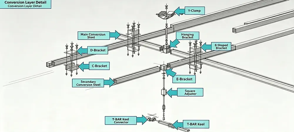
Total dead load (self‑weight of grid + panels + FFUs) must be calculated alongside dynamic live load (FFU start‑up vibration, typically estimated at 15 % of FFU weight). In seismic zones (Zone 3 and above per IBC), diagonal bracing should be added at every third intersection of the secondary steel conversion layer. Deiiang™ engineers apply a safety factor of 1.5× on all suspension points when FFU density exceeds 60 % of ceiling area.Phase 2 — T‑bar Ceiling Grid:
Fine‑level span‑by‑span with rotating laser; single‑span error ≤3 mm; preset 3–5 mm upward pre‑camber to offset blind‑panel + FFU settlement.
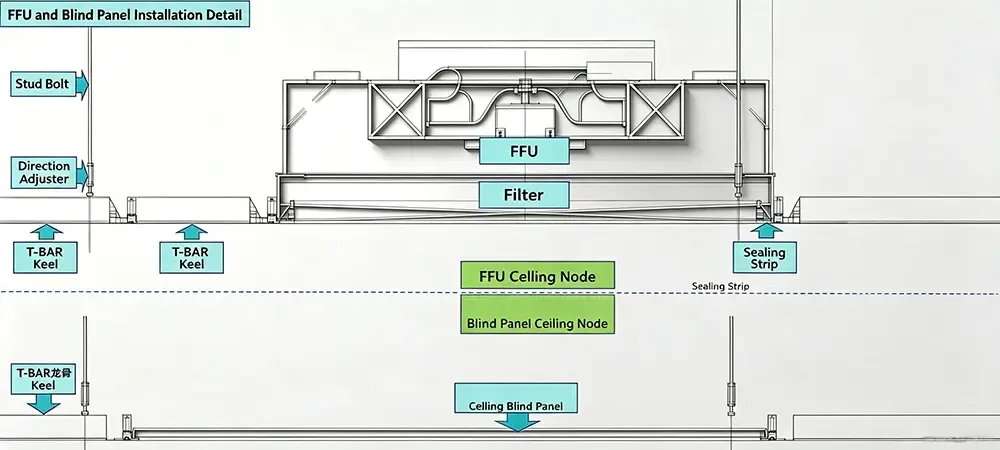
"Many contractors overlook the settlement that occurs after full loading. Without pre‑camber, the ceiling appears visually sunken within weeks, which disrupts laminar airflow uniformity. I've seen this cause a 12 % variance in face velocity at the edges of a 100 m² ISO 5 zone. That 3–5 mm is not optional — it's insurance." — Jason Peng, Product Designer, Deiiang™
Phase 3 — Blind Panels & Sealing:
Verify blind panel sealing integrity — no gaps, no compressed folds, no gasket discontinuity.
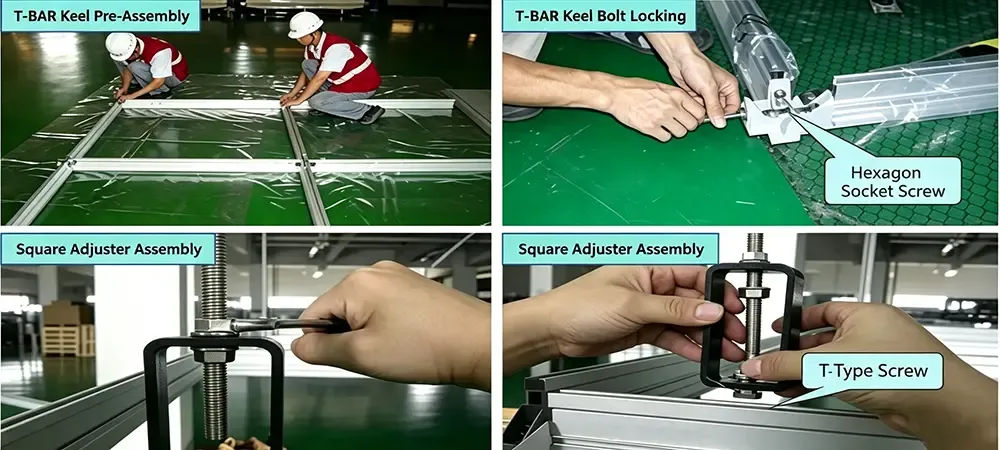
Phase 4 — FFU Installation:
Wire all FFUs; power‑on test — check vibration, airflow uniformity (±10 %), and absence of whistling/leaks.
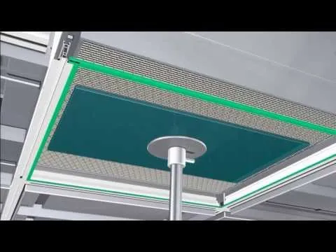
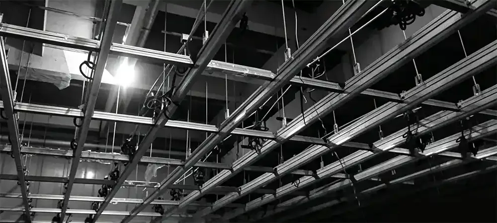
Room‑side replacement allows technicians to change filters from within the cleanroom without breaching the plenum. Top‑side replacement requires access to the ceiling plenum walkway. Deiiang™ FFUs support both configurations; the room‑side option reduces downtime by approximately 40 % because there is no need to evacuate the plenum or re‑balance the entire system after each change.
Maintenance Protocol: Filter Replacement Without Contamination
To maintain ISO class integrity during filter changes, follow this negative‑pressure protocol:
- Pre‑purge: Increase room air change rate by 20% for 30 minutes before access.
- Local exhaust: Position a mobile HEPA‑filtered vacuum hood directly beneath the FFU opening.
- Bag‑in/bag‑out: Use a disposable containment bag to encase the used filter before removal; seal immediately.
- Gasket inspection: Wipe the sealing surface with 70% IPA; replace gasket if any compression set >30% is observed.
- Post‑replacement test: Perform a localized particle count scan and pressure decay test before returning to full operation.
ISO Class Coverage Density: Design Guidelines
FFU coverage density varies dramatically across ISO classes. Over‑specifying leads to unnecessary capital and energy costs; under‑specifying fails validation. The table below provides design benchmarks for standard ceiling heights (2.8–3.2 m).
| ISO Class | Typical FFU Coverage | air changes Per Hour (ACH) | Application Example |
|---|---|---|---|
| ISO 5 (Class 100) | 80–100 % | 300–600 | Aseptic filling, implantable device assembly |
| ISO 6 (Class 1,000) | 40–60 % | 120–300 | Sterile compounding, micro‑electronics packaging |
| ISO 7 (Class 10,000) | 20–40 % | 60–120 | Medical device assembly, buffer zones |
| ISO 8 (Class 100,000) | 10–20 % | 20–60 | Warehousing, secondary packaging, gowning rooms |
| ISO Class | FFU Coverage | ACH Range |
|---|---|---|
| ISO 5 | 80–100 % | 300–600 |
| ISO 6 | 40–60 % | 120–300 |
| ISO 7 | 20–40 % | 60–120 |
| ISO 8 | 10–20 % | 20–60 |
Use these benchmarks as a starting point. Actual FFU count must be verified through computational fluid dynamics (CFD) modelling for critical zones. Deiiang™ provides complimentary CFD validation for projects exceeding 500 m².
FFU Quantity Estimator
Enter your cleanroom area, ceiling height and target ISO class to get a recommended FFU count range and total airflow.
Data & Parameters: Reference Ranges for Cleanroom Ceiling Performance
Use the following values as design benchmarks. Deiiang™ FFU specifications align with these targets; see the product table below for model‑specific data.
| Parameter | Reference Range | Standard / Method |
|---|---|---|
| FFU Face Velocity | 0.45 ± 0.05 m/s (90–110 FPM) | ISO 14644‑3 |
| FFU Noise @ 1m | ≤55 dB(A); Deiiang™ units 55–63 dB(A) per model | ISO 11201 |
| Ceiling Deflection | ≤L/500 under uniform load | EN 1993 / GB 50017 |
| Post‑Load Settlement | ≤3–5 mm (re‑measure after full assembly) | Site verification |
| Pressure Differential | +10 to +20 Pa (clean zone vs. adjacent) | ISO 14644‑4 |
| Ceiling Leakage Rate | ≤1 % @ +15 Pa | ISO 14644‑3 |
| Material Fire Rating | EN 13501 A2‑s1,d0 or UL 723 Class A | Per local AHJ |
| Parameter | Target |
|---|---|
| FFU Face Velocity | 0.45 ± 0.05 m/s |
| FFU Noise | 55–63 dB(A) |
| Ceiling Deflection | ≤L/500 |
| Settlement | ≤3–5 mm |
| Pressure Diff. | +10–20 Pa |
| Leakage Rate | ≤1 % @ +15 Pa |
| Fire Rating | A2‑s1,d0 / Class A |
Testing sequence: Material certificate review → component‑level fire reaction test → cleanroom compatibility (VOC/particle emission) → system‑level leakage test → airflow uniformity scan.
Deiiang™ Product Data & Case Study
The following Deiiang™ product specifications are sourced from current engineering datasheets. All FFU models feature a galvanized steel box, AC fan, and HEPA filtration efficiency of 99.99 % @ 0.3 μm.
Deiiang™ FFU Selection Table (AC Fan Models)
Six standard FFU sizes cover airflow requirements from 500 to 2000 m³/h. Highlighted rows indicate Deiiang™ recommended best‑selling models.
| Size (W×L×H mm) | Air Volume (m³/h) | Fan Model | Power (W) | Weight (kg) | Noise (dB) | Filter Size (mm) | Initial Pressure Loss |
|---|---|---|---|---|---|---|---|
| 575×575×230 | 500 | #315 | 120 | 21 | 55–63 | 570×570×69 | 110 Pa @ 0.45 m/s |
| 615×615×230 | 600 | #400 | 120 | 23.5 | 55–63 | 610×610×69 | 110 Pa @ 0.45 m/s |
| 920×615×230 | 900 | #400 | 120 | 31.5 | 55–63 | 915×610×69 | 110 Pa @ 0.45 m/s |
| 1175×575×230 | 1000 | #400 | 200 | 37 | 55–63 | 1170×570×69 | 110 Pa @ 0.45 m/s |
| 1225×615×230 | 1200 | #400 | 200 | 40.5 | 55–63 | 1220×610×69 | 110 Pa @ 0.45 m/s |
| 1175×1175×260 | 2000 | #470 | 230 | 50 | 55–63 | 1170×1170×69 | 110 Pa @ 0.45 m/s |
| Model (mm) | Air (m³/h) | Power (W) | Noise (dB) |
|---|---|---|---|
| 575×575×230 | 500 | 120 | 55–63 |
| 615×615×230 | 600 | 120 | 55–63 |
| 920×615×230 | 900 | 120 | 55–63 |
| 1175×575×230 | 1000 | 200 | 55–63 |
| 1225×615×230 | 1200 | 200 | 55–63 |
| 1175×1175×260 | 2000 | 230 | 55–63 |
Common specifications across all models: Average wind speed 0.3–0.5 m/s; External static pressure 190 Pa (10 mmAq); Filter efficiency 99.99 % @ 0.3 μm; Power supply 220 V/50 Hz AC; Vibration coefficient 0.2–0.5 mm/s. All units are manufactured with galvanized steel boxes.
Simplified estimation formula: Annual power consumption (kWh) = Single unit power (kW) × Number of units × 8760h × Load rate.
Deiiang™ Case Study: Biopharmaceutical Aseptic Filling Suite
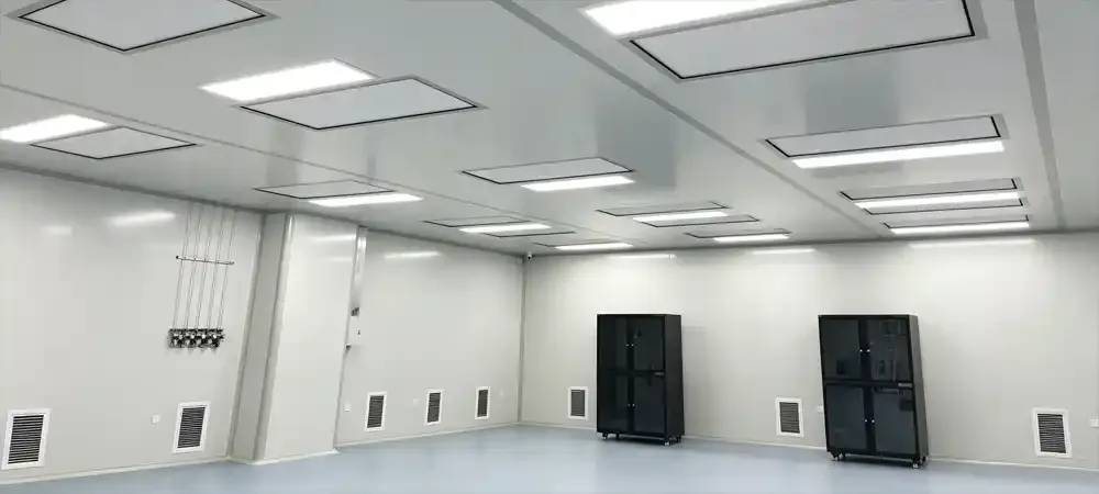
Project profile: 360 m² biopharmaceutical aseptic filling facility — Suzhou, China. ISO 5 core zone, ISO 7–8 surrounding areas. Construction: secondary steel conversion layer + aluminum T‑bar ceiling grid + steel blind panels + 680 Deiiang™ FFUs.
Challenges: High‑density FFU load with strict deflection limits; numerous non‑standard boundary panels with elevated leakage risk; GMP Annex 1 audit requirements for continuous sealing and stable pressure differentials.
Deiiang™ solution: Floor pre‑assembly + full‑section lifting of T‑bar modules; 3–5 mm pre‑camber to offset post‑installation settlement; double‑seal strategy — continuous gasket + neutral silicone at all interface positions; BMS‑linked zonal airflow auto‑balancing.
Quantified results (sample data): Ceiling leakage: 0.6 % @ +15 Pa; FFU velocity uniformity: ±8 %; noise: ≤52 dB(A); zero cleanliness classification degradation within 3 months post‑handover.
Product designer: Jason Peng, Deiiang™ Engineering
Localized Compliance: US / EU / CN Regulatory Alignment
Every cleanroom ceiling system must align with the local Authority Having Jurisdiction (AHJ). Below is a high‑level compliance map.
| Region | Key Standards | Terminology / Units | Documentation |
|---|---|---|---|
| US | NFPA 101/90A, UL 723, IBC; FM 4880/4882 | Imperial + metric; Class A flame spread index ≤25 | UL listing number, FM approval certificate |
| EU | EN 13501 (A2‑s1,d0), ISO 14644, EU GMP Annex 1 | CE marking; DoP file; noise per EU standards | CE Declaration of Performance, notified body report |
| CN | GB 50016, GB 50222, GB 50591, GMP (2020) | GB 8624 A2‑s1,d0; Chinese‑language test reports | Type test report, factory test report, incoming inspection report |
| Region | Core Standard | Key Requirement |
|---|---|---|
| US | NFPA 101 / UL 723 | Class A, FM listed |
| EU | EN 13501 | A2‑s1,d0, CE DoP |
| CN | GB 50016 / GB 8624 | A2‑s1,d0, type‑inspection report |
hreflang implementation: /en-us, /en-gb or /de-de, /zh-cn. Localize metadata, units, and case study contacts for each regional subdomain.
On‑Page Resources & Technical Downloads
Access the following internal resources for deeper technical guidance on your cleanroom ceiling system design.
ISO 14644 Basics — Understanding cleanroom classification
FFU Selection Guide — Sizing for ISO 5 through ISO 8
Cleanroom Sealants — Low‑VOC, high‑elasticity options
Case Studies — Deiiang™ project library
Downloads — Spec sheets, BIM families, test reports, installation manuals
External authoritative references: NFPA, UL, ISO 14644, GB Standards.
Frequently Asked Questions
What fire rating should a cleanroom ceiling have?
Target EN 13501 A2‑s1,d0 (EU) or UL 723 Class A (US). The entire assembly — structure, panels, sealants — must meet the rating as a system. For CN projects, aim for GB 8624 A2‑s1,d0.
Which sealants are ISO‑class compatible?
Use neutral‑cure silicone or modified silane with VOC <30 g/L. The sealant must be non‑corrosive to aluminum (avoid acetic‑cure types) and retain >90 % elasticity after aging. Always verify cleanroom compatibility via small‑scale off‑gassing tests before full application.
How to size FFUs for ISO 5?
Design for 0.45 ± 0.05 m/s face velocity (90–110 FPM). Calculate total air volume (m³/h) = ceiling area (m²) × velocity (m/s) × 3600. For a 100 m² ISO 5 zone at 0.45 m/s, you need approximately 162 000 m³/h total — refer to the Deiiang™ FFU Selection Table above to choose the right model combination (e.g., 81 units of the 2000 m³/h model, or a mix of smaller units).
How to test ceiling leakage post‑installation?
Per ISO 14644‑3, pressurize the plenum to +15 Pa above the cleanroom and measure leakage via calibrated flow meters. Acceptance criterion: ≤1 % of total supply air volume. For GMP Annex 1 environments, also perform PAO/MPPS challenge testing at every FFU filter interface.
Micro‑Glossary
| Term | Definition |
|---|---|
| A2‑s1,d0 | EN 13501 fire classification: A2 = essentially non‑combustible; s1 = very low smoke production; d0 = zero flaming droplets/particles. |
| UL 723 (ASTM E84) | Surface burning characteristics test; Class A = flame spread index ≤25, smoke developed index ≤450. |
| FFU | fan filter unit — a self‑contained ceiling module combining a fan with HEPA/ULPA filtration to deliver laminar airflow and maintain pressure differentials. |
| ISO 14644‑1 | International standard classifying cleanrooms by airborne particulate concentration per cubic meter. |
| Ceiling Leakage Rate | The percentage of supply air that escapes through the ceiling system at a specified pressure differential; target ≤1 % @ +15 Pa. |
| Secondary Steel Conversion Layer | A structural steel grid suspended from the building slab that carries all ceiling loads — T‑bar, blind panels, FFUs — without direct loading on the architectural ceiling. |
| Term | Definition |
|---|---|
| A2‑s1,d0 | Non‑combustible, low smoke, no droplets |
| UL 723 Class A | Flame spread ≤25, smoke ≤450 |
| FFU | Fan + HEPA/ULPA filter unit |
| ISO 14644‑1 | Cleanroom particle classification |
| Ceiling Leakage | ≤1 % @ +15 Pa target |
| Conversion Layer | Structural steel grid carrying ceiling loads |
References
NFPA 101 — Life Safety Code: nfpa.org/101
UL 723 / ASTM E84 — Surface Burning Characteristics: ul.com
EN 13501‑1 — Fire Classification of Construction Products: cen.eu
ISO 14644‑1 — cleanroom classification: iso.org
ISO 14644‑3 — Test Methods: iso.org
GB 50016 — (Building Fire Protection): gbstandards.org
GB 50591 — (Cleanroom Construction & Acceptance): gbstandards.org
EU GMP Annex 1 — Manufacture of Sterile Medicinal Products: ec.europa.eu
FM 4880/4882 — Cavity Fire Growth: fmglobal.com