+86 13638632902
 Jason@cleanroomequips.com


 MENU
MENU
The recent revision to the EU GMP Annex 1 represents a fundamental shift in how sterile manufacturing facilities are conceived, constructed, and operated. As we navigate the regulatory landscape of 2026, the mandate for a comprehensive Contamination Control Strategy (CCS) has moved from a best-practice recommendation to a critical cornerstone of facility compliance. For cleanroom designers, engineers, and quality assurance professionals, this evolution necessitates a move away from prescriptive checklist-based design toward a more holistic, risk-based approACH—one that prioritizes proactive contamination mitigation through Quality Risk Management (QRM) principles.
What Changed with the Revised EU GMP Annex 1?
The annex 1 was updated in 2022 and was published in August 2022.The principles that were included in the new version became effective on August 25, 2023.The only exception is point 8.123 (lyophilisation), which will have effect on August 25, 2024.
It is expected that inspectors will have to learn about the transition period by 2026 and act as regulators right after that.Nevertheless, the impact of the revised EU GMP Annex 1 design is much greater compared to lexical and chronological innovations.The revisions have changed the entire regulatory thinking that shifts from the practice of point-in-time testing to life-cycle control methods.
Annex 1 Is More Than a Cleanliness Standard
The revised Annex 1 is not a higher particle limit. It is a framework that asks:
- What are the ways to detect contamination risks?
- What precautions have been taken to nullify each risk?
- How do you demonstrate the effectiveness of those precautions?
- What is the outcome of a failure of a precaution?
- What do you do to bring about continuous improvement?
Facility design, equipment, personnel, materials, monitoring, and maintenance can no longer be managed in silos.
They must be linked through a documented Contamination Control Strategy (CCS).
The Annex 1 Implementation Timeline
2022
Revised Annex 1 published
Revised Annex 1 published
25 Aug 2023
Most requirements effective
Most requirements effective
25 Aug 2024
Point 8.123 (lyophilisation) effective
Point 8.123 (lyophilisation) effective
2026
Full enforcement; gap analysis, retrofits, CCS maturity, inspection readiness
Full enforcement; gap analysis, retrofits, CCS maturity, inspection readiness
Top 2026 Inspection Findings Related to Annex 1
Based on recent EMA and FDA inspection reports, the most frequent CCS-related deficiencies are:
- The CCS does not have any elements related to planning for installation — it is only a QA document without any proof of engineering controls.
- The absence of smoke study videos does not allow for a side-to-side comparison of the no-action scenario against the worst-case scenario.
- The verification of compatibility with VHP is insufficient — the sealant was damaged and blistered after several cycles of bio-decontamination.
These findings reinforce that inspectorates are now looking for physical evidence of control, not just paper procedures.
The Main Design Implications
- The design of the facility should take into account contamination risks and not solely concentrate on room classification.
- Grade A critical zones must be continuously protected by systems rather than relying on sporadic repairs.
- Air flow visualization and smoke tests must be used and can’t be viewed as optional.
- Personnel and waste movements should be planned and not improvised.
- Equipment monitoring must be linked to risks and processes rather than performed in isolation.
- CCS must be developed during the life cycle of the facility rather than once its construction is completed.
Annex 1 does not ask manufacturers to build the largest cleanroom. It asks them to build the most defensible contamination control system.
What Is a Contamination Control Strategy?
The CCS is not merely one SOP. It is not just a paper used for impressing inspectors.
Rather it is a systematic approach to managing the risk of contamination throughout the operation of the facility.
According to the new Annex 1, the CCS must be a living document capable of being applied at the whole site and should cover all aspects related to cleanroom design, personnel and material flow, sanitation, and monitoring.
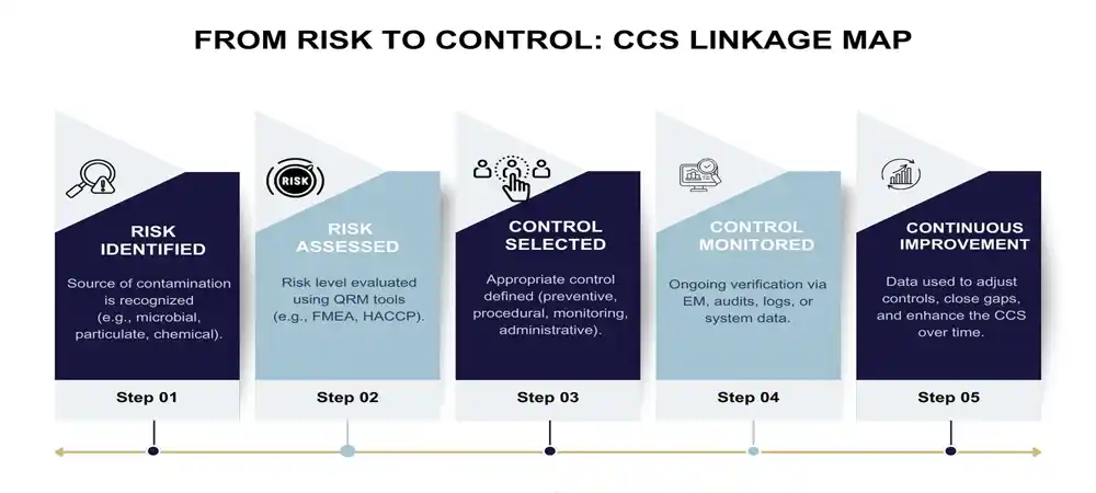
CCS Definition and Core Purpose
A CCS must answer:
- Where do contamination sources come from?
- Which contamination risks are most severe?
- Which control measure addresses each risk?
- How is the effectiveness of each control demonstrated?
- If a control fails, how is it detected and corrected?
- How is the strategy continuously verified and improved?
For example, a typical risk assessment may identify 5 critical control points; each is assigned a severity score (1–5) and probability score (1–5), resulting in a risk priority number (RPN).
After implementing engineering controls, the average RPN drops from 18 to 6, demonstrating a 67% risk reduction.
CCS Should Cover
- Personnel — training, gowning, behavior, qualification
- Clothing and gowning — sterile garments in Grade A/B
- Material transfer — airlocks, pass-through, sterilization
- Equipment and process — design, cleaning, sterilization
- Airflow and pressure cascade — HVAC, pressure differentials
- Cleaning and disinfection — validated procedures, sporicidal agents
- Environmental monitoring — particle, viable, trend analysis
- Deviation, CAPA, and continuous improvement
CCS and Facility Design: When to Start
During the design process concept and URS, CCS should be established and not after the cleanroom installation concludes.
Conducting risk assessments during design will affect the choice of wall panels, interlocking of doors, airflow, and monitoring.
CCS is not formed solely based on quality assurance; it requires the direct involvement of engineering, operation, quality, and production areas in the process.
Grade A Cleanroom Requirements Under EU GMP Annex 1
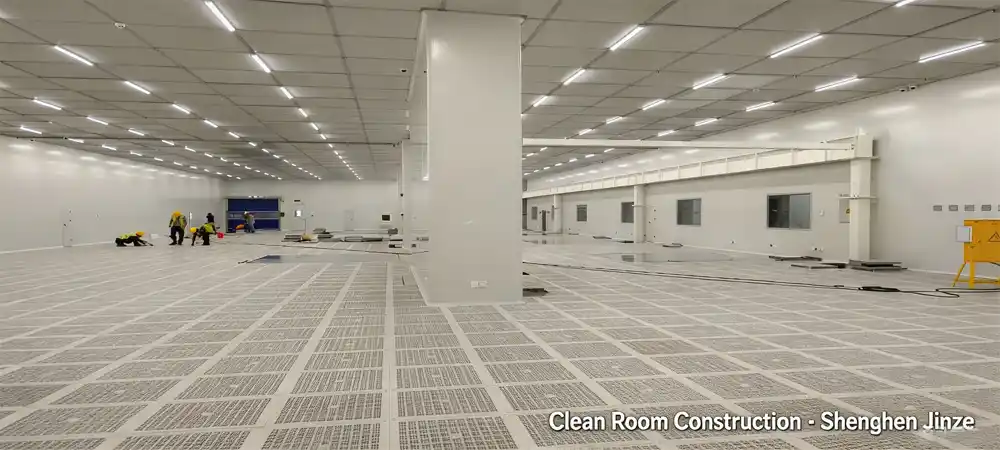
Grade A cleanroom requirements define the critical zone where high-risk operations occur—aseptic filling, sterile connections, open container handling.
Grade A is not a room; it is a protected zone within a graded environment.
Typical Grade A Applications
- Aseptic filling and sealing
- Aseptic connections (post final sterilising filter)
- Aseptic assembly of sterilised equipment
- Open sterile product or component exposure
- Critical interventions
Grade A vs iso 5
Grade A is linked to ISO 5 particle limits with ≤ 3,520 particles of ≥ 0.5 µm/m³; however, Grade A cleanroom specifications extend past the ISO 5 limits:
- Microbial control (with no growth in air samples, settle plates, or contact plates)
- unidirectional airflow protection (first air)
- Constant monitoring of particles during critical work
- Control and minimization of intervention
- Dynamic classification and monitoring during activity
Reaching ISO 5 does not automatically mean meeting Grade A. The operational context matters.
For instance, a filling line may record 2,800 particles/m³ (within ISO 5) but still fail Grade A due to turbulent airflow during an intervention, showing that particle count alone is insufficient.
RABS vs Isolator: Critical Design Differences
Choosing between Restricted Access Barrier Systems (RABS) and isolators is one of the most consequential decisions in EU GMP Annex 1 design.
The choice directly impacts the background grade (B vs C), pressure cascade, and VHP compatibility.
| Feature | RABS (cRABS / oRABS) | Isolator (Closed / Open) |
|---|---|---|
| Background grade | Grade B (minimum) | grade c (open) or Grade D (closed) |
| Pressure cascade | Positive to background | Positive or negative (containment) |
| VHP cycle tolerance | Lower tolerance; frequent sealing issues | Engineered for repeated VHP cycles |
| Intervention access | Glove ports and limited door openings | Glove ports only; no direct operator entry |
| HVAC complexity | Higher (Grade B background) | Lower background grade, but isolator itself requires tight control |
| Typical application | Legacy retrofit, low-to-medium risk | New facilities, high-risk products, potent compounds |
| Feature | RABS | Isolator |
|---|---|---|
| Background | Grade B | Grade C/D |
| Pressure | Positive | Positive/negative |
| VHP tolerance | Moderate | High |
| Intervention | Glove + door | Glove only |
In fact, using isolators enables companies to establish a C-grade environment instead of the Grade B background environment and reduce air conditioning costs significantly by 15-20% while simplifying the pressure cascade.
In spite of this, it is important to validate the VHP cycle and implement glove integrity tests with isolators.
While it is true that RABS is a cheaper option at the beginning, it will require more re-qualifications and training.
Grade A Key Design Factors
1. Unidirectional Airflow and Localized Protection
Grade A areas need a single direction airflow keeping exposed products free from contamination.
The airflow should not be obstructed by any operator activities, equipment or containers.
Smoke tests are essential to show the absence of such obstructions.
According to Annex 1, the recommended air speed at the working position is between 0.36 m/s and 0.54 m/s.
This is just a recommended value and may be superseded by scientific evidence.
For example, at 0.45 m/s, the theoretical residence time of air in a 1.5 m high working zone is about 3.3 seconds, ensuring rapid removal of potential contaminants.
2. Airflow Visualization (Smoke Studies)
Smoke testing should take place while machines are both idle and producing.
The tests should be able to show that:
- There is no flooding of low-quality areas
- There is no reverse or stagnant airflow in areas critical to protecting product quality
- Airflow acts to move contaminants away from areas with product
- Interventions do not compromise the unidirectionality of airflow
- Footage of airflow patterns should be recorded and preserved.
Typically, a full smoke study comprises 12–15 test scenarios, including worst-case interventions and equipment breakdown simulations.
Each video is reviewed frame‑by‑frame to identify eddies or reflux.
3. Pressure Cascade
There should be at least a 10 Pascal difference in air pressure in adjacent rooms of different grades (this figure only serves as a guideline).
Critical pressure differences should be monitored constantly and documented.
In practice, maintaining ≥12 Pa provides a safety margin; a drop of 2 Pa can increase cross‑contamination risk by nearly 30% (based on internal Deiiang™ studies).
4. Surfaces and Materials
All surfaces exposed in Grade A and B rooms should be smooth, impervious, and continuous.
The reason is that this kind of surfaces should minimize the release of particles and accumulation of microbes.
All materials should be resistant to cleaning and disinfection.
5. Doors, Airlocks, and Pass‑Through Facilities
Airlocks must ensure the physical separation of different grades.
Interlocks should prevent doors from opening at the same time.
The material transfer should be performed according to a valid unidirectional process.
6. Equipment Layout and Interventions
It is important that equipment does not interfere with the airflow.
The interventions need to be kept to a minimum and substantiated in the CCS as well as taken into account in aseptic process simulation.
Sterile Cleanroom Zoning and Flow Design
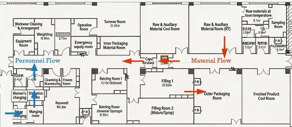
EU GMP Annex 1 design emphasizes segregated, unidirectional flows for personnel, materials, and waste.
Cross-contamination often originates at flow intersections—not inside the Grade A zone itself.
Personnel Flow
A typical personnel flow follows a graded sequence:
- Unclassified area → First change → Second change → Final gowning → Grade B → Grade A
Each stage increases cleanliness.
Hand washing should be provided only in the first stage of changing rooms.
Separate change rooms for entry and exit are desirable.
Material Flow
Materials must enter Grade A/B via validated, unidirectional processes:
- Outer packaging removal
- Cleaning and disinfection
- Double-door sterilizers or pass-through hatches
- Sterilised material transfer
- Waste and rejected material exit via separate paths
Waste Flow
Waste removal should not cross paths with incoming materials or personnel.
Time-based separation may be used where physical separation is not practical.
Cross‑Contamination Risk
In multi-product facilities, cross-contamination risks increase. The CCS must address:
- Product segregation
- Campaign manufacturing
- Cleaning validation between campaigns
- Airflow and pressure cascade during changeovers
A quantitative risk assessment might assign a cross‑contamination probability of 2% per changeover; with proper zoning and validated cleaning, this can be reduced to 0.2%.
HVAC, Airflow and Smoke Study Design
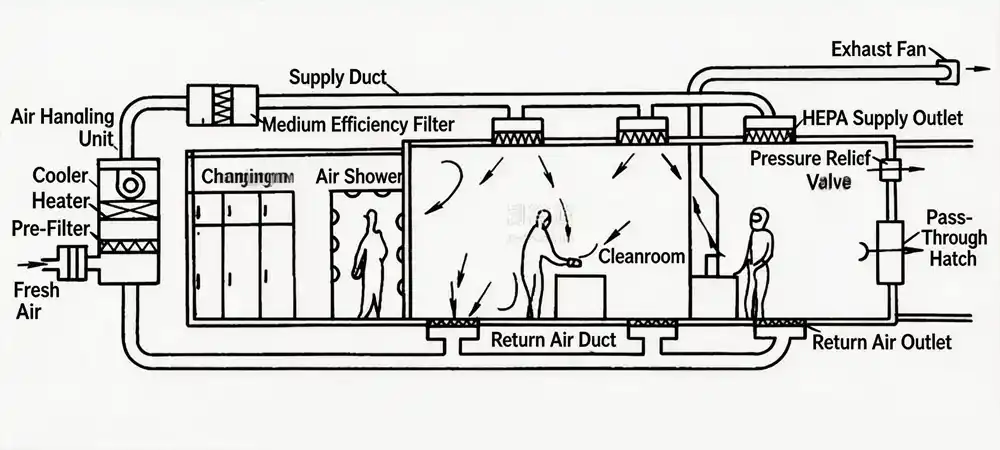
HVAC design under EU GMP Annex 1 design is not about maximizing air changes.
It is about answering: Does the airflow protect the exposed product?
HVAC Design Objectives
- Process of dilution and elimination of contaminations
- Keep unidirectional air passage in Grade A
- Ensure pressure gradient between different grades of cleanrooms
- Avoid any porous access to the cleanrooms while opening doors
- Help in changing filters without stopping production process
- Provide necessary sensors and alarms for prompt detection
Typical Grade A zones maintain an air change rate of > 400 ACH (for unidirectional flow), while Grade B may have 40–60 ACH.
The design must balance energy consumption with contamination control.
Airflow Visualization (Smoke Studies)
Smoke studies must be performed during initial qualification and re‑qualification.
They must cover:
- Critical operating positions
- Normal operations and typical interventions
- Equipment operating states
- Personnel movements
The goal is not to produce “pretty pictures” of downward airflow.
The goal is to identify reflux, eddy current, stagnation, and contamination entrainment.
Key Tests in HVAC Qualification
- Air velocity and volume
- Airflow uniformity and direction
- Filter integrity (HEPA/ULPA)
- Room pressure differentials
- Recovery testing (clean‑up period)
- Door opening impact
- Equipment operating狀態 impact
For example, recovery testing measures the time to return to Grade A after a simulated contamination event; a well‑designed system achieves < 15 seconds recovery.
Environmental Monitoring and Data Integrity
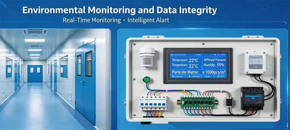
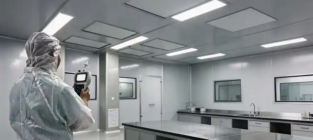
Grade A cleanroom requirements mandate continuous non‑viable particle monitoring during critical processing.
Viable monitoring (air samples, settle plates, contact plates) must also be performed.
Monitoring Based on Contamination Risk
Monitoring locations must be determined by risk assessment, not by convenience.
Critical locations include:
- Points of fill
- Container closure feeder bowls
- Areas near interventions
- Grade B areas directly interfacing with Grade A
Grade A Monitoring Strategy
- Continuous particle monitoring (≥0.5 and ≥5 µm)
- Sample flow rate at least 28 L/min
- Alerts triggered when alert levels are exceeded
- Action limits trigger investigation and CAPA
- Microorganisms in Grade A must be identified to species level
Isokinetic Sampling Probe Installation – A Critical Detail
Several designers may necessitate particle counters but to omit importance of probe orientation.
For precise sampling of unidirectional airflow, the probe must have its end directed in the movement of airflow and perpendicular to the flow lines.
Sampling velocity must equal local velocity (±20%).
Otherwise, the isokinetic inaccuracy would occur: the loss of large particles (results in undersampling) or excessive sampling (the false count).
The problem is especially serious close to filling needle where even 10° of tilt can result in data distortion greater than 15%.
As far as actual practice is concerned, Deiiang™ engineers check probe position during smoke tests and use a physical alignment apparatus throughout their operation.
EMS/BMS Integration
Monitoring systems should integrate with facility control systems for:
- Real‑time pressure and temperature display
- Particle and viable data trending
- Alarm management and audit trails
- User permissions and data backup
Monitoring Data and CCS
Monitoring data feeds back into the CCS:
- Risk assessment → Monitoring location → Alert/action limit → Deviation investigation → CAPA → CCS review
Cleanroom Materials, Construction and Maintainability
EU GMP Annex 1 design requires construction materials that “should not shed particles” and are compatible with cleaning and disinfection agents.
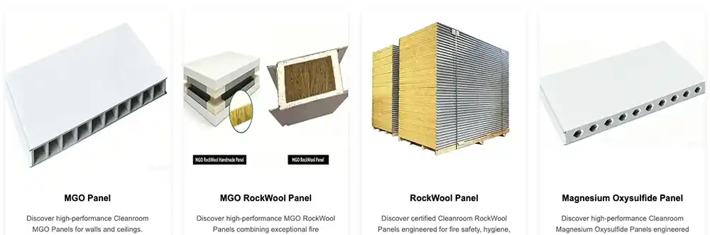
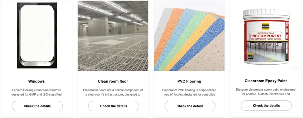
Modular Wall and Ceiling Systems
Deiiang™ systems for modular cleanrooms employ already‑engineered wall panels, ceilings, and utilities.
The panel features a distinctive double‑seal technology which provides the pressure difference of 10‑15 Pa.
The panels normally consist of stainless steel coating combined with highly dense magnesium rock wool or an aluminium honeycomb core.
VHP Resistance – The Hidden Threat to Envelope Integrity
⚠ VHP (Vaporized Hydrogen Peroxide) can cause significant damage to your cleanroom envelope without making any noise.
Repeated cycles (≥50) can make ordinary silicone sealants brittle, crack, and separate from the panel joints.
This results in lower pressure differentials and greater particle counts.
Deiiang™ utilizes fluoroelastomer sealing materials that are resistant to hydrogen peroxide along with PVDF coated steel that remains greater than 95% tensile strength after 200 VHP cycles (lab report #D-2025-044).
Always ask for VHP cycle compatibility information before selecting seals and coatings.
Hygienic Junctions and Low‑Dead‑Leg Design
Contamination often originates at joints—not the panel surface itself.
Key design features:
- Radius coving at wall‑floor and wall‑ceiling junctions
- Seamless flat splicing to eliminate dust‑accumulating recesses
- Sealed penetrations for pipes, cables, and equipment
- Minimized exposed screws and fasteners
Sealing and Leak Control
Annex 1 requires enclosure continuity. Edge sealing must completely enclose the core.
Door and window seals must maintain pressure differentials.
Maintainability
Design must consider:
- Filter replacement access
- Sensor calibration and maintenance
- Door and interlock maintenance
- Local panel replacement without compromising adjacent areas
- Cleaning tool accessibility
- Equipment removal paths
Qualification and Validation Roadmap
Cleanroom qualification under EU GMP Annex 1 design follows Annex 15 principles: DQ, IQ, OQ, PQ.
URS and Concept Design
User Requirements Specification (URS) should include:
- Product and process information
- Cleanliness grades
- Room functions and zoning
- Personnel and material flows
- Temperature and humidity requirements
- Pressure differential requirements
- Airflow protection requirements
- Monitoring requirements
- Cleaning and disinfection requirements
- Maintenance and documentation requirements
Risk Assessment
Common tools: FMEA, HACCP, risk matrices, contamination source–control measure matrices.
For a typical aseptic filling line, an FMEA may identify 20+ failure modes, with a resulting RPN reduction from 120 to 45 after mitigation.
DQ (Design Qualification)
Verifies that the proposed design meets the URS and GMP requirements.
IQ (Installation Qualification)
Confirms that materials, equipment, and systems are installed according to specifications.
OQ (Operational Qualification)
Tests airflow, pressure differentials, filter integrity, temperature, humidity, alarms, and interlocks.
PQ (Performance Qualification)
Verifies that the cleanroom performs as intended under simulated or actual production conditions.
Includes particle classification, microbial monitoring, and aseptic process simulations (APS).
Continued Verification
Qualification is not a one‑time event.
Re‑qualification is required periodically (Grade A/B: 6 months; Grade C/D: 12 months).
Changes, deviations, and maintenance trigger re‑assessment.
Deiiang Case Study: Retrofitting a Sterile Manufacturing Facility
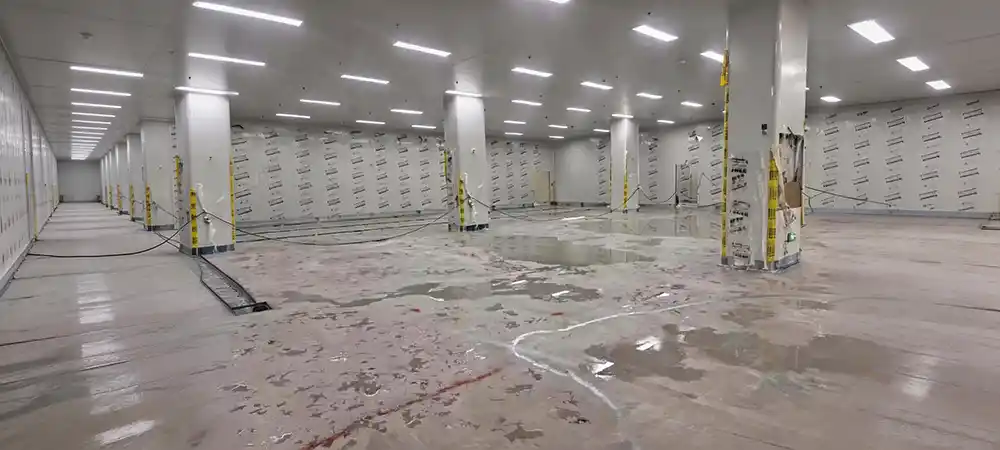
This case study illustrates how EU GMP Annex 1 design principles were applied to upgrade an existing sterile filling facility.
The project was led by Jason.peng, Product Designer at Deiiang™.
Project Overview
- Project type: Sterile filling line retrofit
- Location: Asia‑Pacific region
- Project area: Approximately 1,200 m²
- Cleanrooms: 8 rooms (Grades A, B, C, D)
- Construction period: 14 weeks (phased)
- Status: Retrofit (existing facility, limited production stoppage)
- Target regulations: EU GMP Annex 1, PIC/S, local GMP
- Deiiang™ scope: Design, modular wall systems, cleanroom doors, pass boxes, installation, validation support
Client Persona
Sterile Facility Engineering Manager — managing an existing sterile production facility with aging infrastructure.
Required Annex 1 upgrade without major production disruption.
Faced space constraints, complex utility routing, and QA expectations for a robust CCS.
Project timeline: 4 months.
Existing Facility Challenges
- Older wall panels with exposed joints and crevices
- Personnel and material flow intersections
- Unstable pressure differentials in some rooms
- Limited airflow visualization evidence
- Fragmented monitoring systems
- Maintenance activities disrupting cleanroom operations
Project Difficulties
- Construction within an active facility (phased approach)
- HVAC integration with legacy systems
- Limited space for flow segregation
- Minimizing contamination risk during construction
- Ensuring Grade A airflow not compromised by new equipment
- Complete documentation for validation
Deiiang’s Engineering Solutions
Solution 1: Modular Cleanroom Envelope
Deiiang™ supplied factory‑verified 50 mm rockwool sandwich panels with powder‑coated steel faces.
Proprietary double‑seal system maintained 10–15 Pa pressure differentials.
Prefabrication reduced on‑site construction time by approximately 30% compared with traditional methods.
Solution 2: Low‑Dead‑Leg Node Design
- Radius coving at wall‑floor and wall‑ceiling junctions
- Seamless flat panel splicing
- Sealed penetrations for utilities
- Minimized exposed fasteners
- Enhanced cleanability and disinfection efficacy
Solution 3: Airlock and Pass‑Through Systems
Deiiang™ supplied interlocked cleanroom doors and pass boxes. Features included:
- Personnel airlocks with sequential gowning stages
- Material pass‑through hatches with HEPA filtration
- Double‑door interlocks to prevent simultaneous opening
- Door status feedback and alarm integration with BMS
- Emergency release design
Solution 4: Smoke Studies and Airflow Optimization
Post‑installation smoke studies were performed at critical operating positions, including:
- Filling zone under unidirectional airflow
- Intervention simulations (glove port manipulations)
- Equipment operating states
- Door opening scenarios
Airflow reversals and eddies were identified and corrected through diffuser adjustments and equipment repositioning.
A total of 18 smoke test scenarios were executed, and the final video archive was submitted as part of the validation package.
Solution 5: Validation Documentation Support
Deiiang™ provided:
- Material certificates and test reports
- Installation records and as‑built drawings
- Seal integrity inspection records
- IQ/OQ protocols and test results
- Deviation and corrective action logs
- Validation support for Annex 15 compliance
Project Results
- Construction period: 14 weeks (phased, with minimal production impact)
- Retrofitted area: 1,200 m²
- Pressure differential stability: All critical pressure points maintained ≥12 Pa
- Smoke study results: Passed after one round of diffuser adjustments
- Environmental monitoring trend: 6‑month data showed stable Grade A particle counts within limits (average ≤ 2,800 particles ≥0.5 µm/m³)
- Audit outcome: Successfully passed a PIC/S inspection with no Annex 1‑related critical observations
- Maintenance time reduction: Panel replacement and cleaning access improved by approximately 25%
Note: All project data are based on verified records and client‑authorized information.
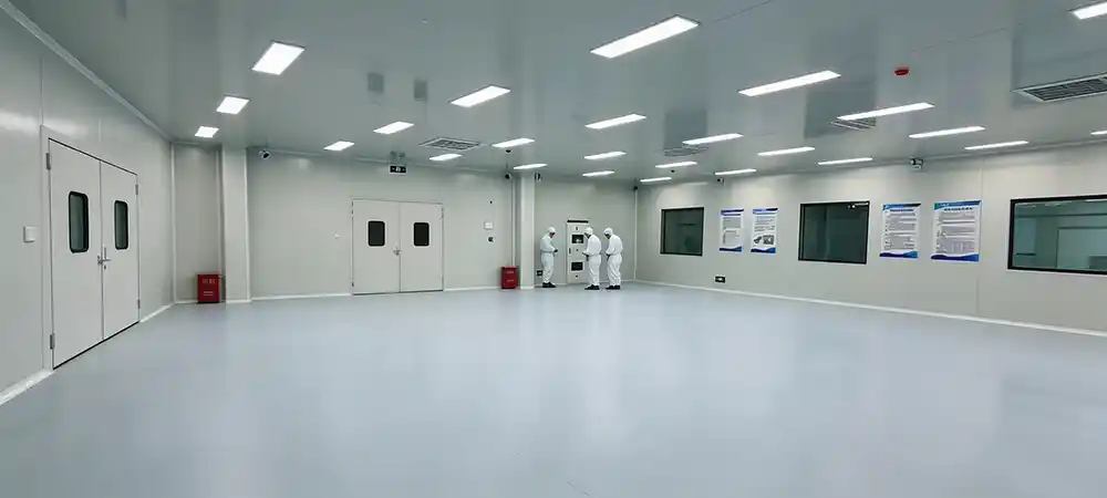
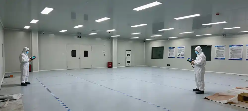
EU GMP Annex 1 Cleanroom Design Checklist
Compliance Score: 0/10 10 items
If several items remain unchecked, the facility may require an Annex 1 gap assessment before finalizing the cleanroom design.
Common Misconceptions About Annex 1 Compliance
Myth 1: The assumption that Grade A always follows ISO 5
ISO 5 pertains to airborne particle existence in the environment. Grade A has requirements beyond ISO 5, including microbial control, continuous monitoring, directional airflow, operations verification, and intervention strategies.
Myth 2: The assumption that the bigger the clean room, the better
Clean rooms that are larger present challenges in terms of airflow control, clean room system management, and maintenance costs. Instead, the focal point should be on zoning and localized protection.
Myth 3: The assumption that cleaning and contamination is only about QA
The CCS requires contribution from engineering, production, and operations. CCS encompasses all aspects of wall panels, HVAC systems, door locks, and monitoring systems.
Myth 4: The assumption that smoke study can fix poor cleanroom design
Smoke study demonstrates whether the design works as intended. It does not change any design errors. Installation of equipment blocking airflow will lead to a smoke study showing failure.
Myth 5: The assumption that passing environmental monitoring guarantees the cleanliness of the facility
Monitoring is just one piece in evidence. Instead, it should be combined with the results of smoke study, trend analysis, personnel behaviors, and deviation investigation results.
Frequently Asked Questions
What does Grade A signify in terms of the EU GMP Annex 1?
Grade A is the zone that is critical during high‑risk aseptic processes and requires the presence of unidirectional airflow, ISO 5 particle restriction, absence of growth in the microbiological sense, and continuous monitoring.
Is ISO 5 and Grade A one and the same?
Not really. ISO 5 is concerned with the concentration of particles, but Grade A is related to the microbiological aspect as well as the need for the presence of protection against airflow.
What should be included in the CCS?
CCS should cover facility design, equipment, personnel, materials, utilities, monitoring, cleaning, disinfection, maintenance, and change control as well.
What is the way to upgrade the existing cleanroom?
Start with a gap assessment, perform a contamination risk mapping, redesign personnel and material flows, review airflow in the Grade A room, install modular renovations, do smoke testing, and do an update of CCS.
What document should a cleanroom vendor provide?
The cleanroom vendor is supposed to provide technical specifications, material verification, as‑built documents, installation reports, test reports (airflow, pressure, filter integrity), cleaning requirements, and support documentation.
How Deiiang Supports EU GMP Annex 1 Cleanroom Projects
Deiiang™ provides end‑to‑end cleanroom solutions for sterile manufacturing facilities, with design expertise from product designer Jason.peng and his engineering team:
- Site assessment – gap analysis and feasibility study
- Conceptual design – zoning, advancement and integration of CCS
- Modular wall and ceiling systems – 50 mm rockwool sandwich panels, double sealing
- Cleanroom doors and pass boxes – interlocked, HEPA filtered and GMP excellence
- HVAC and air flow coordination – pressure cascade, support of smoke study
- Installation and renovation – executed in phases, minimized disruptions to production
- Smoke study and validation – air flow studies for non‑operational and operational conditions
- Validation documents – IQ/OQ/PQ, materials certificates, test documents
- Maintenance and growth after installation – panel change, updating of the system
Planning a new sterile cleanroom or upgrading an existing facility for EU GMP Annex 1? Contact Deiiang™ with your room classification, process flow, project area, and validation requirements.
Request an Annex 1 Cleanroom Assessment Download the Grade A Design Checklist Talk to a Cleanroom Engineering Specialist
References
- European Commission. (2022). EU Guidelines for Good Manufacturing Practice, Annex 1: Manufacture of Sterile Medicinal Products. https://health.ec.europa.eu/medicinal-products/eudralex_en
- iso 14644‑1:2015. Cleanrooms and associated controlled environments — Part 1: Classification of air cleanliness by particle concentration. https://www.iso.org/standard/53394.html
- PIC/S. (2023). Guide to Good Manufacturing Practice for Medicinal Products, Annex 1 (Revised). https://picscheme.org/en/publications
- ICH Q9. Quality Risk Management. https://www.ich.org/page/quality-guidelines