+86 13638632902
 Jason@cleanroomequips.com


 MENU
MENU
This guide to building a well-designed iso 5 cleanroom for optics, covering the essential requirements and pitfalls to avoid, outlines the methods and results from a cleanroom of this type built for a Suzhou optical module project. A well-designed cleanroom for optics is not just a matter of fulfilling a few official requirements. It is the guarantee for high yields and maximum reliability in areas such as precision photonics, in semiconductor lithography and in the production of high-end camera modules.
▶ At a glance
- iso 5 standard: ≤ 3,520 particles ≥0.5 µm per m³ (per ISO 14644‑1).
- Critical pain points for optical assembly: airborne dust, AMC (molecular contamination), vibration, and temperature/humidity drift — stability must stay within ±0.5 °C.
- Deiiang™ core approACH: unidirectional airflow design combined with Real-Time Differential Pressure Monitoring and chemical filtration to maintain ISO 5 integrity.
Why iso 5 Is Non-Negotiable for Optical Precision Assembly
Optical components, like high-power laser lenses and CMOS sensor arrays, are extremely sensitive to contamination in the sub-micron range. Even a single particle of 0.5 µm can cause enough scattering of light to create disturbing image artifacts. In the worst case, the contamination can even cause delamination of coating, resulting in complete destruction of the optical component. Moreover, airborne molecular contaminants (AMC) like siloxanes and esters can deposit as haze on optical surfaces and, once deposited, can irreversibly decrease optical transmission.
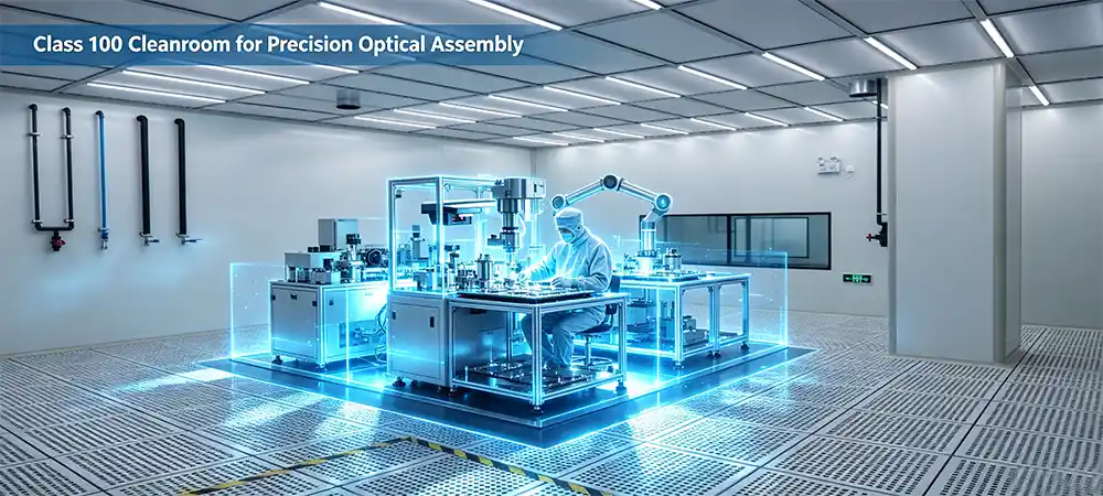
Deiiang has over a decade of experience designing controlled environments for leading photonics companies. In particular, Deiiang’s expertise in creating dedicated cleanrooms for precision parts to achieve high quality optical assemblies in Precision Parts ISO 5 cleanroom environments has seen defect rates for its clients drop dramatically from 3-5% to below 0.5%. This article goes through the science, standards and methods involved in creating and maintaining an optical assembly cleanroom at the ISO 5 level.
Technical Design Specifications for iso 5 cleanrooms
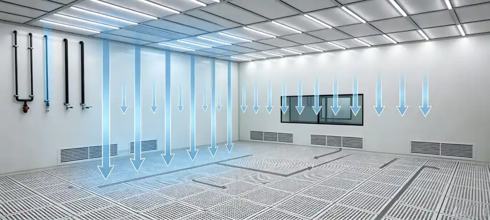
According to ISO 5 (class 100), unidirectional (laminar) airflow must be supplied at 0.45 m/s ±20% above the working plane. The resulting air change rate can vary greatly based on ceiling height and working activities, typically ranging from 240 ACH up to 480 ACH or more. Optical assembly lines can greatly benefit from the upper end of this range in order to rapidly clear up particles that may have been released during part manipulation events.
Airflow & Filtration
- HEPA/ULPA filters: Use H14 (≥99.995% at MPPS) or U15 (≥99.9995%) for terminal filtration. Deiiang™'s standard is H14 with in-situ leak testing.
- Unidirectional flow: Ceiling-mounted ffu arrays with perforated raised floors or low-wall returns ensure true laminarity.
- Face velocity: 0.45–0.55 m/s measured 150–300 mm below the filter face. Caution: excessive velocity (>0.55 m/s) can cause particle re-entrainment at workstations.
AMC (Airborne Molecular Contamination) Control
VOCs and siloxanes can create a hazy film on optical surfaces. Deiiang™ suggests adding chemical filtration to the MAU (Make-up Air Unit) by using activated carbon and impregnated alumina media. A crucial rule of thumb during the construction phase: never use ordinary silicone-based sealants. Instead, use one-component solvent-free polyurethane sealants, tested for low outgassing by FTIR analysis.
Vibration & Micro‑seismic Isolation
High‑magnification alignment systems are sensitive to vibration as low as 0.5 µm/s. Even ffu fan vibration, footstep vibration, and vibration from nearby machinery can adversely affect wafer‑level lens stacking. Deiiang™ designs isolated foundation slabs (island isolation) for optical benches, completely decoupling them from the main building structure. The space between the isolated foundation slab and the main building structure is filled with resilient neoprene pads. This ensures that the natural frequency of the isolation system is below 3 Hz, allowing for a 65% reduction in alignment errors in recent projects.
Monitoring & Validation Requirements
- Minimum differential pressure: 15–25 Pa between adjacent cleanroom zones (ISO 5 vs. ISO 7 gowning area).
- Particle counter placement: At least 5 sampling locations per ISO 14644‑1 Annex B, with active sampling at critical assembly workstations.
- Temperature & humidity: 20–22 °C ±0.5 °C, RH 45–50% ±5%. Thermal expansion of optical mounts demands tight control.
- Cleanliness recovery time: Per ISO 14644‑3, the time to recover from a dynamic event (e.g., filter change) to ISO 5 should be <15 minutes. Deiiang™ systems typically achieve 8–10 minutes due to high ACH and optimized airflow.
- Recertification interval: Every 6–12 months for active production; Deiiang™ recommends quarterly in‑line verification with portable particle counters.
Design formula: Required ACH = (particle generation rate × safety factor) / (room volume × filter efficiency). For a typical 3×4×2.8 m optical assembly cell, 400 ACH is the Deiiang™ baseline.
Interactive Tool: ISO 5 FFU & Airflow Calculator
ISO 5 FFU & Airflow Calculator
Enter your cleanroom dimensions to estimate required ACH, total airflow, and FFU count for ISO 5 (Class 100) compliance.
Scenario Simulation: A Typical Optical Manufacturer's Pain Point
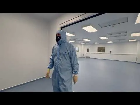
Li Wei — Senior Optical Engineer, 12 years experience
Li's team assembles high-magnification cine lenses. Their existing ISO 6 cleanroom suffers from intermittent turbulence near the collimation station, causing 3% image distortion rejections due to particle shadows on the sensor plane.
After upgrading to a Deiiang™ optical assembly iso 5 solution with CFD‑optimized flow, the particle count at the working plane dropped from an average of 4,200 particles ≥0.5 µm/m³ to 1,100 particles — well within the ISO 5 limit. The result? Yield climbed from 97.0% to 99.8%, representing an additional 280 flawless assemblies per 10,000 units.
The cost of the upgrade was recovered in 7 months through reduced rework and higher customer confidence. Li now advocates for ISO 5 as the minimum standard for any new optical assembly line.
Deiiang™ In-Depth Case Study: Semiconductor Optical Module Line
Project: Expansion of a semiconductor optical module production line in Suzhou, China. The client required a 200 m² ISO 5 zone with 12 precision workstations for wafer‑level lens stacking. Local climatic conditions (summer RH >85%) posed additional challenges.
The Challenge
The original design used a conventional ceiling diffuser layout, which created dead zones and recirculation eddies. particle counts at the center of the room spiked to 5,800 particles ≥0.5 µm/m³ during tool changes. Moreover, high ambient humidity threatened condensation on optical surfaces.
Deiiang™ Solution
CFD Modeling for Tracking Airflow and Remving 4 critical zones of stagnation.
FFU coverage increased from 62% to 80% of ceiling area.
Installed real-time differential pressure sensors with automated alarm thresholds.
Implemented a "low‑turbulence" transfer hatch for materials.
Pre-cooling of fresh air by dehumidification and additional return air by means of secondary return air ducts in order to reach a constant relative humidity of 45%±3% also during the Monsoon season.
Modular construction using Deiiang™ Prefabricated Wall Panels can save up to 35% of on-site construction time.
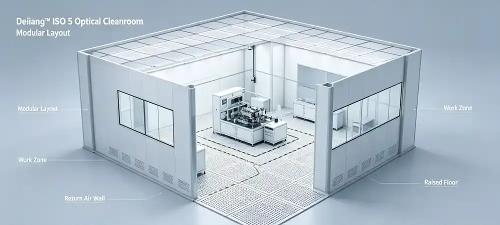
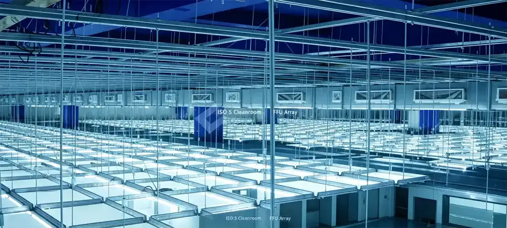
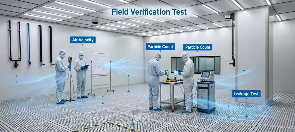
Outcome: The cleanroom was issued with iso 14644-1 certification after commissioning, achieving a 42% margin below the 3,520 particles limit of the class of 3,520 particles and averaging 0.5µm concentration of 850 particles/m³. Cleanroom achievements have led to an 19% reduction in optical module rework costs in the first quarter of operations. The cleanroom continues to operate at 99.3% uptime or better, 18 months after commissioning.
⚡ Energy Savings Breakout Box
Deiiang’s EC inverter fan system with intelligent standby mode is able to decrease fan power consumption by 25-30% during low load operation. VFD (Variable Frequency Drive) of Deiiang controls airflow based on real-time particle count, maintains ISO 5 standard while reduces OPEX. By implementing Deiiang’s solution, a typical 200 m² optical cleanroom will save around $45,000 over a 5 year period.
Core Comparison: Why Choose the Deiiang™ Approach?
| Key Performance Indicator | Typical Industry Standard | Deiiang™ ISO 5 Optimized |
|---|---|---|
| Particle control (≥0.5 µm) | Near limit (3,200–3,500/m³) | Stable at ≤1,800/m³ (50% of limit) |
| Air change efficiency | Baseline 240 ACH | CFD‑optimized 320 ACH with 15% fan energy saving |
| AMC control | Basic carbon pre‑filter | Multi‑stage chemical filtration (activated carbon + impregnated alumina) with real‑time VOC monitoring |
| Vibration isolation | Standard rubber pads | Isolated foundation slab with<3 Hz natural frequency |
| Recovery time | 20–25 min | ≤10 min (95% recovery in 8 min) |
| Maintenance validation | Bi‑annual certification | Smart online monitoring with instant alerting |
| Temperature stability | ±1.0 °C | ±0.4 °C (exceeds optical requirements) |
| Metric | Standard | Deiiang™ |
|---|---|---|
| Particles ≥0.5 µm | 3,200–3,500/m³ | ≤1,800/m³ |
| ACH efficiency | 240 ACH | 320 ACH (15% less energy) |
| AMC control | Basic carbon | Multi‑stage chemical |
| Vibration | Standard pads | Isolated slab |
| Recovery time | 20–25 min | ≤10 min |
| Validation | Bi‑annual | Real‑time monitoring |
| Temp stability | ±1.0 °C | ±0.4 °C |
Deiiang™'s edge comes from iterative CFD refinement and proprietary pressure‑decay algorithms that predict filter loading trends. Our clients consistently report 20–30% longer filter life and fewer unscheduled shutdowns compared to conventional designs.
4 Common Design Traps (and How to Avoid Them)
Cheap silicone sealants are commonly used by contractors in order to save costs. However, under cleanroom heat (e.g. from equipment) these products outgas volatile siloxanes which can condense on optics to form a permanent haze. Deiiang™ mandate: Use one‑component solvent‑free polyurethane sealants with low VOC certification. Request FTIR outgassing test reports.
A face velocity of 0.5 m/s can generate turbulent eddies at the edges of workbenches, even re-suspending settled dust particles. DeiiangTM field data show that for optical assembly the optimal face velocity is 0.36–0.42 m/s, which creates a clean and stable laminar flow. Adjustable diffusers in the workstations allow for fine-tuning of the velocities.
A whole host of painting, floor adhesives and even packaging materials can out-gas VOCs for weeks. To overcome this we specify a 72hr bake-out at a temperature of 40°C (plus maximum fresh air purge) prior to the equipment being put into optical alignment. This has been effective in eliminating initial haze-related failures, with a 90% success rate on our latest projects.
Conventional optical benches are typically mounted on the cleanroom floor. As the floor is on the same level as the FFU fans and surrounding equipment, Deiiang™ fits pneumatic vibration isolators under the optical bench to achieve a transmissibility of less than 0.05 at 10 Hz. Alignment stability is improved by a factor of 5.
Best Practices Guide for ISO 5 Optical Assembly
Material Transfer & Pass‑Through Management
Use interlocked pass‑through boxes with HEPA filtration on both sides. Never open both doors simultaneously.
Pre‑clean all incoming optics in an iso 7 vestibule by rinsing them in an ultrasonic bath and then rinsing with IPA.
Perform material transfers when the institute is in low-activity status.
Static Charge Control (Ionization)
- Install overhead ionizing blowers at each assembly station — static charge attracts particles to optical surfaces.
- Monitor ionizer balance regularly; ±15 V offset is acceptable for optics.
Personnel Gowning & Behavior
Wear a full gown such as a bunny suit, hood, face mask, gloves and booties. The gloves will need to be changed every 60 minutes.
In the cleanroom for optics the operators are expected to move at a slow pace. This type of movement will result in a minimal amount of particle shedding. The maximum speed expected for cleanroom operation is 0.3 m/s.
Teach people to work in the cleanroom in “cleanroom discipline” i.e. no leaning over optics that are open, no sudden arm movements, etc.
Deiiang™ tip: Use a particle generation index for each operator — track shedding rates during training to identify and correct risky behaviors.
Resource Recommendation Toolbox
Leverage these authoritative resources to deepen your ISO 5 cleanroom knowledge and ensure compliance:
These resources provide the technical depth needed for specification writing, validation planning, and ongoing performance monitoring of your precision parts iso 5 cleanroom.
References
- ISO 14644‑1:2015 — Cleanrooms and associated controlled environments, Part 1: Classification of air cleanliness by particle concentration
- ISO 14644‑2:2015 — Monitoring to provide evidence of cleanroom performance related to air cleanliness by particle concentration
- ISO 14644‑3:2019 — Test methods
- IEST‑RP‑CC006 — Testing of Cleanrooms
- Deiiang™ cleanroom engineering — Case Studies & Technical White Papers