+86 18186671616
 Jason@cleanroomequips.com
 MENU
MENU
Purpose of Air Parameter Control
The purpose of controlling the air parameters of the Dust-free workshop is to check whether the dust-free workshop meets the given cleanliness level. Whether it is the Dust-free workshop inspection stage after the commissioning work is completed, or the dust-free workshop use stage, the air parameters control work must be completed. The test and control methods of the dust-free workshop air parameters are formulated and proposed in detail in various standards and recommendations.
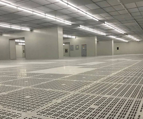
Parameters to Control in Dust-Free Workshops
Air Particle Concentration
Measurement of suspended particles at various size thresholds to determine cleanliness levels
Airflow Characteristics
Wind speed, unidirectionality, Air volume, and Ventilation frequency measurements
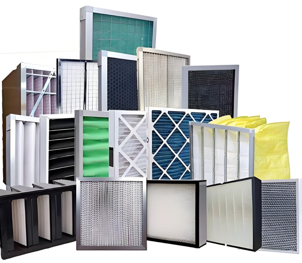
Filter Integrity
Testing HEPA and ULPA filters for leaks and proper installation
Environmental Conditions
Temperature, humidity, and pressure differential monitoring
ISO Cleanliness Classification Standards
Both dust-free workshops and clean areas are divided into levels according to one indicator: the maximum allowable concentration of particles of a certain particle size (the number of particles in every 1m³ of air).
| ISO Level | 0.1 μm | 0.2 μm | 0.3 μm | 0.5 μm | 1.0 μm | 5.0 μm |
|---|---|---|---|---|---|---|
| ISO 1 | 10 | 2 | - | - | - | - |
| ISO 2 | 100 | 24 | 10 | 4 | - | - |
| ISO 3 | 1,000 | 237 | 102 | 35 | - | - |
| ISO 4 | 10,000 | 2,370 | 1,020 | 352 | 83 | - |
| ISO 5 | 100,000 | 23,700 | 10,200 | 3,520 | 832 | 29 |
| ISO 6 | 1,000,000 | 237,000 | 102,000 | 35,200 | 8,320 | 293 |
| ISO 7 | - | - | - | 352,000 | 83,200 | 2,930 |
Note: The concentration value Cn should be rounded off to three decimal places. In actual situations, there is an actual error in particle concentration, and it is impossible to calculate a concentration with high accuracy.
Cleanliness Level Testing Procedure
When testing the cleanliness level of a dust-free room, the concentration of suspended particles at one or several points in the dust-free room should be measured:
Confirm Workshop State
Ensure the dust-free workshop is in the appropriate state (static or dynamic) for testing
Determine Sampling Points
Establish number and location of sampling points for given particle sizes
Set Sampling Parameters
Determine samples per point, sampling volume, and sampling time
Record & Analyze Data
Statistically record particles, enter data, and analyze results against standards
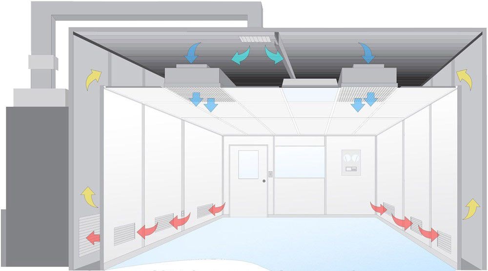
Airflow Testing Standards
Airflow in the dust-free workshop must be measured and evaluated for proper operation:
- Measurement Location: Wind speed in unidirectional airflow is measured 150-500 mm from the source
- Test Points: At least three evenly distributed test points required
- Measurement Duration: Each point should be measured for ≥10 seconds
- Uniformity Requirements: Wind speed difference should not exceed 20%-30%
cleanroom airflow pattern and testing locations
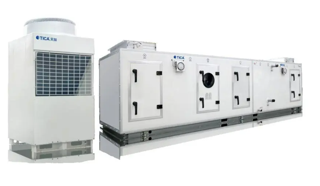
Environmental Control Parameters
General temperature control should be carried out during commissioning and at all stages of clean room testing and use. Controlled at workbench height and other working points.
Measurement: Periodic continuous testing for 6 minutes within 1 hour or more
Standard Range: 20-26°C
Relative humidity control is performed after the ventilation and Air conditioning system is stable. At least one point is set in each area where relative humidity is required.
Measurement: Duration not less than 6 minutes to stabilize sensors
Standard Range: 40-70% RH
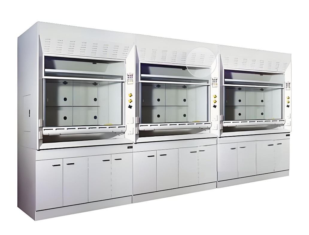
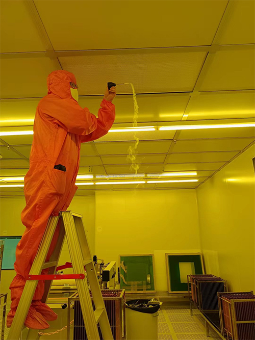
The final filter (HEPA, ULPA filter) is an important part of the dust-free workshop. Leakage checks should be carried out to control the integrity of the filter.
Testing: Manufacturer conducts maximum transport particle size test and provides test report
Clean Room Specifications Example
| Room Name | Area (m²) | Cleanliness | Pressure Diff (Pa) | Temp (°C) | Humidity (%) |
|---|---|---|---|---|---|
| Ten thousand level identification room1 | 23 | 70,000 | +20 | 20-26 | 40-70 |
| Ten thousand level identification room2 | 16 | 70,000 | +20 | 20-26 | 40-70 |
| Ten thousand level identification room3 | 10.3 | 70,000 | +20 | 20-26 | 40-70 |
| Buffer room | 6 | 70,000 | +15 | 20-26 | 40-70 |
Clean Room Testing and Acceptance Standards | Comprehensive Guidelines
Based on international ISO standards and industry best practices