+86 13638632902
 Jason@cleanroomequips.com


 MENU
MENU
A lithography cleanroom is far more involved than simply a “cleaner room.” Ground micro-vibration, equipment vibration, airflow turbulence, static discharge and electromagnetic interference all need consideration during build-out as they can negatively impact overlay accuracy and repeatability of a process.
Inadequate addressing of these factors is often done by placing isolation pads or metal mesh over slabs after equipment arrives. By this time, the best and least expensive control window has already passed. A structural solution needs to be provided in the building shell, room enclosure, ceiling grid, ffu layout, HVAC, pipe isolators, grounding and equipment foundations from the first day of construction.
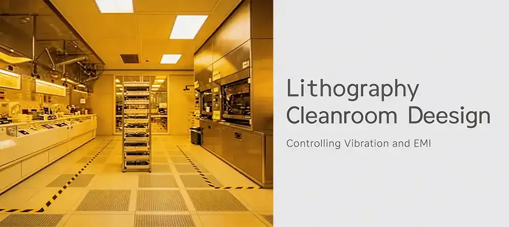
Figure: Integrated design for structural slab, equipment foundation, floating floor, EMI-shielded envelope, FFU ceiling and utility supports.
Why Integrated Control for Vibration and EMI is Essential for Lithography Cleanrooms
Standard solutions for electronic cleanrooms generally fail because they regard vibration, EMI and particle controls as unrelated topics. For lithography, these factors act on eACH other continuously.
For a cleanroom to achieve process stability, it’s inadequate to target ISO standards for particle counts. A semiconductor cleanroom design must consider the interaction of particle and structural dynamics, temperature, humidity, airflow, shielding, and construction quality as a single cohesive system.
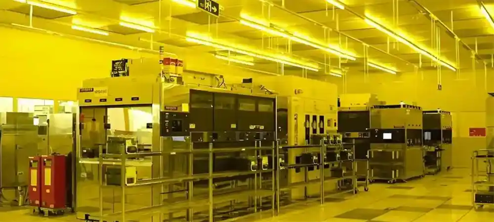
Three risks affecting lithography stability
- Disturbance to the structure and ground: Movement and operation of personnel, equipment, CHT, pumps, HVAC fans, etc. impart energy to the floor.
- Disturbance to the air: The operation of FFUs, flow patterns to and from the cleanroom, air dampers, and pressure fluctuation will disrupt the airflow in the vicinity of the stepper.
- Disruptions in EMI grounding can occur due to the operation of devices, motors, and power distribution RF sources. Disruptions can also occur on interrupted metallic shield interfaces and can create circuits that leak and cause interference with metrology and exposure equipment.
"For lithography, clean air is just the beginning. Stability of all air and utilities is determined by the design of the building, integrated airflow and shielding."
Key Elements for cleanroom design for Lithography Areas in Semiconductors
The design should start with process zoning, not peripheral wall panels. Identify the functional process zones of exposure, coat/develop, metrology, maintenance access, and transfer of materials.
Identify vibration sensitive areas, EMI sensitive areas, high heat areas, and high traffic areas. Depending on the zone, determine the classification of cleanliness, pressure differentials, temperature and humidity, vibration, noise, and EMI.
Design interfaces that require close coordination
- Foundations for equipment and structural slabs
- Wall panels, ceilings and door/window systems of the cleanroom
- FFU/HEPA supply and plenum
- MAU/AHU and pathways of return air
- Process exhaust and chemical fume management
- Grounded cable trays and shield layers
- Supports for equipment, pipe and duct
- Doors for logistics, for access to equipment, and for maintenance
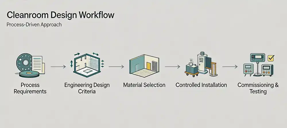
Figure: Process requirements → Engineering design criteria → Selection of materials → Controlling Installation → Commissioning and Testing
Mitigation of Vibrations in Lithography Rooms
Mitigation should remove or isolate sources of vibration, not simply add isolators to the feet of equipment. The starting point for lithography room vibration control is mapping the sources of vibration and the means of transmission.
Examples of sources can include: traffic, building and mechanical systems, AHU/FFU, ducts, pipes, ceiling grids and even the walkways used by personnel.
Isolate products selectively after identifying sources of vibration
- Roads and rail systems
- Structures
- Rotating machinery
- Fan assemblies
- Air ducts
- Ceiling suspension systems
- Tool foundations and access routes
Vibration criterion (VC) curves – choose the grade according to your system
Lithography tools have particular limitations on vibration velocity. The following table summarises the VC grades that are commonly found in the design of semiconductor fabrication. Always check the specifications with your tool vendor.
| VC Level | Velocity Limit (μm/s) | Typical Tool Application |
|---|---|---|
| VC‑C | 12.5 | High‑resolution SEM and optical microscopes |
| VC‑D | 6.25 | 1‑μm‑class steppers and scanners and AFM |
| VC‑E | 3.12 | Sub‑micron / advanced lithography and EUV and critical metrology |
| VC Level | Limit (μm/s) | Tool Application |
|---|---|---|
| VC‑C | 12.5 | SEM, optical microscopes |
| VC‑D | 6.25 | 1‑μm steppers, AFM |
| VC‑E | 3.12 | Advanced lithography, EUV metrology |
Source: Generic VC curves adapted from IEST‑RP‑CC024.1 and tool vendor recommendations.
Vibration control design has four levels.
1. The strategy for structural and equipment foundations
Determine the stiffness and natural frequency of the slab, and if isolated, the sensitive equipment is separated from the rest of the operation. Avoid placing heavy MEP equipment directly above, below, or next to the lithography zones.
2. Isolate all mechanical services from the cleanroom envelope
To break the rigid vibration path from the fans, AHUs, and ductwork, use flexible duct connectors. In practice, flexible connector lengths are typically ≤300 mm and 150–250 mm are the most common. Anti‑sway supports should be installed as close as 1 m from the flexible connector to mitigate secondary vibrations.
⚠️ Pitfall Alert: Unintentional Bridging Between HVAC Supports and Cleanroom Structure
Often, contractors will weld ductwork hangers directly onto cleanroom construction wall panels or ceiling grids. This leads to a rigid vibration route — fan micro-vibrations run straight to the stepper, resulting in VC-D/E validation failures.
Deiiang™ solution: Utilize spring hangers and flexible connectors, fully decoupled from the cleanroom envelope, and independently supported. This solution has been validated on numerous 300mm fab projects.
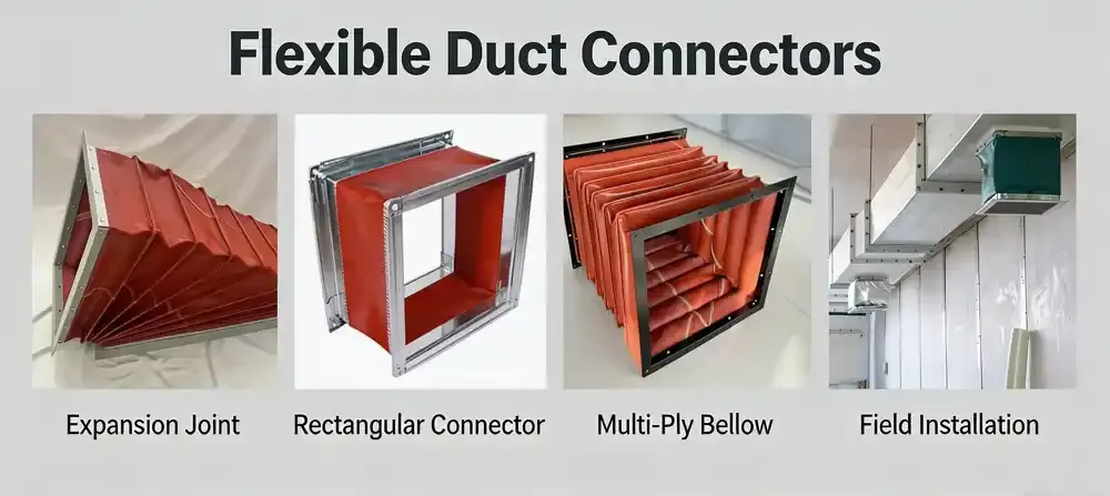
AHU fan outlet → flexible connector → independently supported duct → cleanroom ceiling penetration.
3. Develop systems to minimize vibration
Direct-drive EC fans eliminate the belt-drive vibration and droplet formation while decreasing maintenance. FFU modules typically provide consistent airflow at around 0.45 m/s ±20%. Final air velocities need to be confirmed via CFD and the heat load of the tool. Deiiang™ FFU’s measured airflow uniformity with a CV (coefficient of variation) of ≤ 4.8% — an important factor for airflow stability.
4. Confirm with onsite measurements
Conduct baseline testing for empty room conditions, compare with HVAC systems both on and off, collect data on adjacent equipment start/stop test, and measure during the entire production cycle. After you implement corrections, re-measure and keep a log of all data.
Isolation of vibration should be thought of as a system that is tied to the complete process from the design of the building to the integral operational commissioning of the building.
EMI Shielding Cleanroom Design: From Material Selection to Grounding Continuity
EMI shielding cleanroom design requires a fully integrated shielding solution to create a continuous conductive enclosure. This leads to common failures of gaps between panels, doors, windows, and utility penetrations leading to uncoordinated grounding.
A grounding uncoordinated gap may result in shielding failures of ~20–40 dB with little loss of shielding in these critical frequency bands.
EMI shielding comprises a complete enclosure rather than a metal surface.
- Wall and ceiling panels: Overlaps and proper bonding techniques/disciplines ensure conductive continuity.
- Doors and windows: Conductive gaskets, coupled with shielded glazing and frame continuity, help shield windows.
- Utility penetrations: Shielded conduit, waveguides, and conductive gaskets provide continuity for ducts, cables, and conductive gaskets.
- Ceiling grid and equipment supports: Support structures shall be designed to eliminate unintentional EMI coupling.
- Grounding network: Clearly marked test points define a single-point or mesh ground.
🔬 Expert Callout: Low‑frequency EMI & grounding targets
Within 10 Hz - 1 GHz, lithography shielding systems should support at least 60 dB (80 dB for highly precise polarisation areas). Concurrently, the grounding networks in cleanroom must kept to ≤1.0 Ω of earth resistance. These two will most likely be the cause of EMI related failures when measured against yield.
Reference: IEEE 299 and SEMI F47.
⚠️ Pitfall Alert: EMI leakage between tin seams
Lots of contractors will focus on the metal surface and ignore the oxide layer and the conductive gaskets found between tin seams. This will mean that the attenuation of low-frequency EMI will drop below 60 dB during acceptance testing.
Deiiang™ solution: seamless, multi-point, staggered grounding, conductive gaskets. Flatness verified at ≤0.5 mm/m and ground continuity at<1 Ω across the entire envelope.
Material strategy for cleanroom construction shields in semiconductor fabrication facilities
The panels of the cleanroom need to be flat, structurally stable, and easy to clean. Deiiang's hollow magnesium oxide sandwich panels, with 5 mm top and bottom sheets, 11 offset ribs, and 13 noncollinear splicing points, lend their support to manufacturing continuity and structural shield integrity when bonded, along with ≥1.2 kN/m² bending resistance and ≤0.5 mm/m flatness deviation.
For areas with strict fire control regulations, Class A non-combustible Fire-rat cores are available. Use sealed joints and coved corners to streamline cleaning and maintain integrity of the enclosure.
Shielding performance must be tested after installation.
- Continuity and grounding resistance tests must be performed.
- Scan for leakage around doors, windows, penetrations and air grilles.
- Test shielding effectiveness in critical frequency bands.
- Re-testing must be performed after any modifications or retrofitting.
- Test results, point maps and corrective actions must be documented.
Standard Test Protocols for Field Validation
To ensure credibility and repeatability, Deiiang integrates globally accepted test standards during the commissioning phase. These protocols provide clients with evidence and verifiable data, eliminating the need for guesswork.
- Vibration Testing per ISO 10816 / IEST‑RP‑CC024.1 — velocity and acceleration spectra, 1–100 Hz
- Shielding Effectiveness (SE) per IEEE 299 / EN 50147‑2 — 10 kHz to 18 GHz, measured using transmitting and receiving antennas
- Airflow and Cleanliness per iso 14644‑3 (2019) — particle counting, airflow velocity and airflow uniformity
- Grounding Continuity per IEC 60364‑4‑41 — earth resistance ≤1 Ω, bonding impedance verified
Safe and Reliable HVAC, FFU and Filtration Design for Stable Lithography Environments
There is a direct correlation between air cleanliness, airflow velocity, and uniformity in a semiconductor cleanroom design. Proper FFU design, static pressure, air volume, return path, heat load and airflow, and the organization are the primary design drivers, not the grade of the filter.
Typically, the FFU outlet velocity is in the range of 0.45 m/s ±20%, however the final design velocity and the outlet placement should be determined based on tool specific requirements and validated airflow modeling.
Terminal filtration and ceiling integration.
High-efficiency supply outlets should offer filter replacement, sealing, suspension and maintenance access. A bottom-access design fosters replacement of filters from inside the cleanroom which eliminates the need for personnel to enter the ceiling plenum.
Common setups have a range of components including plenum boxes, insulation, sealing gaskets, pressure clamps, HEPA/ULPA filters, and diffuser plates. Installation must be designed to manage bypass leakage at the ceiling interface.
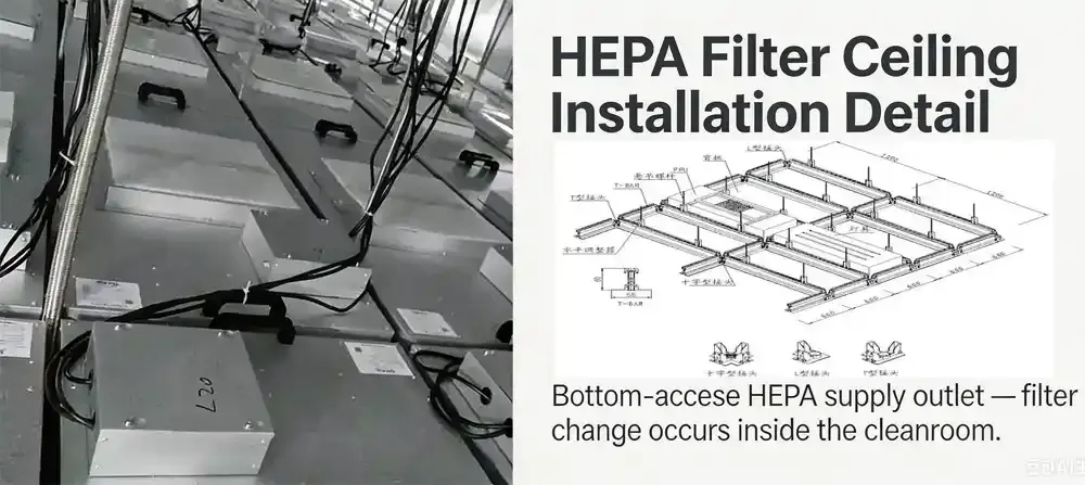
Bottom-access HEPA supply outlet — filter change occurs inside the cleanroom.
Control of Semiconductor MAUs and AMC
For semiconductor manufacturing facilities, make-up air units (MAUs) are designed to handle multiple concerns like particles, temperature and humidity, airflow, air management and controls (AMC), and even changes throughout the seasons. A makeup air unit (MAU) generally has the following order of components between the outside air and cleanroom air: inlet, pre-filter, pre-heat, pre-cool, scrubber, re-cool, re-heat, fan, equalization, chemical filters, a medium filter, and lastly a HEPA filter before air is supplied to the cleanroom.
MAUs for semiconductor manufacturing can be designed to handle air volumes between 40,000 to 180,000 m³/hr at a design static pressure of approximately 800 Pa for each of the manufacturing facilities. The final capacity of the MAUs is determined by the resistance of filter banks, ducting design, and the processes of the facility.
Acoustics and Airflow Control Without Risk of Particulate Contamination
Conventional duct silencers are made from fibrous materials that can shed particles and accumulate dust. Therefore, for lithography clean zones and clean zones of a higher grade, solutions to control noise must be compatible with the cleanliness of that clean zone.
The Compatibility of Cleanroom Requirements with Conventional Duct Silencers
In time, fibrous linings can break down and shed fibers or particles. In critical zones, use metal-based or non-shedding alternatives, and always ensure materials are compatible with cleanroom standards.
Cleanroom Compatibility Stipulations on Duct and Airflow Design
- To make airflow less noisy, you can lower airflow velocity and control route airflow and ducts.
- In clean supply air paths, use materials that do not shed particles.
- Choose dampers, valves, and grilles that will not vibrate or make abnormal noise at the flow rate for which they are designed.
- In general, damper face velocity should not exceed 20 m/s when fully open. Vibration and noise should not be present when dampers are near the closed position.
- Include flexible connections, damper range, and diffuser selection in the system noise budget along with duct velocity and noise level.
Rapid Assessment: Lithography cleanroom grade Estimator
Select your process node and tool type below to receive an estimated cleanliness class along with a VC grade and EMI attenuation target. This tool is based on average industry data, so it is recommended to check with your tool vendor.
Recommended specification:
iso class: —
VC Grade: —
EMI Attenuation: —
(based on typical industry benchmarks; confirm with vendor)
iso class: —
VC Grade: —
EMI Attenuation: —
(based on typical industry benchmarks; confirm with vendor)
Standard vs. Lithography‑grade cleanroom: Key Differences
Vibration
- VC‑B or some building vibration
- ≤50 μm/s (a typical office or lab)
- Does not require a 1 to 100 Hz spectral analysis
EMI Shielding
- Continuous shielding not necessary
- Grounding up to 5 Ω (general building)
- No low‑frequency attenuation spec
Airflow Uniformity
- Velocity is ±20%
- Grade of filter is H13
- No control for turbulence
Construction
- Standard panel joint
- No special EMI gaskets
- Sharing of MEP supports
Vibration
- VC‑D or VC‑E (3.12 – 6.25 μm/s)
- 1‑100 Hz spectra measured
- Isolated foundations & independent supports
EMI Shielding
- ≥60 dB attenuation (10 Hz – 1 GHz)
- Dedicated ground ≤1.0 Ω
- Conductive gaskets, shielded penetrations
Airflow Uniformity
- CV ≤ 5% (velocity uniformity)
- H14 / ULPA or higher
- CFD‑optimized layout
Construction
- Continuous conductive envelope
- Staggered‑rib panels with flatness ≤0.5 mm/m
- Fully decoupled MEP supports
Deiiang Project Case Study: Lithography Cleanroom Upgrade for a Semiconductor Facility
Deiiang™ was responsible for a lithography cleanroom integration within a semiconductor fab expansion project. The project included cleanroom partitioning, an FFU ceiling, EMI shielding, ductwork, and foundations for equipment that are vibration-isolated.
Project overview
- Location: [Country / City]
- Client type: Semiconductor foundry
- Project nature: Lithography area upgrade
- Area: [XX m²]
- Cleanliness class: ISO Class X
- Scope: Panels, ceiling, doors, FFU, duct shielding, installation and testing
The project challenge
Micro-vibration concerns were caused by the mechanical equipment and structural slab modes, adjacent to one another. An access plan was needed to maintain the ceiling, which was dense with FFU, cable trays, ducts, and process tools. Tight constraints on EMI, cleanliness, sealing, and the project schedule required a coordinated effort.
Deiiang's Integrated Solution
- modular cleanroom panels
- Sealed radius corners
- Flexible vibration isolating connections at fan and AHU interfaces
- Independent supports for ducts, cable trays, and heavy utilities
- FFU and HEPA terminal filtration matched to airflow and heat load
- Continuous EMI shielding and grounding along panels, ceiling, doors and penetrations
- Post-construction testing and verification of airtightness, airflow, pressure, vibrations, and EMI
- As-built documentation with tests and guides
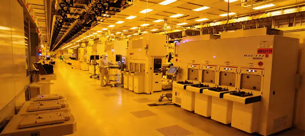
Deiiang lithography cleanroom with FFU ceiling and shielded panels.
Contact Deiiang About Vibration and EMI Control
Create your own custom proposal for a semiconductor cleanroom.
Request a Design ReviewScenario-Based Design - How a Typical Lithography Facility Manager Communicates a Problem
Persona - Daniel, Facilities Manager, Semiconductor Expansion Project
Daniel is the facilities manager for the expansion of a lithography area in a working semiconductor fabrication facility. His team is tasked with constructing new cleanroom partitions, FFUs, and utility routes, along with the necessary shielding, in adjacent areas of the production facility. Typical construction is a concern for Daniel, as he knows that vibration paths are created with ceilings, ducts, and supports for equipment. Daniel wants a vendor that will provide him with the drawings, the materials, the construction details, testing, and documentation for the site.
Deiiang™ serves this purpose for Daniel through early zoning, interface mapping, structural and MEP (Mechanical, Electrical, and Plumbing) coordination and validation on site. The use of standardized details, traceability of materials, and testing fulfill the requirements of a low-risk handover.
Design and Commissioning Checklist for Lithography Cleanrooms
Check off items that are complete by clicking on them. Use the Print button to export your Project Checklist as a PDF.
Before Construction
Confirm process sensitivity criteria (vibration, EMI, cleanliness, temperature).
Map all vibration and EMI sources (internal and external).
Coordinate equipment foundations, HVAC, utilities, and ceiling loads.
Define shielding continuity and grounding interfaces.
Review cleanroom material compatibility and maintenance access.
During Installation
Inspect panel joints, doors, windows, and utility penetrations for continuity.
Prevent rigid vibration bridges between MEP systems and cleanroom structure.
Verify independent supports for ducts, pipes, and heavy utilities.
Keep HEPA/ULPA filters sealed until final installation.
Record all concealed grounding and shielding connections.
Before Handover
Perform airflow, pressure, and leakage testing.
Complete vibration baseline and operating‑condition measurements.
Test EMI shielding and grounding continuity.
Confirm filter installation, scan testing, and replacement access.
Deliver as‑built drawings, test reports, and maintenance instructions.
Frequently Asked Questions
What is the most important design factor in a lithography cleanroom?
Process driven integration. Rather than treating them as separate checklist items, the design of particle control, vibrations, EMI, airflow, and temperature regulation should be done as an integrated system that addresses the requirements of the tools.
How do you reduce vibration in a lithography room?
Identify sources and increase structural stiffness. Use isolated foundations, independent supports, flexible duct connections and measured site verification. A systemic problem cannot be addressed with a single isolator.
Can FFUs create vibration in a semiconductor cleanroom?
Yes. The FFU fans, ceiling grid connections, suspension hardware, and FFU maintenance influence the vibration transmission. Use direct drive EC fans and FFU supports directed in accordance with the structural support design.
What is EMI shielding in a cleanroom?
An EMI shielding takes the form of a continuously conductive enclosure and reduces electromagnetic interference. Panel continuity, bonded seams, shielded doors and windows, and a grounded network are all essential to a complete EMI shielding.
Which cleanroom components require EMI shielding attention?
Welded joints, walls and ceiling panels, doors, observation windows, air grilles, utility penetrations, cable trays, ground network. Any break in the conductive envelope can degrade shielding performance.
What filter classes are used in semiconductor cleanrooms?
HEPA grades H13 (99.97%-99.99% @ 0.3 µm) and H14 (99.995%-99.999% @ 0.3 µm) and ULPA/U grades (U15, U16, U17). Depending on the zone, ULPA/U grades may also be used. Selection depends on ISO class and process sensitivity.
What role do flexible duct connections play in controlling vibrations?
Flexible duct connections decouple the fan or AHU from the ductwork, breaking mechanical continuity between the AHU and ductwork. This decoupling minimizes the transmission of vibrations. However, if these connections are not constructed of appropriate material and supportive structures or if the connections are not sealed, more issues could arise.
How is lithography cleanroom performance verified?
There are no assumptions when verifying lithography cleanroom performance. Testing is done for airflow uniformity, pressure differentials, leakage, the integrity of the filtration, and measuring vibrations and EM fields. Temperature and humidity mapping is also done, along with documented as-built records.
References
- iso 14644-1:2015 — Cleanrooms and associated controlled environments
- iso 14644-4:2022 — Design, construction and start-up
- iso 14644-3:2019 — Test methods
- IEST-RP-CC012.3 — HEPA/ULPA filter testing
- IEST-RP-CC024.1 — Measuring and reporting vibration in cleanrooms
- IEEE 299 — Standard method for measuring shielding effectiveness
- EN 50147-2 — Anechoic chambers / shielding effectiveness
- GB 50243-2016 — Code for acceptance of ventilation and air conditioning construction
- Deiiang™ Technical Library — Cleanroom System Design Guide