+86 13638632902
 Jason@cleanroomequips.com


 MENU
MENU
An iso 5 cleanroom for semiconductor production is not simply a room with more fans and filters. It is a tightly controlled environment where airborne particle concentration, airflow direction, temperature, humidity, electrostatic discharge and pressurization must work together around wafer-level processes. This guide explains how a microelectronics iso 5 cleanroom is specified, designed, built and validated, with practical examples and Deiiang™ project perspectives.
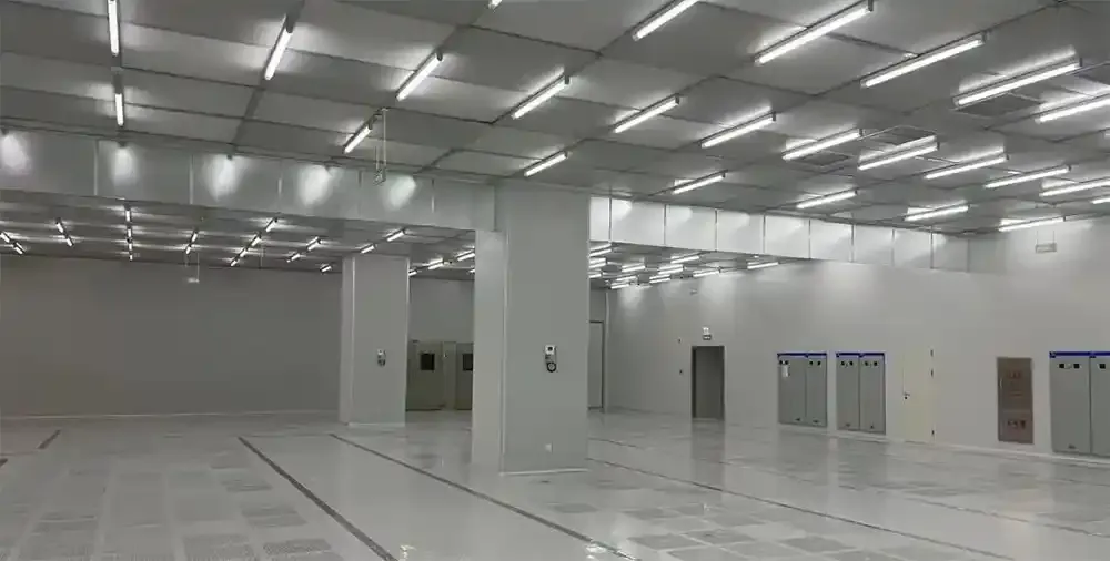
What Is an iso 5 cleanroom?
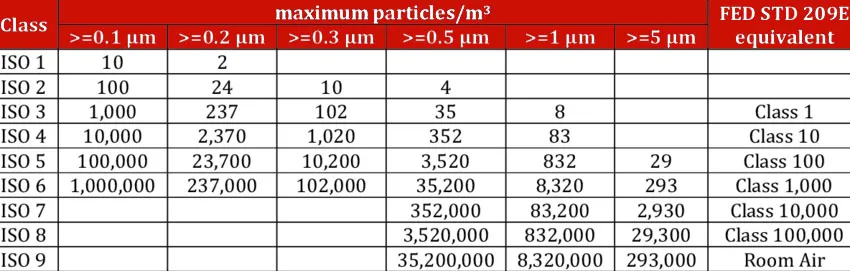
iso 5 is a classification of air cleanliness determined by iso 14644-1. This classification sets concentration limits for airborne contaminants ranging in size from 0.1 μm to 5 μm. The air cleanliness associated with the 0.5 μm particle size permits a maximum of 3,520 particles per cubic meter. It is important to note that a cleanroom is not a one-size-fits-all system, nor a product of an air changes per hour calculation. The design should account for cleanroom area, ceiling height, number of personnel, the heat load of the process, the sources of contaminants, and the airflow pattern.
The 3,520 particles/m³ concentration applies to the 0.5 μm cleaning particle size under ISO classification, which contains specific testing conditions. The project specification should define sampling points, sample volume, the room condition during sampling and define acceptance criteria. In ISO 5, particles of other sizes, 0.3 μm and 0.1 μm, also have concentration limits depending on the cleanroom classification and customer’s validation protocol. Results from testing in the as-built, at-rest, or operational states can be very different from each other, so a single measurement should not be taken as a guarantee of long-term stability.
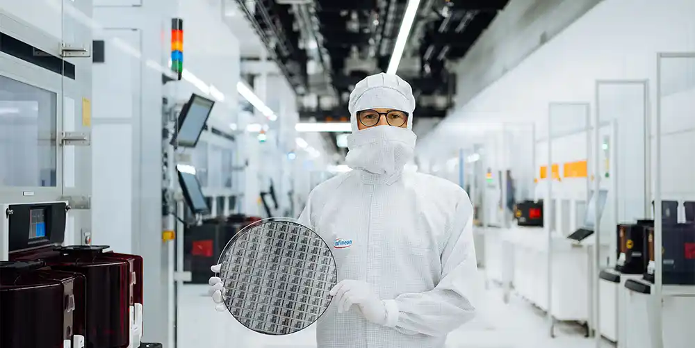
Why ISO 5 Is Important for Semiconductor and Microelectronics Manufacturing
Semiconductor manufacturing requires airborne contamination control at levels far below the visible particulate threshold. In a cleanroom, a single particles occurrence can cause yield loss during any of the processes including lithography, deposition, and packaging. In high-mix production, the cost associated with a cleanroom is justified when considering the cost associated with a cleanroom is justified when the cost associated with rework and scrapped wafers is taken into account. An ISO 5 cleanroom for microelectronics also provides a strong return on investment by reducing these costs.
Typical failure modes associated with particles in microelectronics cleanroom include but are not limited to contamination of the semiconductor wafer, failure of the wafer during electrical operation, lithography masks having defects, and loss of yield during the testing and packaging of the semiconductor.
Decision Guide: Is Full-Room ISO 5 Right for Your Process?
| Process / Area | Common Cleanroom Strategy | Needs Full-Room ISO 5? |
|---|---|---|
| Wafer critical processing | ISO 5 or local ISO 5 | Depends on process and equipment |
| Lithography key zones | ISO 5 / minienvironment | Usually prioritize critical zones |
| Wafer inspection | ISO 5 or local high-clean zone | Depends on inspection accuracy |
| General electronics assembly | ISO 7/8 or local clean zone | Usually not required |
| Material buffer and gowning | Lower clean class with pressure cascade | No |
| Wafer critical processing ISO 5 or local ISO 5 · Depends on process and equipment |
| Lithography key zones ISO 5 / minienvironment · Usually prioritize critical zones |
| Wafer inspection ISO 5 or local high-clean zone · Depends on inspection accuracy |
| General electronics assembly ISO 7/8 or local clean zone · Usually not required |
| Material buffer and gowning Lower clean class with pressure cascade · No |
Do not select full-room ISO 5 just because it seems "better" as the higher number. The decision must consider the contamination risk assessment, equipment suppliers, cost of ownership, and the expected impact on yield. Deiiang™ suggests using a risk-based zoning approach, which means that ISO 5 should only be reserved for highly sensitive areas, while support zones should be at a lower class. The “ballroom cleanroom plus local ISO 5 minienvironments” option provides the best compromise for contamination control against operating cost.
iso 5 cleanroom requirements for Wafer Processing
An ISO 5 cleanroom dedicated to wafer processing should also be designed with more than just the particle count in mind. The key areas should be designed as outlined in the table below. The parameters must be verified with the equipment supplier, because lithography tools, coaters, developers, wet benches, and inspection tools may impose stricter local requirements than an ISO 5 at the room level.
| Design item | Design focus |
|---|---|
| Air cleanliness | Particle control per ISO 14644-1 and customer acceptance criteria |
| Airflow pattern | Unidirectional flow or validated low-turbulence air distribution |
| Filtration | HEPA or ULPA filters selected by pressure drop, airflow and leak-test requirements |
| Temperature & humidity | Determined by wafer process, resist sensitivity, materials and metrology equipment |
| Differential pressure | Prevent cross-contamination from lower-cleanliness zones; balance with process exhaust |
| Materials | Low particle shedding, cleanable, chemical-resistant, ESD-safe surfaces |
| Validation tests | Particle, airflow, pressure, filter integrity, temperature and humidity checks |
| Air cleanliness Particle control per ISO 14644-1 and customer acceptance criteria |
| Airflow pattern Unidirectional flow or validated low-turbulence air distribution |
| Filtration HEPA or ULPA filters selected by pressure drop, airflow and leak-test requirements |
| Temperature & humidity Determined by wafer process, resist sensitivity, materials and metrology equipment |
| Differential pressure Prevent cross-contamination from lower-cleanliness zones; balance with process exhaust |
| Materials Low particle shedding, cleanable, chemical-resistant, ESD-safe surfaces |
| Validation tests Particle, airflow, pressure, filter integrity, temperature and humidity checks |
Particle control
ISO 5 is an air cleanliness class, not a product cleanliness class. Particle testing should specify the target particle size. Static, at-rest and operational states can produce different results. A microelectronics iso 5 cleanroom should not rely on a single “coverage rate” number. Particle counts must be confirmed against the contract, design specification and third-party test report.
Airflow pattern
Cleanrooms designed for semiconductor applications should use vertical unidirectional flow, horizontal unidirectional flow, or non-unidirectional flow. Almost all cleanrooms designed for semiconductors use ffu with side return air and a raised floor. The use of airflow management in cleanrooms should be limited. It has been shown that high air volume in cleanrooms often leads to increased turbulence, increased energy usage, increased re-entrainment of particles, increased noise, and discomfort among operators. FFU coverage and return air paths should be designed employing either CFD or empirical calculations.
For instance, suppose a 60 m² lithography bay is designed as a full-ceiling unidirectional flow, with a nominal supply velocity of 0.35 m/s. We would expect the supply airflow to be 60 x 0.35 x 3600 = 75,600 m³/h. This is NOT a general requirement for ISO 5 and must not be used as a basis for quotations. A project-specific airflow study is mandatory. The number of FFUs is then calculated by taking this airflow and dividing it by the actual FFU working airflow at the corresponding filter pressure drop.
HEPA and ULPA filtration
Selection of a HEPA or an ULPA filter will depend on the level of control required for particles, sensitivity to changes in pressure drop or airflow, energy, and the accessibility of filter replacement. Integrity testing of the filters is routinely done during qualification of an ISO 5 cleanroom and is to be documented in the approved validation protocol and the project specifications. Avoid stating on any filters that it “removes 100% of all particles.” Rather the statement that HEPA/ULPA filters are able to provide a minimum collection efficiency at the most penetrating particle size, is confirmed through a factory test and an on-site scan test, is statement that is correct.
Temperature, humidity and static control
Peak performance during wafer processing and microelectronic assembly relies on the stability of temperature and relative humidity, protection against ESD, low outgassing materials, and a variety of contaminations (especially chemicals and vapors) and the removal of contaminating processes. For lithography, inspection, and precision assembly, the requirements of the Process Equipment Supplier should supersede the general Room-Level values. In regions of high humidity, Deiiang™ calculates latent loads and control of dew point and moisture based on project location instead of applying a generic capacity factor.
ISO 5 cleanroom design for Semiconductor Manufacturing
Designing an iso 5 cleanroom for semiconductor manufacturing involves multiple disciplines. The process starts with contamination source investigation and ends with validation documentation. A typical Deiiang™ design workflow includes:
Handover documentation and maintenance training
Contamination source and process surveys
Planning of clean zones, personnel, and material flow
Setting of cleanliness and pressure cascade
Simulation of airflow and calculation of HVAC load
Selection of FFU, filters, and return air systems
Design of enclosures, doors, windows, and ceilings
Integration of equipment, piping, and services
Construction, commissioning, and on-site testing
Validation related to ISO 14644
Submission documents and maintenance training
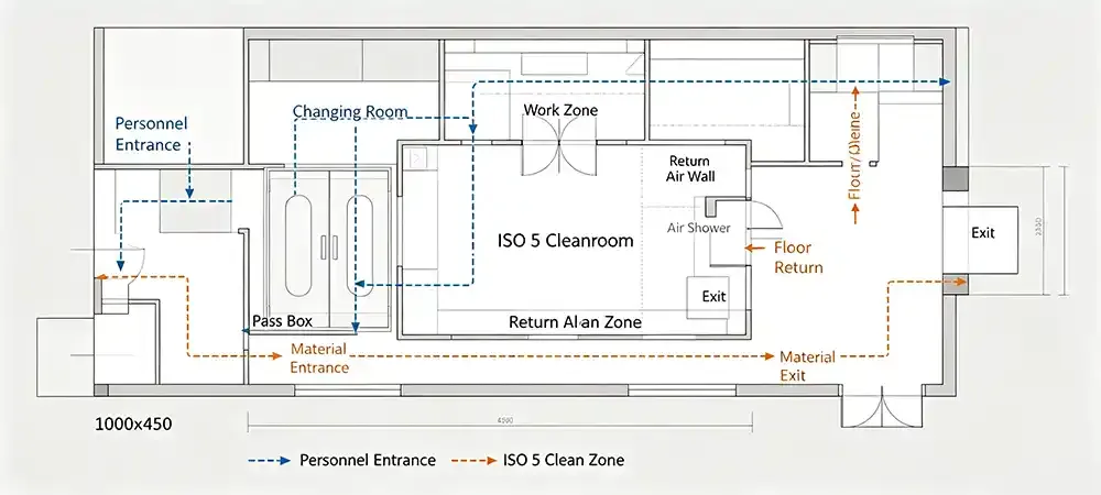
A typical strategy for separation of personnel and material flows is shown in Figure 2. Operators enter through a gowning room, an air shower, and a transfer buffer. Wafers or microelectronic components enter through pass-through chambers. This reduces particle loads at the boundaries of the cleanroom.
Figure 3 shows how FFUs interact with HEPA/ULPA filters, the return air shafts, and the raised access floor. Figure 4 displays the project flow from design verification to conducting performance tests. For a microelectronics ISO 5 cleanroom project, these examples show the necessary details.
How Deiiang Builds ISO 5 Cleanrooms
Deiiang™ configures ISO 5 cleanroom systems according to the required cleanroom size, ceiling layout, process load and customer specification. Final airflow and filter selection are confirmed through project-specific calculations and validation testing. Product design lead: Jason.peng.
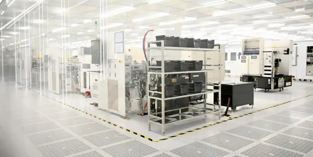
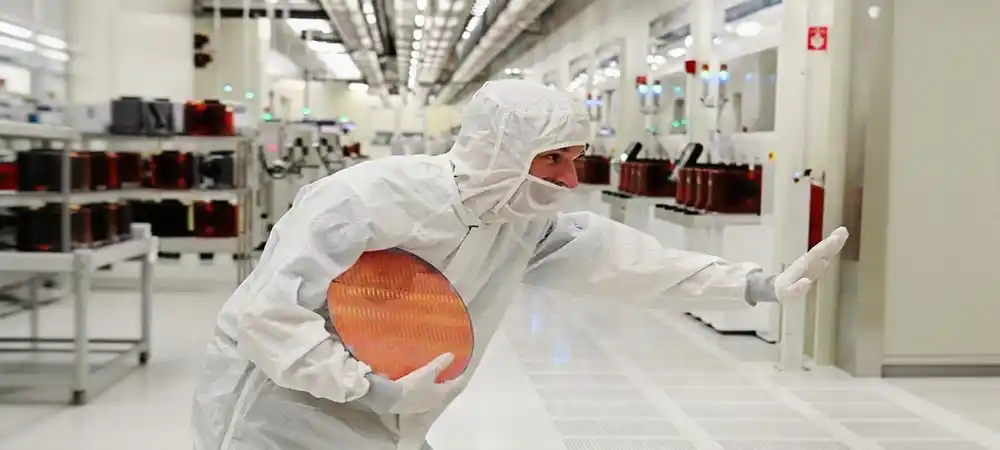
Typical product data modules that can be configured for an iso 5 cleanroom for wafer processing include:
- FFU model, dimensions and rated airflow
- Motor type and speed control method
- Filter grade and initial pressure drop
- Cleanroom wall panel thickness and core material
- Door size, observation window and sealing structure
- Ceiling load capacity and hanging support
- Floor material and surface resistance
- Temperature and humidity control range
- Control system and monitoring point quantity
- Noise level and energy data
- Factory prefabrication ratio
- Project warranty period
Deiiang ™ avoids using generalized percentages such as (35%–50% FFU coverage) or (20% energy savings) in the absence of a dedicated design file. The number of coverage and room dimensions, tool heat load, exhaust volume, and target unidirectional velocity determines the percentage of coverage, and the preliminary airflow should always be supported with CFD or empirical research and validated with onsite measurements.
ISO 5 cleanroom testing and Validation
The validation of an iso 5 clean room for semiconductor applications must be considered prior to construction, and not post construction. Deiiang ™ has a structured sequence that correlates with ISO 14644 and the customer's specified URS.
- Design review and installation check
- FFU and filter installation verification
- Airflow volume and velocity testing
- Differential pressure cascade confirmation
- Airflow direction and recovery test
- Temperature and humidity uniformity test
- Particle count test under defined room state
- HEPA/ULPA filter integrity scan test
- Documentation delivery and deviation closure
The test scope and frequency vary by project. Always refer to the contract, customer URS, applicable standards and local codes. Deiiang™ provides full documentation for each validation step to support client audits and future maintenance.
Cost and Delivery Considerations
Total project cost for a microelectronics iso 5 cleanroom is driven by cleanroom area, room height, ISO zoning, process utilities, HVAC load, validation scope, local construction conditions and delivery requirements—not by cleanroom area alone. Key factors include:
- Cleanroom area and ceiling height
- Percentage of ISO 5 zones
- HVAC and dehumidification load
- FFU quantity and speed control method
- HEPA/ULPA configuration
- Raised floor and return air shaft design
- Process exhaust and utility connections
- ESD, chemical resistance and fire protection requirements
- Local labor, material and regulatory conditions
- New construction or existing building retrofit
Delivery time depends on factory prefabrication ratio, site readiness, design approval and validation schedule. A modular cleanroom approach often shortens on-site installation compared with traditional stick-built methods, but this benefit must be confirmed per project.
What Is Included in a Turnkey ISO 5 Cleanroom?
Clear delivery boundaries are essential for accurate budgeting and accountability. Deiiang™ typically provides the following scope for an ISO 5 cleanroom project:
- Conceptual and detailed cleanroom design
- Modular wall, ceiling and door system
- FFU and HEPA/ULPA filter supply
- HVAC equipment and ducting
- Raised floor or floor finishing
- Electrical, lighting and control system
- BMS/EMS integration
- Process exhaust connections
- Installation, commissioning and validation
- Training and handover documentation
Items typically supplied by the client or other contractors may include process equipment, facility utilities, civil works, fire suppression, and structural supports. Deiiang™ clarifies these boundaries during the design review stage to avoid scope gaps.
Representative ISO 5 Cleanroom Design Example
The following example outlines an engineering reference scenario. This is not a reference example of a specific customer project. Actual dimensions, particle results, and validation criteria will vary in accordance with the specific processes, equipment layouts, and local regulations. All numbers in the example are for illustration purposes only and must be supported by design and testing for the specific project.
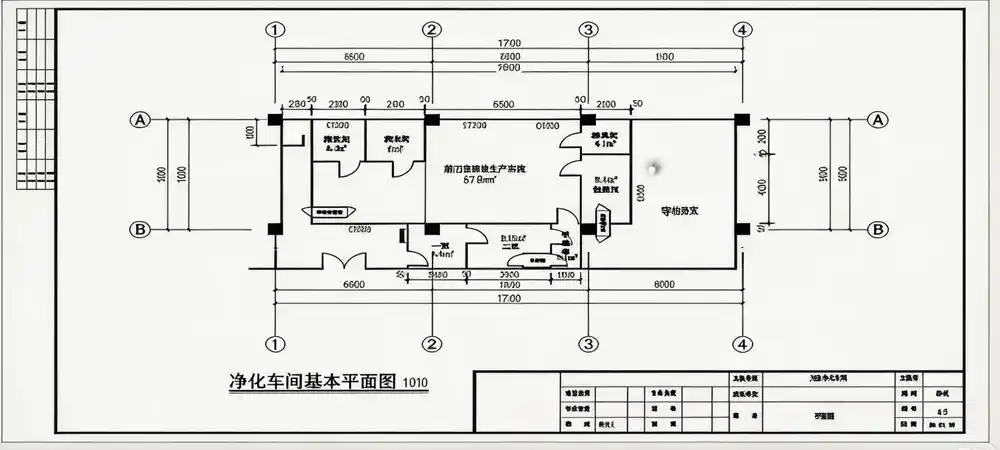
Reference design overview
This example scenario depicts a clean room design constraint of 180 m², including ISO 5 clean room zones for critical process steps, and ISO 6 support zones for material handling. It is likely that Deiiang ™ would be responsible for clean room design integration for its modular enclosures, HVAC integration, and support installation, as well as the clean room performance testing, in the project scope mentioned.
Typical challenges
- Existing building renovation with limited ceiling height
- High equipment heat load from wafer inspection tools
- Personnel and material flow crossover risk
- Connection to existing HVAC plant
- Tight construction schedule and local seismic requirements
Deiiang™ reference solution
Modular cleanroom design allows for the rapid installation of cleanroom systems. FFU and return airpaths are designed for the equipment layout. Different gowning, pass-through, and buffer zones are included. unidirectional airflow is reinforced in tool areas. A system is used to monitor pressure, temperature, and humidity, and to provide alarms during the commissioning and operation of the system. Pre-commissioning tests include filter scans, airflow velocity measurements, particle counts, and pressure cascades.
Reference design data
| Parameter | Illustrative value |
|---|---|
| Cleanroom area | 180 m² (example) |
| ISO class | ISO 5 in critical zones (example) |
| 0.5 μm particle result | Below 3,520 particles/m³ in at-rest state (example) |
| Airflow uniformity | Established in design spec and verified by site testing |
| Differential pressure | Maintained positive cascade per design |
| Filter integrity | Passed HEPA/ULPA scan test (example) |
| Temperature stability | Confirmed per process equipment specification |
| Construction period | Shortened by modular prefabrication (project-dependent) |
| Cleanroom area 180 m² (example) |
| ISO class ISO 5 in critical zones (example) |
| 0.5 μm particle result Below 3,520 particles/m³ in at-rest state (example) |
| Airflow uniformity Established in design spec and verified by site testing |
| Differential pressure Maintained positive cascade per design |
| Filter integrity Passed HEPA/ULPA scan test (example) |
| Temperature stability Confirmed per process equipment specification |
| Construction period Shortened by modular prefabrication (project-dependent) |
Site photos, videos and third-party test reports are available on request for actual Deiiang™ projects. The data above should not be used as a guarantee for any specific project outcome.
About Deiiang cleanroom engineering Experience
Deiiang™ has offered modular cleanroom systems for semiconductor, microelectronics, and precision manufacturing projects in many areas. The engineering team has close cooperation with process equipment suppliers, HVAC contractors, and the validation team to tailor the cleanroom engineering to the performance and production specifications.
Our experience includes cleanrooms of ISO classes 5 to 8, FFU-based unidirectional flow systems, cleanrooms with integrated raised floors and return air, and cleanroom monitoring and validation. We provide cleanrooms operation and maintenance technical documentation and training, as well as after-sales support.
Frequently Asked Questions
ISO 5 is approximately equivalent to US federal standard 209e Class 100 at 0.5 μm. However, the exact comparison depends on the particle size and test method used.
There is no single fixed air change rate. A unidirectional flow ISO 5 cleanroom is often designed around average air velocity, such as 0.30–0.45 m/s, rather than air changes per hour. Non-unidirectional ISO 5 zones may use higher air change rates, but this must be calculated.
No. ISO 5 should be used only for high-sensitivity areas such as wafer critical processing, lithography, inspection, and precision assembly. Lower-risk areas can operate at ISO 6, ISO 7 or iso 8. A combination of ballroom cleanroom plus local ISO 5 minienvironments often provides the best balance between contamination control and operating cost.
Preliminary ISO 5 Unidirectional Flow Estimator
Enter values to estimate theoretical supply airflow and FFU quantity for a full-ceiling unidirectional flow design. This is for preliminary planning only and is not a final cleanroom design.
Engineer’s Field Notes: Common Pitfalls to Avoid
Based on Deiiang™ field experience, the following issues frequently cause schedule delays, cost overruns or validation failures in semiconductor cleanroom projects.
Quoting by area alone. A 100 m² lithography zone and a 100 m² packaging zone can have completely different HVAC, FFU, exhaust and validation costs.
Ignoring process exhaust balance. Equipment exhaust affects pressure cascade, make-up air and airflow direction. Confirm the equipment list early.
Construction before validation criteria are defined. If test states, sampling points and acceptance limits are unclear, rework and re-testing may be required.
Selecting filters by class only. Efficiency, pressure drop, airflow, energy consumption and replacement space must be evaluated together.
Neglecting personnel and material flow discipline. Reaching ISO 5 does not guarantee stability if operators bypass gowning or pass-through protocols.
References
- iso 14644-1:2015 — Cleanrooms and associated controlled environments — Part 1: Classification of air cleanliness by particle concentration. https://www.iso.org/standard/53394.html
- ISO 14644-2:2015 — Monitoring to provide evidence of cleanroom performance related to air cleanliness by particle concentration. https://www.iso.org/standard/53395.html
- IEST-RP-CC034.4 — HEPA and ULPA Filter Leak Tests. https://www.iest.org/Standards-RPs/Recommended-Practices
- SEMI Standards — Semiconductor manufacturing environment, equipment and safety. https://www.semi.org/en/standards
The examples and preliminary calculations on this page are for technical orientation only. Final cleanroom classification, airflow, filter selection, HVAC capacity, pressure cascade and validation criteria must be confirmed by project-specific design calculations, equipment requirements, local codes and approved test protocols.
Deiiang™ · Product design lead: Jason.peng · For project-specific ISO 5 cleanroom design, verify all parameters with the latest customer specification, local codes and on-site validation data.